REDEX KRPX+ Manual

Rack and Pinion Drives
KRPX+
Mounting, Setup and Maintenance
Instructions
Document: RX182/010
Version: 01/2017

Language Summary:
I. English
II. French / Français
III. German / Deutch
IV. Spanish / Español
V. Italian / Italiano
VI. Chinese / 简体中文

KRPX+ User manual
Ref.: RX182/010
Version 01/2017 - English
This document must not be reproduced nor information therein disclosed without our authorization
Page 1 / 24
Summary: English version
1INTRODUCTION 2
1.1 WARNINGS 2
1.2 GEARBOX IDENTIFICATION 2
1.3 LONG TERM STORAGE 2
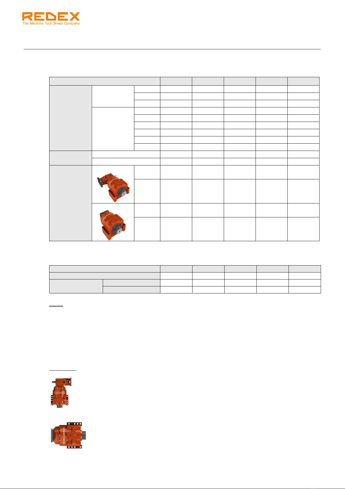
2TECHNICAL DATA 3
2.1 GEARBOX 3
2.2 OUTPUT PINION 3
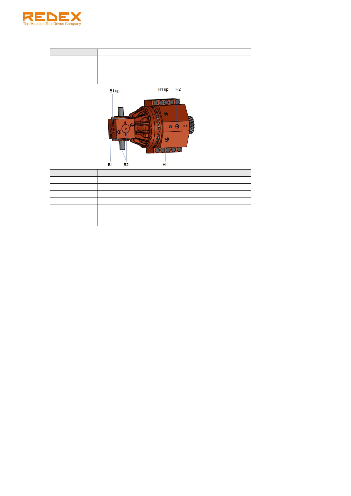
2.3 MOUNTING POSITION NOMENCLATURE 3
3LUBRICATION 4
3.1 RECOMMENDED LUBRICANTS 4
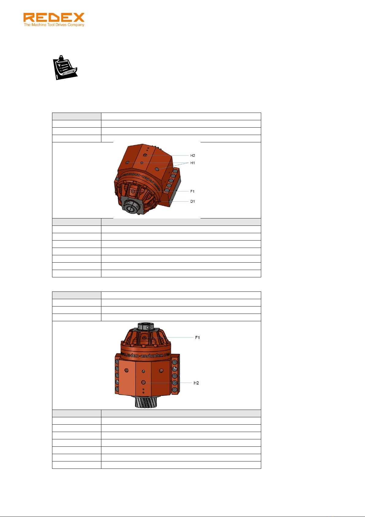
3.2 OIL FILLING:RIGHT-ANGLE CONFIGURATION (KRPX+R) 4
3.3 OIL FILLING:MOTOR IN-LINE CONFIGURATION (KRPX+M) 8
3.4 OIL DRAINING 10
4INSTALLATION ON THE MACHINE 11
4.1 RACK MOUNTING TOLERANCE 11
4.2 KRPX+ PERPENDICULARITY TOLERANCES 12
4.2.1 SET UP DATA 12
4.2.2 SET UP METHOD 12
4.3 KRPX+ HEIGHT SETTING 13
4.3.1 SET UP DATA 13
4.3.2 SET UP METHOD 15
4.4 PROPER TOOTH MESHING VALIDATION 16
4.5 TOOTH CONTACT PATTERN CHECK 17
4.6 KRPX+ FINAL FIXING 17
4.7 INSTALLATION IN CASE OF ROTARY DRIVE 18
5MOTOR INSTALLATION 19
5.1 MF-TYPE MOTOR FLANGE MOUNTING (FOR RIGHT ANGLE CONFIGURATIONS KRPX+R AND CYLINDRICAL SHAFTS) 19
5.2 MF-TYPE MOTOR FLANGE MOUNTING (FOR RIGHT ANGLE CONFIGURATIONS KRPX+R AND TAPER SHAFTS) 20
5.3 IF-TYPE MOTOR FLANGE MOUNTING (FOR IN-LINE CONFIGURATIONS KRPX+M) 21
6RACK & PINION LUBRICATION: OPTIONAL LUBE PINION (PGRP) AND LUBE PINION SUPPORT
(SFRPX) 24
6.1 DESCRIPTION OF THE PGRP &SFRP OPTIONS 24
6.2 RECOMMENDED LUBRICANTS 24
6.3OIL FLOW RATES 24

KRPX+ User manual
Ref.: RX182/010
Version 01/2017 - English
This document must not be reproduced nor information therein disclosed without our authorization
Page 2 / 24
1 INTRODUCTION
The KRPX+ planetary gearbox will give you complete satisfaction if all of the following mounting,
operating & maintenance instructions are respected.
1.1 Warnings
WARNING! HANDLING OPERATIONS.
The KRPX+ unit can be handled by the main housing or, with lifting rings, by the pinion
tapped hole.
WARNING! LUBRICATION REQUIREMENTS.
The rack and the output gears must be lubricated before running the KRPX+. The KRPX+
is delivered WITHOUT OIL: refer to lubrication chapter in this manual to respect all
lubrication requirements.
Any damage due to incorrect lubrication will void the warranty.
1.2 Gearbox identification
Each unit can be identified through its identification plate and the serial number indicated on it. The serial
number must be given for any correspondence on a particular unit.
1.3 Long term storage
Each gearbox is delivered wrapped and greased for 1 month anti-corrosion protection. Gearboxes which
are not installed shortly after receipt should be stored in a dry atmosphere with temperature between 0°C
& 40°C. The unit must be filled completely with oil for storage.
Serial number
Drawing code
Designation
Shipment date
Reduction ratio
Backlash (if
needed)
861607
RX128460-12
KRPX4+R.31.3.H
NOV. 2016
31

KRPX+ User manual
Ref.: RX182/010
Version 01/2017 - English
This document must not be reproduced nor information therein disclosed without our authorization
Page 3 / 24
2 TECHNICAL DATA
2.1 Gearbox
KRPX1+
KRPX2+
KRPX3+
KRPX4+
KRPX5+
Maximum
acceleration
output
torque (Nm)
1 st.
i=5
648
1750
-
-
-
i=7
665
1750
i=10
473
1400
-
-
-
2 st.
i=17
683
1838
3238
6125
-
i=21
534
1400
2625
6125
7520
i=31
753
2100
3850
6300
10050
i=46
473
1400
2468
4480
8800
i=61
656
2013
2695
4970
8800
i=91
473
1400
2695
4970
8800
Max. input
Speed (rpm)
1 st. i=5, 7, 10
5000
5000
4000
-
-
2 st. i=21 to 91
6000
6000
6000
5000
4000
Approx.
Weight (kg)
KRPX+R
1 st.
30
68
-
-
-
2 st.
32
71
143
233
350
KRPX+M
1 st.
28
61
-
-
-
2 st.
30
64
130
202
310
2.2 Output pinion
KRPX1+
KRPX2+
KRPX3+
KRPX4+
KRPX5+
Module
3
4
5
6
8
Theoretical pitch
diameter (mm)
Helical: 19°31'42''
57.30
76.39
95.49
114.59
127.32
Straight
57
76
95
114
128
Note:
Data are subjected to change without prior notices.
2.3 Mounting position nomenclature
Output flange position / motor flange position (if different) with:
- B5 horizontal
- V1 vertical down
- V3 vertical up
Examples:
V1/B5: output flange vertical down / motor flange horizontal
B5: output flange & motor flange horizontal

KRPX+ User manual
Ref.: RX182/010
Version 01/2017 - English
This document must not be reproduced nor information therein disclosed without our authorization
Page 4 / 24
3 LUBRICATION
3.1 Recommended lubricants
WARNING!
The KRPX+ is delivered WITHOUT oil. Fill it with oil before using.
Any damage due to incorrect lubrication will void the warranty.
WARNING!
The rack and the output gears must be lubricated before running the KRPX+.
We recommend using a synthetic PAO based oil with viscosity 150Cst at 40°C to lubricate the KRPX+
such as one of the followings (or an equivalent); for alternates, please consult us.
Trade mark
Oil reference
KLUBER
KLUBERSYNTH EG 4-150
MOBIL
MOBILGEAR SHC XMP 150 or
MOBIL SHC629 (warning: life time 7500 hours)
TOTAL
CARTER SH150
SHELL
OMALA HD150
LUBCON
TURMOSYNTHOIL 150
3.2 Oil filling: right-angle configuration (KRPX+R)
KRPX+ are delivered with sight glasses and breathers in a separate plastic bag. They must be installed in
the correct position described in the following procedure and sketches.
Place the sight glass in the correct position.1.
Remove the input plug of the KRPX+R.2.
Fill the KRPX+ slowly until the oil level reaches the middle of the sight glass. Note that the level on3. the sight glass may take some time to stabilize.
Re-install the oil input plugs.4.
Install the breather at the place of the red plug.5.
Run the unit until it reaches operating temperature. Stop the unit, check and adjust the level.6.
WARNING!
An O-ring seal insures the leak tightness of the oil plugs. Carefully tighten the plugs in
order to avoid damaging the seal.

KRPX+ User manual
Ref.: RX182/010
Version 01/2017 - English
This document must not be reproduced nor information therein disclosed without our authorization
Page 5 / 24
Position:
B5/B5
Oil input
H1, H2, B1, B1’
Oil draining
D1
Breather
B1
Sight glass
B2
Size
Approximated oil quantity (L)
KRPX1+R 1st.
0,7
KRPX1+R 2st.
0,4
KRPX2+R 1st.
1,6
KRPX2+R 2st.
0,9
KRPX3+R
1,6
KRPX4+R
2,7
KRPX5+R
5,6
Position:
B5/V1 or B5/V3
Oil input
H1, H2, B1
Oil draining
D1
Breather
B1 with elbow
Sight glass
B2
Size
Approximated oil quantity (L)
KRPX1+R 1st.
0,7
KRPX1+R 2st.
0,4
KRPX2+R 1st.
1,6
KRPX2+R 2st.
0,9
KRPX3+R
1,6
KRPX4+R
2,7
KRPX5+R
5,6

KRPX+ User manual
Ref.: RX182/010
Version 01/2017 - English
This document must not be reproduced nor information therein disclosed without our authorization
Page 6 / 24
Position:
V1/B5
Oil input
B1, B2 up
Oil draining
H2
Breather
B1 or B1’ with elbow
Sight glass
B2
Size
Approximated oil quantity (L)
KRPX1+R 1st.
Consult us
KRPX1+R 2st.
0,7
KRPX2+R 1st.
Consult us
KRPX2+R 2st.
1,5
KRPX3+R
4,0
KRPX4+R
5,0
KRPX5+R
9,0
Einbaulage:
V3/B5
Oil input
H2
Oil draining
B1
Breather
N/A
Sight glass
H2 (no sight glass)
Size
Advised oil flow rate (L/min)
KRPX1+R 1st.
Consult us
KRPX1+R 2st.
0,5
KRPX2+R 1st.
Consult us
KRPX2+R 2st.
1,0
KRPX3+R
2,0
KRPX4+R
2,5
KRPX5+R
3,0
WARNING!
This mounting position may require a special procedure for oil filling. Please consult us.

KRPX+ User manual
Ref.: RX182/010
Version 01/2017 - English
This document must not be reproduced nor information therein disclosed without our authorization
Page 7 / 24
Position:
B5/B5
Oil input
B1 up, H1 up
Oil draining
B1, H1
Breather
B1 up with elbow
Sight glass
B2
Size
Approximated oil quantity (L)
KRPX1+R 1st.
0,7
KRPX1+R 2st.
0,4
KRPX2+R 1st.
1,6
KRPX2+R 2st.
0,9
KRPX3+R
1,6
KRPX4+R
2,7
KRPX5+R
5,6

KRPX+ User manual
Ref.: RX182/010
Version 01/2017 - English
This document must not be reproduced nor information therein disclosed without our authorization
Page 8 / 24
3.3 Oil filling: motor in-line configuration (KRPX+M)
Remove the dedicated oil input and oil level plugs.1.
Fill the KRPX+ with oil until the oil comes out of the level hole.2.
Replace the plugs.3.
Position:
B5
Oil input
H1, H2
Oil draining
D1
Oil level
F1
Size
Approximated oil quantity (L)
KRPX1+M 1st.
0,2
KRPX1+M 2st.
0,2
KRPX2+M 1st.
0,6
KRPX2+M 2st.
0,6
KRPX3+M
1,0
KRPX4+M
1,6
KRPX5+M
3,5
Position:
V1
Oil input
F1
Oil draining
H2
Oil level
F1
Size
Approximated oil quantity (L)
KRPX1+M 1st.
0,4
KRPX1+M 2st.
0,4
KRPX2+M 1st.
1,0
KRPX2+M 2st.
1,3
KRPX3+M
1,80
KRPX4+M
3,4
KRPX5+M
6,2

KRPX+ User manual
Ref.: RX182/010
Version 01/2017 - English
This document must not be reproduced nor information therein disclosed without our authorization
Page 9 / 24
Position:
V3
Oil input
H2
Oil draining
F1
Oil level
H2
Size
Approximated oil quantity (L)
KRPX1+M 1st.
KRPX1+M 2st.
KRPX2+M 1st.
KRPX2+M 2st.
KRPX3+M
KRPX4+M
KRPX5+M
WARNING!
This mounting position may require a special procedure for oil filling. Please consult us.
Position:
B6 –B7
Oil input
F1 up, H1 up
Oil draining
F1 down, H1
Oil level
F1, H2
Size
Approximated oil quantity (L)
KRPX1+M 1st.
0,2
KRPX1+M 2st.
0,2
KRPX2+M 1st.
0,6
KRPX2+M 2st.
0,6
KRPX3+M
1,0
KRPX4+M
1,6
KRPX5+M
3,5

KRPX+ User manual
Ref.: RX182/010
Version 01/2017 - English
This document must not be reproduced nor information therein disclosed without our authorization
Page 10 / 24
3.4 Oil Draining
We advise to change oil after 10000 hours running.
In order to remove all residual particles in oil, do not hesitate to:
- Run the unit before draining in order to reduce the viscosity of the old lubricant
- “Wash” the unit with fresh oil before refilling.
Unscrew the oil input plugs of the KRPX+ to allow air entering the gearbox.1.
Unscrew the oil output plugs and wait until no more oil flows out from the unit.2.
NOTE:
Drained oil is a special industrial waste and should be handled according to current laws.

KRPX+ User manual
Ref.: RX182/010
Version 01/2017 - English
This document must not be reproduced nor information therein disclosed without our authorization
Page 11 / 24
4 INSTALLATION ON THE MACHINE
WARNING! HANDLING OPERATIONS.
The KRPX+ unit can be handled by the main housing, the bevel box shafts, or, with lifting
rings by the pinion tapped hole.
4.1 Rack mounting tolerance
Parallelism between the rack reference surface and the linear guide
The KRPX+ requires that the rack has been installed on the machine following the rack manufacturer
mounting procedure and respects the tolerances shown below:
We advise to measure the parallelism error values on 3 points for each segment of rack, as shown on the
drawing below. This rack topography will be used for proper tooth meshing validation and preload
setting (see next chapters).
In order to control the pitch error, we also recommend doing 3 measurements at each connection of 2
rack segments, as shown on the sketch below.
The variation between the 3 comparators at each connection must not exceed:
- 0.015 mm for a rack module 3,
- 0.020mm for a rack module > 3.
SIZE
Maximum parallelism errors between rack &
linear guide
Pin
diameter to
use
For 1 rack
section
For
complete
axis length
KRPX1+
6 mm
0.02 mm / m
0.05 mm
KRPX2+
8 mm
0.02 mm / m
0.05 mm
KRPX3+
10 mm
0.02 mm / m
0.05 mm
KRPX4+
12 mm
0.04 mm / m
0.07 mm
KRPX5+
16 mm
0.06 mm / m
0.08 mm

KRPX+ User manual
Ref.: RX182/010
Version 01/2017 - English
This document must not be reproduced nor information therein disclosed without our authorization
Page 12 / 24
4.2 KRPX+ perpendicularity tolerances
4.2.1 Set up data
Adjusting the perpendicularity of the pinion axis to the rack by controlling the parallelism between the front
face of the KRPX+ and the rack
SIZE
Maximum parallelism errors
between KRPX+ front face and rack
LZ(1) - LZ(2)
KRPX1+
0.020 mm
KRPX2+
0.020 mm
KRPX3+
0.025 mm
KRPX4+
0.025 mm
KRPX5+
0.030 mm
4.2.2 Set up method
Using key way
Without using key way
Use the key way on gearbox bottom fixing plate to
adjust perpendicularity.
Redex recommends manufacturing a
shoulder in the machine frame and to lean
the KRPX front face against it. The front face
is a ground reference surface.

KRPX+ User manual
Ref.: RX182/010
Version 01/2017 - English
This document must not be reproduced nor information therein disclosed without our authorization
Page 13 / 24
4.3 KRPX+ height setting
4.3.1 set up data
Determine and respect the mounting height of the KRPX+ axis.
Respect the value hm that includes the tooth radial clearance tb1.
Rack perpendicular to KRPX fixing face
Rack parallel to KRPX fixing face
Size
Mo
Z
Dp
Da
E
D
S
tb1
b
h
ho*
hm
KRPX1+
3
18
57.30
63
42
37
4
0.1
29
29
26
55.1
KRPX2+
4
18
76.39
88
55
50
5
0.15
39
39
35
75.9
KRPX3+
5
18
95.49
108
72
60.5
6
0.2
49
39
34
83.2
KRPX4+
6
18
114.59
128
82
78
7
0.2
59
49
43
101.7
KRPX5+
8
15
127.32
147
99
109
9
0.3
79
79
71
137.8
* According to standard rack manufacturers (Güdel, Atlanta, etc…)
Size
v
b1
w
b2
Tol.
KRPX1+
80
24.9
87.5
32.4
+0.025
-0.025
KRPX2+
110
34.1
120
44.1
+0.05
-0.05
KRPX3+
135
51.8
145
61.8
+0.025
-0.025
KRPX4+
158
56.3
160
58.3
+0.075
-0.075
KRPX5+
180
42.2
210
72.2
+0.1
-0.1

KRPX+ User manual
Ref.: RX182/010
Version 01/2017 - English
This document must not be reproduced nor information therein disclosed without our authorization
Page 14 / 24
NOTE:
The distance hm can be adjusted by means of an adaptor plate between the KRPX+ housing and the
machine frame or by using the keyway in the KRPX+ housing.
The tooth radial clearance tb1 (as well as the backlash between rack and pinion tb2, mentioned in the next
chapter) is detailed in the sketch below:

KRPX+ User manual
Ref.: RX182/010
Version 01/2017 - English
This document must not be reproduced nor information therein disclosed without our authorization
Page 15 / 24
4.3.2 set up method
Move the machine element to the point of the rack where the rack topography is at a medium value1. (refer to chapter 4.1).
Follow the procedure below (case 1 or case 2 depending on your application).2.
Case1: rack perpendicular to KRPX fixing face
Use gearbox key way
Case 2: rack parallel to KRPX fixing face
Use ground adjustment place
Install the KRPX on the machine frame.
Move* the KRPX in the Y axis direction to set the
pinion in contact with the rack. Make sure that the
pinion teeth reach their end position in the rack
teeth (mesh without backlash).
Notes:
The reference surface for the movement can be
the key way or the KRPX ground front face
Adjust the KRPX in the -Y axis direction of a value
of tb1 given in the table below.
Prerequisites:
The penpandicularity tolerances have been set up
following upper chapter 4.2
The adjustment plate thickness has been defined
with t = a –b1 + tb1.
Checking method:
Mesure the distance “a”
Mount the KRPX on the machine with its
adjustment plate.
Check the tooth radial clearance tb2 (see next
chapter).
SIZE
Tooth radial
clearance tb1
KRPX1+
0.1
+0.025
-0.025
mm
KRPX2+
0.15
+0.025
-0.025
mm
KRPX3+
0.2
+0.05
-0.05
mm
KRPX4+
0.2
+0.075
-0.075
mm
KRPX5+
0.3
+0.1
-0.1
mm

KRPX+ User manual
Ref.: RX182/010
Version 01/2017 - English
This document must not be reproduced nor information therein disclosed without our authorization
Page 16 / 24
(1)
(2)
4.4 Proper tooth meshing validation
Checking that both pinions are properly meshing with the rack by measuring the clearance between rack
and pinion teeth (tb2)
Place two indicators as follow:1.
- One between the KRPX+ housing or carriage and a fixed
reference (1).
- One between the KRPX+ pinion (at pitch diameter) and a
fixed reference (2).
Move the carriage in one direction by turning the2. gearbox input shaft.
Set the two indicators position at “0”.3.
Turn the input shaft to move the carriage in the other direction until both indicators have moved.4.
The difference between the measurements of the two indicators gives the backlash between rack &
pinion teeth (tb2). Compare the value with the values given in the table below.
Size
tb2 acceptable backlash
between rack and pinion
KRPX1+
0.070
+0.015
mm
-0.015
mm
KRPX2+
0.100
+0.015
mm
-0.015
mm
KRPX3+
0.135
+0.035
mm
-0.035
mm
KRPX4+
0.135
+0.05
mm
-0.05
mm
KRPX5+
0.205
+0.070
mm
-0.070
mm
Explanation of tb2:
In case of a Twin arrangement (2 KRPX+), this operation should be done for both pinions independently.
It is also strongly recommended to repeat this operation at the highest and lowest points of the rack
topography (see chapter 4.1).

KRPX+ User manual
Ref.: RX182/010
Version 01/2017 - English
This document must not be reproduced nor information therein disclosed without our authorization
Page 17 / 24
4.5 Tooth contact pattern check
Checking the tooth contact pattern by bluing the pinion teeth
We strongly recommend doing this check. When the rack and the pinion are meshing correctly, the blue
colour covers 70 to 80% of the contact surface. The following pictures show the typical mesh errors.
4.6 KRPX+ final fixing
Once the KRPX+ is correctly mounted, we strongly recommend pinning it to lock its position. Use two
conical pins diameter D mm.
SIZE
D
KRPX1+
12
KRPX2+
12
KRPX3+
14
KRPX4+
16
KRPX5+
16
To mount the KRPX+ on the machine frame, use all of the mounting holes and tighten the screws at the
following tightening torque:
SIZE
Mounting Screw (class 8.8 mini)
Torque
KRPX1+
8 x M10
49 Nm
KRPX2+
8 x M14
135 Nm
KRPX3+
8 x M16
210 Nm
KRPX4+
8 x M20
410 Nm
KRPX5+
8 x M24
710 Nm
Correct meshing
Wrong parallelism
tolerances
Wrong parallelism
tolerances
The adjustment plate
is too thick

KRPX+ User manual
Ref.: RX182/010
Version 01/2017 - English
This document must not be reproduced nor information therein disclosed without our authorization
Page 18 / 24
4.7 Installation in case of rotary drive
In case of a rotary application, respect the following advices.
Ring gear mounting tolerances: check the run-out of the ring gear with a pin every 20 teeth.1. Compare the values with the norm ISO1328-2. For crown gear quality, please consult us.
KRPX+ parallelism tolerances, height setting, tooth meshing validation: respect the values in chapter2. 4.
Table of contents
Languages:
Other REDEX Industrial Equipment manuals
Popular Industrial Equipment manuals by other brands

AHCON
AHCON BBRT 700 Operator's manual

DUSTLESS BLASTING
DUSTLESS BLASTING MOBILE S DB500 user manual

Micronix
Micronix PPS-28 series Reference manual

Eaton
Eaton Power Xpert Gateway 900 Installation, operation & maintenance manual

Siemens
Siemens 3SU1400-2H 10-6AA0 Series operating instructions

THORLABS
THORLABS BC207UV operating manual

MILLART MACHINE TOOLS
MILLART MACHINE TOOLS TB-12 Operation manual

Weh
Weh CLICKMATE TW154 operating instructions

morse
morse 405M-114 Operator's manual

Scheppach
Scheppach HW2500 Translation of original instruction manual

Ingersoll-Rand
Ingersoll-Rand PAL250K Parts and maintenance manual

MKS
MKS Ophir nanoScan Application note