Redexim Verti-Top User manual

ATTENTION:
TO ENSURE SAFE USE OF THIS MACHINE AND TO BE ABLE TO ACHIEVE THE
BEST RESULTS, IT IS OF THE UTMOST IMPORTANCE TO READ THIS USER
MANUAL THOROUGHLY BEFORE USING THE VERTI-TOP.
Manual code: 947,120,202, June 2005 English
User manual and parts
handbook
Verti-Top
Serial number:
Redexim

2
FOREWORD
Congratulations on your purchase of the Verti-Top. To ensure the long and safe use of this
Verti-Top, it is of the utmost importance for all those who will be using it to read and
understand this user manual.
Operation of this machine is not safe without full knowledge of the content of the manual.
The Verti-Top is not an independently operating machine. The user is responsible for using
the appropriate tractor. The user must also check the tractor/Verti-Top combination for safety
aspects such as the noise level, adequate user instructions, and possible risk factors.
On the next page you will first find the general safety instructions. Every user must know and
apply them. After this, a registration card is included. This card should be returned for
handling any future claims.
This user manual offers many instructions numbered in sequence. This sequence should be
observed. An asterisk * indicates a safety instruction. An @ indicates a tip and/or note.
GUARANTEE CONDITIONS
THIS VERTI-TOP IS DELIVERED WITH A WARRANTY AGAINST DEFECTS IN MATERIALS.
THIS GUARANTEE IS VALID FOR A PERIOD OF 12 MONTHS FROM THE PURCHASING DATE.
VERTI-TOP WARRANTIES ARE SUBJECT TO THE “GENERAL CONDITIONS FOR SUPPLY OF
PLANT AND MACHINERY FOR EXPORT, NUMBER 188”, WHICH ARE PUBLISHED UNDER THE
AUSPICES OF THE UNITED NATIONS ECONOMIC COMMISSION FOR EUROPE.
REGISTRATION CARD
For your own information, please complete the table below:
Serial number of machine
Dealer name
Purchasing date
Remarks

3
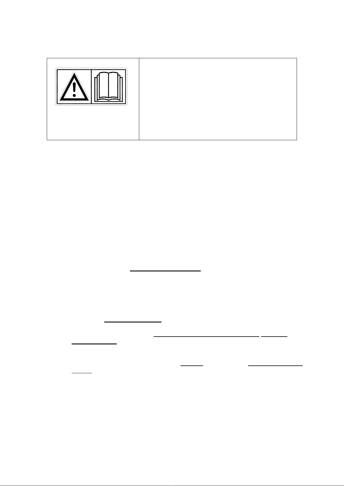
! SAFETY INSTRUCTIONS !
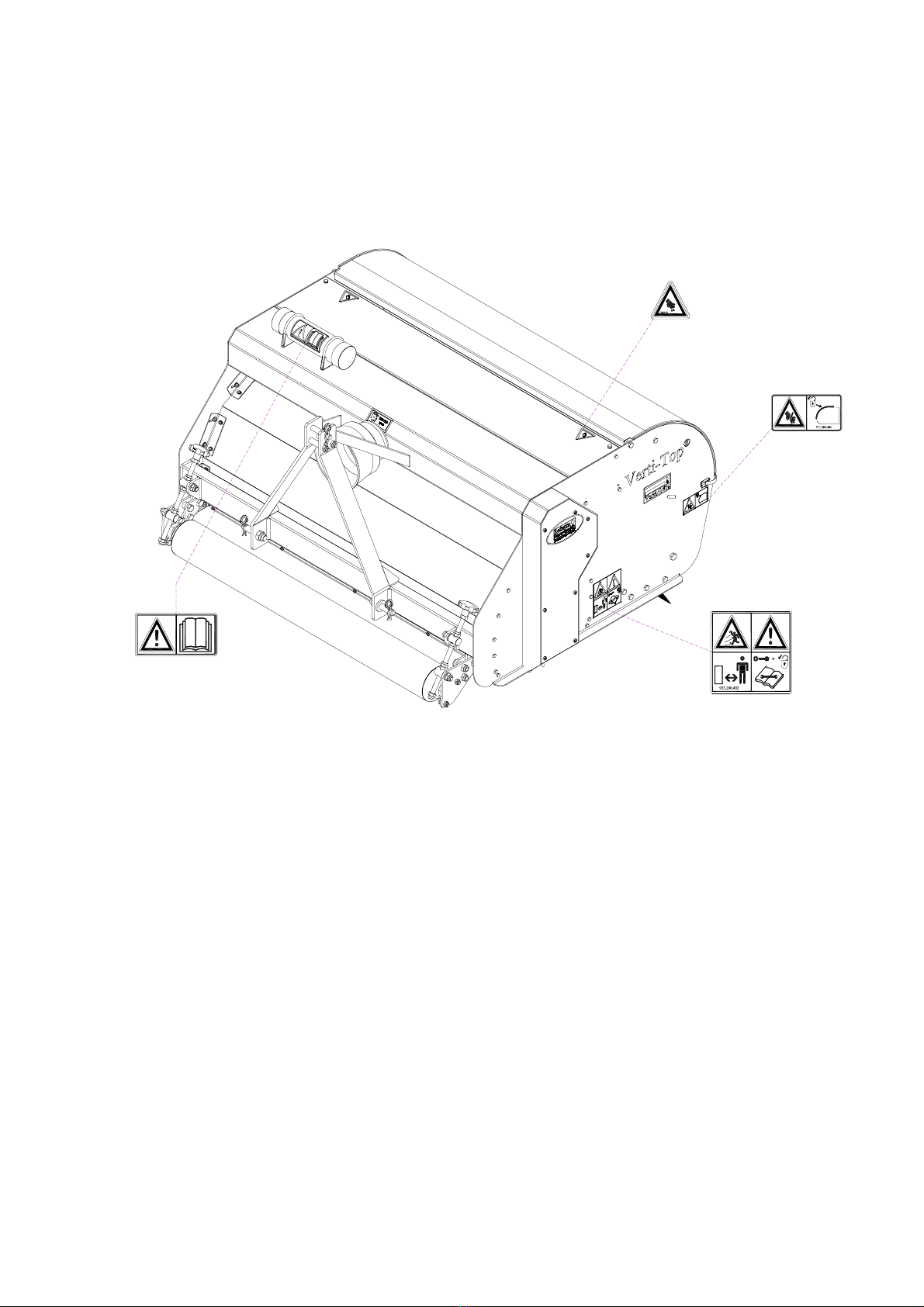
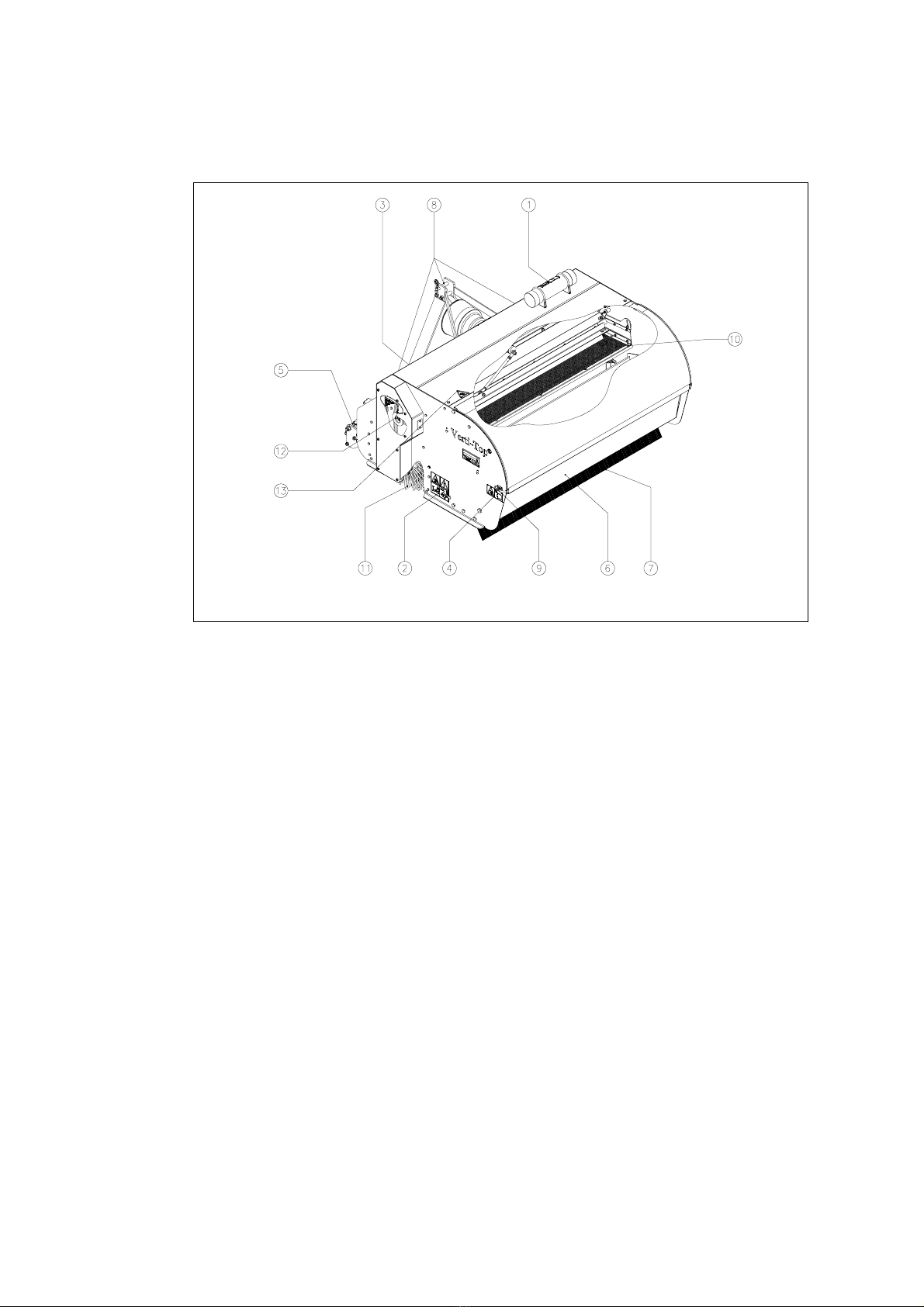
Fig. 1
The design of the Verti-Top allows for safe use.
However, this is only possible if the user fully
observes the safety instructions given in this
manual.
Read and understand (Fig. 1) the manual before
starting to use the Verti-Top.
If the machine is not used as described in the
manual, injury and/or damage to the Verti-Top
may result.
(1) The machine must only be used by professionals and must first be professionally
adjusted for use on the ground that is to be treated.
The manufacturer does not accept any liability with regard to damage resulting
from non-professional use; all resulting risks are the responsibility of the user.
Correct/professional use also includes following the manufacturer’s instructions
for use, maintenance and repair.
Before using the Verti-Top, inspect the area to be treated.
Remove any loose obstacles and avoid irregularities.
(2) The Verti-Top was constructed according to the latest technological knowledge
and is safe to use.
Improper use, maintenance or repair of the machine may result in injury to both
the user and others. This should be avoided!
Always use the Verti-Top in combination with the proper tractor as described in
the technical data.
(3) All persons whom the owner assigns to operate, maintain or repair the Verti-Top
must read and have completely understood the operating manual and in particular
the section Safety Instructions.
The user is responsible for a safe tractor/Verti-Top combination. This unit
must be tested in terms of noise, safety and ease-of-use. In addition, user’s
instructions must be prepared.
(4) Before using the Verti-Top, the user is obliged to inspect it for visible damage and
defects.
Any changes in the Verti-Top (including its functioning) that may affect its safety
must be corrected immediately.
For reasons of safety, it is in principle forbidden to make changes in or additions
to the Verti-Top (with the exception of those approved by the manufacturer).

4
If any modifications have been made to the Verti-Top, the present CE certificate
becomes null and void and the person who made the modifications should
himself make sure a new CE certificate is granted.
Before each use, inspect the Verti-Top for loose bolts/nuts/parts.
If present, inspect the hydraulic hoses regularly and replace them if they are
damaged or show signs of wear. The replacement hoses must meet the
manufacturer’s technical specifications.
Always relieve the pressure from the hydraulic installation, if present, before
carrying out any work on it.
NEVER use de Verti-Top if its protective covers and safety decals are missing.
During use of the Verti-Top the inspection panel MUST be closed. (Fig. 2)
Fig.2
Fig. 3
When opening the inspection panel BE CAREFUL not to get pinched (Fig. 3).
NEVER crawl underneath the Verti-Top.
If you need to access the bottom, tilt the Verti-Top.
NEVER step off the tractor while the engine is still running.
When carrying out maintenance, adjustments or repairs, make sure the Verti-Top
is blocked from sagging/moving/sliding.
When carrying out any maintenance activities, adjustments or repairs,
always switch off the tractor engine first, remove the tractor key from
the ignition and disconnect the PTO (Fig.4).
Fig.4
When carrying out any maintenance or repairs, make sure to use original Verti-
Top parts only. This will ensure continued safety of the machine and its user.

5
Only authorised technical personnel may carry out adjustments and repair work to
the Verti-Top.
Keep an overview of repairs.
(5) In addition to the instructions in this user manual, the generally applicable
regulations with respect to safety and working conditions must be observed.
For use on public roads the relevant traffic rules also apply.
Transporting persons is not permitted!
Do not use the Verti-Top when it is dark, during heavy rain/ storms, or on slopes
with a gradient greater than 20 degrees.
(6) Before starting to work, all persons who will operate the Verti-Top must be familiar
with all its functions and controls.
Attach the Verti-Top according to the instructions on the tractor.
(Danger of injury!)
Before driving off, make sure you have a clear view both nearby and far away.
On both sides of the Verti-Top, safety stickers (Fig. 3, 4, 5) have been applied to the
sideboards and to the back cover (Fig. 7) showing these warnings. Make sure these
safety stickers are always clearly visible and legible. Replace them if they are
damaged.
During operation, make sure there are NO persons in the danger area of the
Verti-Top to prevent them from getting injured by ejected material (Fig. 5).
Fig. 5
Fig.6
Keep a distance of at least 4 metres! (Fig. 6)

6
Be aware of the maximum lifting capacity of the towing vehicle.
Wear suitable clothing. Wear sturdy shoes with a steel tip, wear long trousers, do
up long hair and wear no loose clothing.
Fig. 7
(7) Location of safety stickers (Fig. 7)

7
CONTENTS
Section Description
Page
Foreword 2
Guarantee conditions 2
Registration card 2
Safety instructions 3
1.0 Technical data 8
2.0 First installation, removing the machine from the pallet 9
3.0 General parts list 10
4.0 The PTO 11
4.1 Length of the PTO 11
4.2 Operation of the PTO 12
4.3 PTO information and maintenance 12
5.0 Connecting to the tractor 13
6.0 Adjusting the working depth 14
7.0 Angle adjustment of the sieve 14
8.0 Transportation of the Verti-Top 15
9.0 Driving speed 15
10.0 Operation of the Verti-Top 15
11.0 Start/stop procedure 16
12.0 Emptying the waste container 17
13.0 Operation of the Verti-Top 18
14.0 Troubleshooting 19
15.0 EU certificate 19
16.0 Maintenance 20
16.1 Adjusting V-belt tension 21
16.2 Adjusting brush guideplates 22
16.3 Exchanging the sieve 23
Parts pages

8
1.0 TECHNICAL DATA
Model 1500
Working width 1.47 m (57.8”)
Working depth (with new brush) 0 mm - 26 mm (0”-1.02”)
Driving speed
Max. 12 km/h (7.5 mph)
Weight 360 kg (793.7 lbs)
Recommended tractor 25 HP with minimum lifting capacity of 400 kg
(881.9 lbs)
Volume of waste container 170 litres (6.0 cu. ft.)
Maximum capacity
(Theoretically at maximum speed, 12 km/h
(7.5 mph))
17,616 m2/h (129,921 ft2/h)
Mesh width of sieve
(Included standard) 0.2 x 5mm (0.2”x 16”)
Shipping dimensions L x W x H
1309 x 1682 x 1050 mm
51.5” x 66.2” x 41.3”
Three-point connection CAT. 1
Gearbox oil SAE 90
Lubricant EP 2
Standard parts Front and back roller.
Sieve, adjustable for degree of cleaning.
Pivoting waste container.
Adjustable brush guide covers.
Integrated surface-following drag brush.
PTO shaft.
Manual container.
Options Sieve elements with various opening sizes.

9
2.0 FIRST INSTALLATION, REMOVING THE MACHINE FROM THE
PALLET
Fig.8
The machine is standing vertically on the pallet. To remove the pallet and lay the machine
horizontally on the ground, proceed as follows (see Fig. 8):
*!! DO NOT CRAWL UNDER THE MACHINE !!
1. Open the covers 1 on both sides of the Verti-Top.
2. Open the inspection panel 2 and lock it in retaining strip 3.
3. Mount a cable to the lifting points 4 on both sides of the machine.
* Make sure that the cable/crane/lift can lift at least 600 kg (1,323 lbs).
4. Raise the machine, including the pallet, approx. 50 mm (2”) from the ground.
5. Make sure that the machine is on the point of the pallet 5.
6. Gently lower the machine, in a controlled way, until it fully rests upon the ground.
*!! BE CAREFUL – KEEP YOUR DISTANCE – THE MACHINE MAY SHIFT !!
7. Remove the top rod pin 6 and carefully rotate the pallet around the bottom 3-point pins 7 until
they are resting on the ground.
8. Remove the bottom three-point pins 3 and remove the pallet.
9. Connect the machine to the tractor (see section 5.0).
* Use the correct tractor. See the specifications.
10. Switch off the tractor and lock the tractor/Verti-Top combination to prevent it
from driving/sliding away.
11. Adjust the PTO to the Verti-Top tractor combination (See section 4.0).

10
3.0 GENERAL PARTS LIST
Figure 9 shows some important parts:
Fig. 9
1. Safety sticker 900.280.402: read user manual before use/toolbox.
2. Safety sticker 933.280.402: keep a distance of at least 4 metres from the
machine. Stop the engine before carrying out repairs or adjustments. Be careful of
flying debris.
* Make sure all safety stickers are clearly visible on the machine and are
understood.
3. The serial number is located on the front of the machine.
4. Safety sticker 911.280.404: the inspection panel MUST be closed during use.
5. Adjustable front roller for working-depth adjustment.
6. Pivoting waste container.
7. Surface-following drag brush.
8. Three-point fastening pins.
9. Closure for inspection cover.
10. Sieve, adjustable for degree of cleaning.
11. Rotating brush.
12. Adjustable belt tensioner for rotating brush drive.
13. Safety sticker 900.280.404: BE CAREFUL not to get pinched.

11
4.0 The PTO
The PTO is a very important part. It provides the drive from the tractor and ensures safe use of the
machine – if installed, used, and maintained correctly. The PTO has its own CE certificate. Make
sure to read the PTO manual. It is located on the PTO itself.
Fig. 10
4.1 LENGTH OF THE PTO (fig. 10)
The length of the PTO is very important. If it is too long, it may damage the drive of the tractor and/or
the Verti-Top.
If the overlapping length of the sleeves is, at any time, shorter than 150 mm, the PTO may be
damaged.
*!! The length will vary when the machine is raised or if another tractor is used !!
To make sure the length of the PTO is correct, after purchase or when using another tractor, carry
out the following steps:
1. Connect the Verti-Top to the tractor, as described in section 5.0.
2. * !! Switch off the tractor and make sure the tractor is properly blocked and cannot start
moving by itself !!
3. Lower the Verti-Top to the ground until the front and rear rollers just touch the ground.
4. Measure the distance between the PTO connection of the tractor and that of the Verti-Top, from
one furrow to the next.
5. Measure the distance B of the PTO at its shortest position, from locking pin to locking bolt.
6. Split the PTO in two and remove the protective cover from both ends.
7. Both the sleeve ends and the cover ends have to be shortened: (B-A) + 75 mm (3”).
8. Debur, grease, and assemble all parts.
9. Mount the PTO with the breaking bolt side facing the Verti-Top.
10. Mount the other end of the PTO to the tractor.
11. Check the overlap of the sleeves.
* !! Never use the machine if the protective cover of the PTO is damaged.
Replace it first. !!

12
4.2 OPERATION OF THE PTO
To ensure correct operation of the PTO, check the following items:
1. During operation of the Verti-Top, the angle between the points of rotation may not
exceed 30 degrees.
2. The rotating points should be aligned.
3. The overlap of the sleeves must be at least 150 mm.
4. Never use the machine if the protective cover of the PTO is damaged.
4.3 PTO INFORMATION AND MAINTENANCE
Summarised PTO maintenance schedule.
Periodic maintenance:
−Grease the lubricating points after every 100 hours of operation or when the PTO has
not been used for a while.
−Check the PTO for signs of damage to the protective covers and replace these if
necessary.
−Make sure all safety stickers are present on the PTO and that they are undamaged.
Annual maintenance:
−Remove the PTO from the machine.
−Carefully check all parts of the PTO.
−Replace all parts that are damaged.
−Lay out all the parts and check them carefully.
If any parts show signs of damage or wear, replace them.
−Clean all parts that interlock or engage.
−Reassemble the parts.
−Grease both sleeves and reassemble the two PTO halves.
−Reassemble the PTO and mount it on the machine.
For further information concerning maintenance and assembly of the PTO, please refer to the
manual included with the PTO.
@ If the PTO was shortened incorrectly, or if another tractor was used, the gearbox may be
overloaded. This may result in damage.

13
5.0 CONNECTING TO THE TRACTOR
Inspection procedure before connection of the Verti-Top:
−Visually inspect the Verti-Top for signs of damage and repair these if they
endanger a safe operation of the machine.
−Make sure that all nuts and bolts are properly tightened.
−Check whether all of the protective covers and safety stickers are present on
the machine and undamaged.
The machine may NEVER be used if this is not the case.
Fig. 11
The Verti-Top is connected to the tractor by means of the three-point connection.
This is done as follows: (Fig. 11)
1. Remove the three-point pins 1 and 2
2. Mount the PTO with the breaking bolt side facing the PTO shaft of the Verti-
Top.
3. Drive the tractor carefully in reverse so that the low connection arms can be
connected to the frame.
4. *!! Ensure that the tractor is well blocked and cannot start moving by itself !!
5. *!! Switch off the tractor before getting off !!
6. Connect the lower connecting arms to the three-point connecting plate pins 1
and secure these using the safety pins included.
7. Set the tractor’s stabiliser to 100 mm of lateral movement.
8. Mount the top rod of your tractor and pull it out by turning it until it has reached
the same level as the three-point stop connection of the Verti-Top.
9. Connect the top rod 3 with pin 2 to the frame. Secure pin 2 using the safety
pin included.
10. Push the top rod in by turning in order to tension it.
11. Mount the PTO to the PTO shaft of the tractor.
12. *!! Make sure that all mounting pins are securely locked!!
13. Start the tractor and raise the Verti-Top from the ground.

14
6.0 ADJUSTING THE WORKING DEPTH
The working depth can be adjusted by turning the star knobs 4 (Fig. 11) on the front of the
machine to adjust the front roller.
Set both sides of the machine to the same height so the field will be cleaned as evenly as
possible.
NEVER adjust the machine in such a manner that the ground surface might be damaged.
*! IMPORTANT!
First check the working depth while the machine is stationary before using the
machine!
7.0 ANGLE ADJUSTMENT OF THE SIEVE
Fig. 12
If too much material is collected in the waste container, while it should have passed through
the sieve, it is possible to give the sieve more time to sift out the material.
This can be achieved by setting the sieve at an angle.
This works as follows (see Fig 12):
*!! Ensure that the tractor/Verti-Top is well blocked and cannot start moving by itself !!
*!! Switch off the tractor before getting off !!
1. Open the covers 1 on both sides of the Verti-Top.
2. Open the inspection panel 2 and lock it in retaining strip 3.
*!! Make sure the inspection cover is secured properly and cannot fall closed!!
3. Loosen the bolts/nuts 4 on both sides of the machine.
4. Adjust the sieve 5 to the same angle on both sides.
5. Tighten the bolts/nuts 4 on both sides of the machine.
6. Unlock the inspection cover 2 from the retaining strip.
7. Carefully close the inspection cover 2.
8. Lock the inspection cover 2 with the closures 1 on both sides of the machine.
@ If more aggressive cleaning is desired, the bolts and nuts 4 can be repositioned in
holes 6. This allows the sieve to be adjusted upward an additional 5 degrees.

15
8.0 TRANSPORTATION OF THE VERTI-TOP
The user is responsible for the transport of the Verti-Top behind the tractor when travelling
on public roads. Check the national traffic rules.
In view of the weight of the Verti-Top, a maximum speed of 20 km/h (12.4 mph) should be
observed while driving in open fields with the machine raised.
Higher speeds may endanger the driver and/or other people and even damage the machine.
* When the machine is in the raised position, at least 20% of the weight of the
tractor should be supported by the front axle.
9.0 DRIVING SPEED
The driving speed is limited to 12 km/h (7.5 mph).
Higher speeds are not recommended in view of excessive wear and damage that may occur
to the machine and the ground underneath.
10.0 OPERATION OF THE VERTI-TOP
Before the Verti-Top is used in the field, the following should be checked:
1. Are there any loose objects in the field? Remove these first.
2. Are there any slopes? The maximum slope this machine can work on is 20
degrees.
Always work downhill.
3. Is there any danger of flying objects, such as balls, which may distract the
attention of the driver? If so, do NOT use the Verti-Top.
4. Is there any danger of sinking or sliding away? If so, postpone the work until the
conditions are more favourable.
5. If the soil is very wet, the work should be postponed until the conditions are more
favourable.
6. If the machine vibrates excessively, reduce the PTO speed.
7. A field can be done 2 or 3 times in the same direction or different directions to
achieve better cleaning.
8. Do not make sharp turns; preferably drive in straight lines to avoid damaging the
machine and/or the ground.

16
11.0 STARTING/STOPPING PROCEDURE
The starting procedure is VERY important. If this procedure is not followed exactly as described
below, serious damage may occur to the ground underneath the machine.
The start procedure is as follows:
1. Check the Verti-Top thoroughly for lose parts and make sure all parts function properly.
*!! If parts are found that are loose or do not function properly, correct the situation before
using the Verti-Top!!
2. Drive to the place where the soil is to be treated.
3. Adjust the working depth while the machine is stationary as described in section 6.0.
*!! Ensure that the tractor is well blocked and cannot start moving by itself !!
*!! Switch off the tractor before getting off !!
4. Lower the machine until it hangs approximately 50 mm above the ground.
5. Shift the tractor to the correct gear.
6. Switch on the PTO at a low speed (rpm).
7. Slowly raise the PTO speed to approx. 300 rpm.
8. Drive the tractor forward and lower the Verti-Top smoothly onto the pre-adjusted rollers.
9. Raise the PTO speed to a maximum speed of 500 rpm.
10. Increase the driving speed to a maximum of 12 km/h (7.5 mph).
Stopping is done as follows:
1. While still moving, raise the machine smoothly until it is approximately 50 mm above the
ground.
2. Disengage the PTO and raise the machine further.
3. Drive to the following location and begin again as described above.

17
12.0 EMPTYING THE WASTE CONTAINER
Fig. 13
When the waste container is full it must be emptied.
This is done as follows (see Fig. 13):
1. Drive the Verti-Top to the dumping location for collected waste.
*!! Ensure that the tractor is well blocked and cannot start moving by itself !!
*!! Switch off the tractor before getting off !!
2. Open the covers 1 on both sides of the Verti-Top.
3. Open the inspection panel 2 and lock it in retaining strip 5.
*!! Make sure the inspection cover is secured properly and cannot fall closed!!
4. Remove pins 3 along with the safety clips from the side panels of the machine.
5. Carefully tip the waste container 4 until it rests again the bottom stoppers.
6. Remove the waste from the waste container 4.
7. Tip the waste container 4 back into the upright position.
8. Install pins 3 and the safety clips.
9. Unlock the inspection cover 2 from the retaining strip.
10. Carefully close the inspection cover 2.
11. Lock the inspection cover 2 with the closures 1 on both sides of the machine.
@ Dispose of the waste in the manner prescribed by local regulations.

18
13.0 DISCONNECTING THE VERTI-TOP
Fig. 14
The machine can be disconnected from the tractor as follows (See Fig 14):
1. Drive the Verti-Top up to its storage place, which must have a stable and flat ground.
*!! Ensure that the tractor is well blocked and cannot start moving by itself !!
*!! Switch off the tractor before getting off !!
2. Loosen the front roller adjustment 4 to lower the roller as far as possible.
3. Carefully lower the Verti-Top onto the ground.
4. Release the top rod 3.
5. Remove the safety pin from pin 2. Remove the pin from the top-rod connection.
6. Disconnect the PTO 5.
7. Remove the safety pins from pins 1 and remove the pins.
8. *!! Make sure the Verti-Top is stable and cannot roll/slide away!!
9. Start the tractor and drive it away from the machine.
@ While placing in storage it is recommended that the brush not be allowed to
touch the ground or other objects in order to prevent the bristles from being
bent.

19
14.0 TROUBLESHOOTING
Problem Possible cause Solution
Too much material is
collected in the waste
container.
PTO rpm too high.
Sieve angle set too low.
Working depth is set too
deep.
Sieve is blocked.
Lower PTO speed.
Increase angle of sieve. (see
section 7.0).
Decrease the working depth.
Clean the sieve.
Too little cleaning Working depth is not set deep
enough.
Driving speed is too high.
Brush is worn.
PTO speed is too low.
Outlet opening for brush is
blocked.
V-belts are slipping.
Increase the working depth.
Lower driving speed.
Adjust guide covers (see section
16.2)
Replace brush.
Increase the PTO speed.
Remove blockage.
Tighten V-belts (see section
16.1).
Poor appearance of field after
completion.
Working depth is set too
deep.
Drag brush damaged.
Decrease the working depth.
Replace or repair.
Sieve bumps against side
plates. Incorrect alignment of sieve.
Centre the sieve.
Cracking noises during use of
the machine. Bearings require lubrication
or are worn.
Lubricate the bearings with an
EP2 grease or replace the
bearings.
15.0 EU CERTIFICATE
We, Redexim BV, Utrechtseweg 127, 3702 AC Zeist, The Netherlands, declare entirely on
our own responsibility that the product
VERTI-TOP WITH MACHINE NUMBER AS INDICATED ON THE MACHINE AND IN THIS
MANUAL,
to which this declaration applies is in conformity with the standards NEN-EN-ISO 12100-1,
NEN-EN-ISO 12100-2 and NEN-EN 294 in accordance with the stipulations of the machine
directive 98/37/EC.
A.C.Bos
Manager Operations & Logistics
Redexim Holland

20
16.0 MAINTENANCE
Time schedule Check point/lubricating point Method
Before each use Check for loose bolts/nuts.
Presence and legibility of safety
stickers (Fig. 5)
Tighten the loose bolts/nuts
with the correct torque.
Replace if damaged or missing.
After first 20 operating hours
(new or repaired) Lubricate the roller bearings for
the front and rear rollers of the
driveline.
Check for loose bolts/nuts.
Check the tension of the V-
belts.
Use EP 2 lubricating grease.
Tighten the loose bolts/nuts
with the correct torque.
Adjust the tension of the V-
belts if necessary. (see section
16.1)
After every 100 hours of use
or annually Lubricate the roller bearings for
the front and rear rollers of the
driveline.
Check the gearbox for oil
leakage.
Check the oil level in the
gearbox.
Check for loose bolts/nuts.
Check the tension/wear of the
V-belts.
Check the wear of the brushes.
Inspect and lubricate the PTO.
Use EP 2 lubricating grease.
Repair or replace.
If necessary, fill to the level of
the fill opening.
Tighten the loose bolts/nuts
with the correct torque.
Adjust the tension of the V-
belts. (see section 16.1).
Or, if necessary, replace the V-
belts.
Rotating brush:
If necessary, adjust the
guideplates inward. (see
section 16.2).
If the adjustment limit has been
reached, replace the brush.
Drag brush:
Replace or repair.
See instruction manual for
PTO.
Table of contents
Other Redexim Cleaning Equipment manuals