Redwood Forst ST6p User manual

Redwood Global Ltd,
Unit 86, Livingstone Road, Walworth Business Park, Andover,
Hampshire. SP10 5NS. United Kingdom
pWoodchipper
USER MANUAL
ENGLISH
21/11/2018 Revision 3

P a g e | 1
Table of Contents
Introduction............................................................................................................................................3
Purpose of machine.............................................................................................................................4
Safety.....................................................................................................................................................7
Safe working .....................................................................................................................................7
Machine lifting...................................................................................................................................8
DOs and DON’Ts .............................................................................................................................9
Noise test information........................................................................................................................10
Machine operation..............................................................................................................................11
Machine control panel, start/stop & operating settings ............................................................12
Ignition switch .................................................................................................................................12
Emergency Stopping –Standard Program ....................................................................................15
Emergency Stopping –Orange Button Program...........................................................................16
Feed jam & blockages.......................................................................................................................17
Transportation.....................................................................................................................................18
Attaching to the vehicle tow hitch ................................................................................................19
Unhitching the machine.................................................................................................................19
Routine maintenance.........................................................................................................................20
Engine maintenance......................................................................................................................21
Fastener tightening torques..........................................................................................................21
Service schedule............................................................................................................................22
Covers: engine, chipping chamber, side panels.................................................................24
Engine bay ......................................................................................................................................25
Blade changing……………………………………………………………….…………………...27
Blade sharpening ...........................................................................................................................28
Hydraulic oil filter............................................................................................................................29
Battery..................................................................................................................................................32
Battery safety information.............................................................................................................32
Storage and transport....................................................................................................................32
Initial operation ...............................................................................................................................32
Battery removal & maintenance...................................................................................................32
Charging..........................................................................................................................................33
Jump starting...................................................................................................................................33
Taking battery out of service ........................................................................................................34
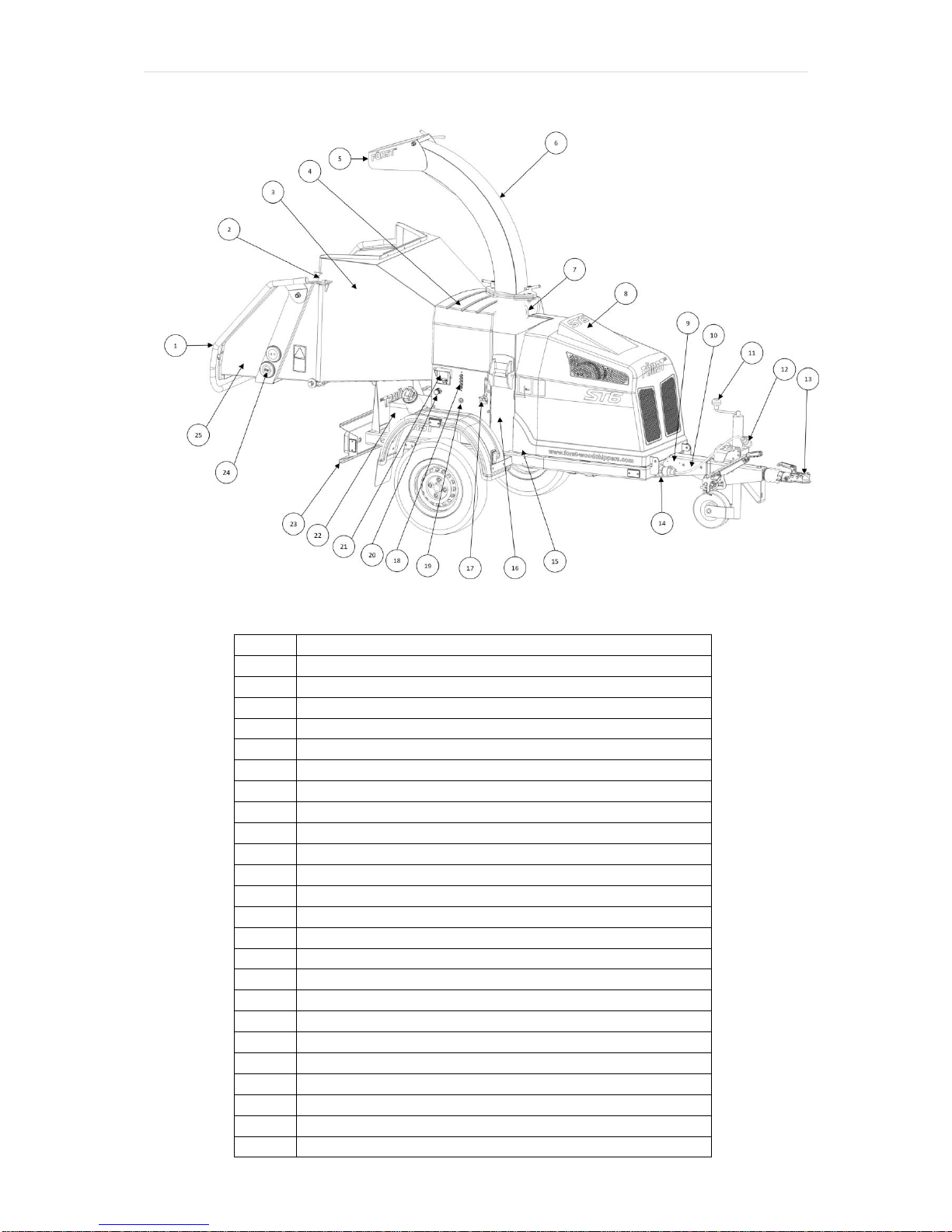
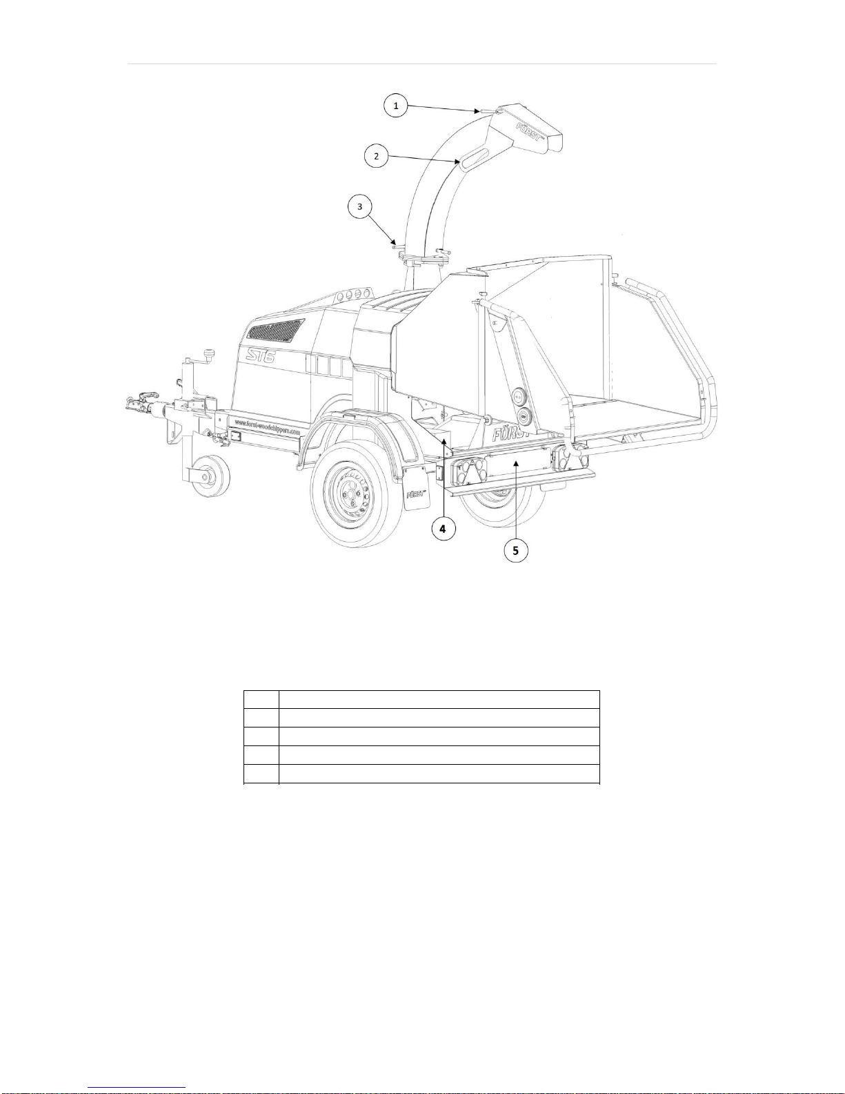
Parts lists.............................................................................................................................................35
Hopper tray touch sensor..........................................................................................................35

P a g e | 2
Chipping chamber assembly........................................................................................................36
Chipping chamber assembly - Bottom feed...............................................................................36
Chipping chamber assembly –Bottom feed & Anvil.................................................................38
Chipping chamber assembly - Drive..........................................................................................39
Chipping chamber assembly - Flywheel drive..........................................................................40
Chipping chamber assembly - Bottom feed roller cover..........................................................41
Chute assembly............................................................................................................................42
Top feed roller assembly...............................................................................................................43
Flywheel assembly.........................................................................................................................44
Fuel Tank Assembly......................................................................................................................45
Hydraulic Pump Assembly............................................................................................................46
Light board assembly.....................................................................................................................47
Belt Tensioner assembly...................................................................................................................48
Running gear –hitch & axle..........................................................................................................49
Hydraulics circuit diagram.................................................................................................................49
Electrical circuit diagram –Mechanical & touch sensor hopper .................................................50
Decals....................................................................................................................................................50
Manufacturer’s Statutory Plate.........................................................................................................52
Warranty..............................................................................................................................................53
CE Certificate......................................................................................................................................54

P a g e | 3
Introduction
Thank you for becoming the owner of this Redwood Global Ltd, Forst ST6p
woodchipping machine. By observing the contents of this manual, we hope the
machine gives safe and productive service. This user manual is intended for the
owner/operator to safely and effectively operate this machine and carry out routine
maintenance between services. This is not a comprehensive service manual. See
Service Schedule for routine maintenance and when to take the machine to a service
specialist. For engine maintenance, please refer to the engine manual supplied with
this machine.
This machine has been through a pre-delivery inspection before leaving the factory
and is ready to use.
Before use and as a minimum, the safety and machine operation
sections covered on pages 4 to 19 must be read and understood.
Failure to do so could result in serious injury or loss of life to the
operator and others nearby.Also, damage to property and this machine may
occur. Please observe and obey all warning signs (decals) located on the machine.
Their meaning is covered in this manual under decals.
All personnel working with this machine must be adequately trained in its use and
most importantly, follow the advice on safe working practices.
Redwood Global Ltd endeavour to continuously develop and improve its products.
They reserve the right to make changes at any time, without notice or incurring any
obligation.
Continuous improvement will affect machine design and production so there may be
minor discrepancies between the actual product and this manual.
This manual must remain with the machine for reference by operators and includes
hiring or if the machine is resold.

P a g e | 4
Purpose of machine
The Forst ST6p is designed to reduce wood material up to 150mm diameter to
woodchip. This machine is capable of processing up to 5 tonnes of wood per hour.
Engine
Briggs Vanguard V twin EFI
Roller feed
Twin series hydraulic motors
Maximum power
27.2 kW (37hp)
Maximum material diameter
150mm
Cooling method
Air cooled
Fuel capacity
30 litres
Overall weight
745kg
Hydraulic oil capacity
18 litres
Starting method
Electric
Material processing capacity
5 Tonnes/Hr
Fuel type
Petrol

P a g e | 5
Exterior component identification
Figure 1
1
TRIP BAR
2
HOPPER TRAY LATCH
3
HOPPER
4
CHIPPING CHAMBER COVER
5
CHUTE HOOD
6
CHUTE
7
MACHINE LIFTING EYE
8
ENGINE COVER
9
MANUFACTURER'S STATUTORY PLATE
10
SERIAL NUMBER
11
JOCKEY WHEEL HANDLE
12
VEHICLE CONNECTION LEAD
13
TOW HEAD
14
MACHINE LIGHT BOARD SOCKET
15
ENGINE COVER LATCH
16
CHIPPING CHAMBER
17
THROTTLE
18
GREASE POINT
19
IGNITION SWITCH
20
CONTROL VALVE FEED SPEED ADJUSTMENT
21
CONTROL PANEL
22
FUEL TANK
23
LIGHT BOARD
24
FEED START/STOP TOUCH SENSORS
25
HOPPER TRAY

P a g e | 6
Figure 2
1
CHUTE HOOD LOCK HANDLE
2
CHUTE HANDLE
3
CHUTE ROTATION LOCK HANDLE
4
BATTERY
5
REMOVEABLE NUMBER PLATE HOLDER
6
7

P a g e | 7
Safety
Safe working
Before using this machine, make sure that you are trained and fluent in its operation.
Know the location of and how to use all the safety features. Know how to control the
feed and stop the machine in an emergency. Be familiar with the hazards and safe
working practices to prevent injury and damage to property and machine. Also be
aware of the legal restrictions for personnel and towing with vehicles.
1. The minimum age for service personnel is 18 years. Personnel aged 16 can
use the machine for training under supervision by a suitably trained person of
18 years or over.
2. Operators and personnel working with this machine must not be under the
influence of alcohol, drugs or medication that would impair judgement,
concentration or reaction times. Excessive tiredness is also a risk.
3. In use, woodchip and debris are ejected with considerable force from the
chute and can travel up to 10m. Make sure the chute directs woodchip to a
safe location so that no one can be harmed or property damaged. Do not
allow discharge to be directed onto roads or public rights of way.
4. Maintain a 10m exclusion zone around the machine and clearly mark if in a
public area. Keep this area free of material build up.
5. Make sure the machine is on even, level and stable ground and cannot move
or topple when in use. Use wheel chocks if necessary.
6. Keep children and animals well away from the working area.
7. The machine operator must wear protective equipment:
a. Chainsaw safety helmet (EN 397) with mesh visor (EN 1731)
b. Correctly rated ear defenders (EN 352)
c. Work gloves with elasticated wrist bands.
d. Steel toe cap boots (EN345-1)
e. Close fitting heavy duty non-snag clothing. Hi-viz clothing (EN 471) if
needed.
f. Protect breathing with a face mask if appropriate. Some plant material
can give off harmful dust and poisonous vapours. This may cause
respiratory problems or serious poisoning. Check the material to be
processed before starting.
g. DO NOT wear rings, bracelets, watches, jewellery or anything that
could be caught on the material being fed and draw you into the
machine.

P a g e | 8
8. All personnel operating or feeding material into the machine must wear heavy
duty non-snag clothing to help prevent being caught on material and drawn
into the machine. The feed mechanism of this machine uses high powered
hydraulic motors to drive sharp toothed rollers that feed material into the
cutting blades. DO NOT take risks with it. NEVER ASSIST ANY MATERIAL
INTO THE FEED ROLLERS WITH HANDS OR FEET.Use the wooden
paddle or further long material if necessary.
9. Never climb onto the hopper area while the machine is in operation.
10.CAUTION! –Keep hands and feet outside the hopper. Do not attempt to force
material into the machine by hand –use a piece of wood if necessary.
11.Material can be forcibly ejected from the hopper towards the operator. Ensure
full head and face protection is worn.
12.Very twisted material should be trimmed into manageable pieces. Failure to
do this can result in material extending outside the hopper, moving
aggressively side-to-side creating a hazard to the operator.
13.Do not try to force material over 150mm in diameter into the machine.
14.Carefully site the machine so operators can work furthest from any local
danger. For example, on a road side, place machine so operators work on
the verge and not in the road exposed to traffic.
Machine lifting
The lifting eye is designed for securely holding the machine’s weight only. Do not
use hoist hook directly on the lifting eye. Use a correctly rated safety shackle.
Inspect lifting eye before each use and do not use if damaged.
Figure 3

P a g e | 9
DOs and DON’Ts
DO stop the machine before making
any adjustments, refuelling or
cleaning.
DO make sure the machine has
stopped rotating and remove the
ignition key before any maintenance or
the machine is left unattended.
DO ensure that the machine is level,
well supported and cannot move
during use.
DO run the machine at full throttle.
DO conduct regular machine checks
for visual fluid leaks.
DO take regular breaks. Wearing
protective equipment can be hot and
tiring leading to a lack of
concentration, increasing the risk of
having an accident.
DO keep hands, feet and clothing out
of feed area, chute and moving parts.
DO NOT use machine in poor visibility
or insufficient light to see clearly.
DO NOT use or attempt to start the
machine without the discharge chute
or guards correctly and securely fitted.
DO NOT stand directly in front of the
in-feed hopper when using the chipper.
Stand to one side.
DO NOT allow the following to enter
the machine as damage is likely:
BRICKS
METAL
STRING
GLASS
CLOTH
RUBBER
PLASTIC
ROOTS
STONES
BEDDING
PLANTS
DO NOT stand in front of the chute.
DO NOT smoke when refuelling.
Petrol fuel is highly flammable and
explosive in certain conditions.
DO NOT let anyone who has not
received instruction, operate the
machine.
DO NOT climb on the machine at any
time except for a tracked machine
ride-on plate where fitted.
DO NOT handle material partially
engaged in the machine while in
operation.
DO NOT touch any exposed wiring
while the machine is running.

P a g e | 10
Noise test information
Machine
Forst ST6p
Notes
Tested chipping 50 x 50mm sawn pine 4.2m in length.
Noise levels above 85dB (A) will be experienced at the working position and within a
4 metre radius. Operators and personnel within a 4 metre radius must wear
appropriate ear protection at all times while machine is in operation to prevent the
risk of hearing damage.
A-weighted emission sound pressure (beside operator’s ear) LpA = 106.3dB(A).
Peak C-weighted instantaneous sound pressure (beside operator’s ear) LCpeak =
128.4dB(C). Results at 10 metre radius are calculated.
Guaranteed sound power: 118dB(A)
As required by Machinery Directive 2006/42/EC “Noise Emission in the environment
by equipment for use outdoors.”

P a g e | 11
Machine operation
STANDARD PROGRAMME
MACHINE USE
TOUCH SENSOR HOPPER
STAGE
1 Fold down hopper tray
Start engine.
2
Turn key to start engine and let go once
engine has fired
3
Allow engine to run for 30 seconds then
open throttle to full
4
For forward feed, touch green button
twice
5 Feed material
6
To stop, touch red button or push trip bar
7
To reverse feed, touch green button once
8 To stop machine
9 Touch red button or push trip bar
10 Close throttle to minimum
11 Switch off ignition and remove key
12 Before transporting machine
14 Sweep out debris from hopper
15
Close hopper tray by lifting fully up
against stops and engage latch
OrRANGE BUTTON PROGRAMME
MACHINE USE
TOUCH SENSOR HOPPER
STAGE
1 Fold down hopper tray
Start engine.
2
Turn key to start engine and let go once
engine has fired
3
Allow engine to run for 30 seconds then
open throttle to full
4
For forward feed, touch green button once
5 Feed material
6
To stop, touch e-stop button or push trip
bar
7
To reverse feed, touch orange button
once for short reverse or twice for
continual
8 To stop machine
9 Touch e-stop button or push trip bar
10 Close throttle to minimum
11 Switch off ignition and remove key
12 Before transporting machine
14 Sweep out debris from hopper
15
Close hopper tray by lifting fully up
against stops and engage latch

P a g e | 12
Machine control panel, start/stop & operating settings
This machine is fitted with an engine PLC (Programmable Logic Controller) system
that manages the engine, feed and all safety features. The control panel is located
on the right side panel (see Figure 1). Feed and engine speed are controlled with a
“No Stress” function ensuring that cutting conditions are kept within optimum limits.
This maximises throughput while minimising jams and blockages. There will be
times when material is being cut and the feed will momentarily stop until engine
speed increases. At this point, the feed will start without warning. Service warnings
shown below will be displayed at certain intervals. The engine will not start until OK
is pressed.
First 20 Hour Warning: "Change Hydraulic Oil Filter"
Every 20 Hour Warning: "Blade and Machine check required see manual"
50 Hour Service Warning: "1st Full Service recommended"
Every 200 Hour Service Warning: "Full Service recommended"
Using the control panel:
Ignition switch
Figure 4
Turn ignition key clockwise to first position to turn the ignition on.
1
KEY ROTATION IN SWITCH TO START
2
IGNITION SWITCH POSITIONS & FUNCTION
3
OFF
4
IGNITION
5
START

P a g e | 13
Turn ignition key fully clockwise to crank engine. Display will automatically go to P1
If engine fails to start, turn key to off position and start process again. P1 shows
Working Hours and charging indicator text at the screen bottom centre.
P2 shows I/O tests. Tests all functions and safety controls.
Pin screen
P3 shows No-Stress Settings
Actual RPM
Upper Band - 1450 RPM
Mid Band –1250 RPM
Lower Band –1050 RPM
Pin screen automatically displays if any setting changes are attempted.

P a g e | 14
P4 Crank Time –3
Feed speed adjustment
Figure 5
The feed speed can be adjusted to suit the material being chipped see Figure 5.
Turn dial to align number with pip. Set feed speed so that the No-Stress operates as
little as possible, this will give the highest throughput. When feeding Leylandii or
leafy material, set feed roller speed to 4.5.
To stop engine turn off with
ignition key by turning fully anti-
clockwise.
1
CONTROL VALVE FEED SPEED
ADJUSTMENT.
POSITION INDICATED BY PIP.
0 = MINIMUM
10 = MAXIMUM

P a g e | 15
Emergency Stopping –Standard Programme
Push the RED SAFETY BAR. This will stop the feed rollers instantly. The chipper
flywheel will still be turning. Turn the throttle lever to idle and switch off the engine
with the ignition key.
Before using the chipper every day
Start the machine with the ignition key on the control panel.
With the engine running at full speed tap the green button (3) once and the
rollers will go into reverse,
Tap the green button again and rollers will go into forward (chipping mode).
To stop the feed rollers either tap the red stop button (2) or push the red stop
bar (1) and the rollers will stop instantly.
If any of these functions fail, turn off the machine and remove the key from the
ignition switch and contact Redwood Global and ask for service.
1
Red Stop Bar
2
Red Stop Button
3
Green Forward and Reverse Button
4
E-Stop (if fitted)

P a g e | 16
Emergency Stopping –Orange Button Programme
Push the RED SAFETY BAR. This will stop the feed rollers instantly. The chipper
flywheel will still be turning. Turn the throttle lever to idle and switch off the engine
with the ignition key.
Before using the chipper every day
Start the machine with the ignition key on the control panel.
With the engine running at full speed tap the green button (3) and the rollers
will go into forward (chipping mode).
Tap the orange button and the rollers will go into a short reverse, tap it again
and the rollers will continue in reverse.
To stop the feed rollers push the red stop bar (1) and the rollers will stop
instantly and or push the e-stop button and whole machine will shut down.
If any of these functions fail, turn off the machine and remove the key from the
ignition switch and contact Redwood Global and ask for service.
1
Red Stop Bar
2
Orange Reverse Button
3
Green Forward Button
4
E-Stop

P a g e | 17
Feed jam & blockages
Be aware that whatever is fed into the machine has to come out of the chute.
Always monitor the state of chip flow out of the chute. If this stops, STOP FEEDING
MATERIAL IMMEDIATELY.Continuing to feed material will further compact a
blockage and make it more difficult to clear.
If the chipping chamber or chute become blocked:
1. Stop the engine and remove ignition key.
2. Remove chute and check that it is clear.
3. If the chipping chamber is blocked, open the engine cover, then chipping
chamber cover. DO NOT REACH INTO THE CHIPPING CHAMBER WITH
HANDS. Beware that the flywheel within the chipping chamber has two sharp
blades mounted on it and can move causing a serious injury risk. Wearing
protective gloves and using a piece of wood, carefully clean out the chipping
chamber.
If feed becomes jammed (see Figure 6):
1. Stop the engine and remove ignition key.
2. Open engine and chipping chamber covers.
3. Release feed roller spring tension on both sides by slackening off the eye bolt
nuts and remove if necessary.
4. Insert feed lift tool and lift top feed roller to fully open.
5. Insert M12 screw into side of feed chamber and screw completely in. Lower
top feed roller onto the screw to secure in the open position.
6. There should now be access to the feed chamber. Beware that this is the
machines cutting zone. The top and bottom feed rollers have sharp teeth and
the flywheel cutting blades are not far from them. DO NOT PUT HANDS
INTO THIS AREA. Wearing protective gloves and using a piece of wood,
carefully clear jammed material inside feed chamber.
7. When clear, lift top feed roller via lifting tool, remove top feed M12 securing
screw, lower top feed roller and remove lifting tool.
8. Re-assemble feed tensioner springs and replace covers.

P a g e | 18
Figure 6
Transportation
When towing the machine the maximum legal speed limit is 60mph.
On very rough and uneven road surfaces, reduce speed to protect the
machine from undue vibration.
When off road, avoid objects that may collide with the machine underside.
Avoid steep gradients when off road.
Avoid excessively pot holed ground.
Exercise caution when reversing the machine as the short wheel base will
react quickly to steering.
Keep tyre pressures inflated to 2.8 Bar or 41 psi.
Check wheel nuts are tightened to between 90Nm and 100Nm.
Clear machine of loose woodchip material before departing.
Ensure the chute is securely fixed at the inboard position before departing.
Ensure that the hopper tray is closed in the up position and the locking latch is
fully engaged before departing.
1
REMOVE EYE BOLT NUT BOTH SIDES
BEFORE LIFTING FEED ROLLER
2
INSERT TOP FEED ROLLER LIFTING TOOL
INTO SLOT AND LIFT
3
INSERT M12 SCREW TO HOLD FEED IN
OPEN POSITION

P a g e | 19
Attaching to the vehicle tow hitch
Check that the vehicle ball hitch is well greased.
Raise the machine hitch by turning the jockey wheel handle anticlockwise until
the hitch socket is above the vehicle hitch ball.
Reverse the vehicle until the ball is directly below the machine hitch socket.
Attach the breakaway cable/secondary coupling to a suitably strong point on
the vehicle, not the ball hitch.
Ensure the barrel lock is retracted from the tow head.
Grasp handle on tow head and push back catch with thumb.
Wind the jockey wheel handle clockwise to lower the hitch socket onto the ball
hitch.
Release tow head handle and continue to wind the jockey wheel handle
clockwise. The tow head should snap into place on the ball hitch. If it
doesn’t, repeat previous two steps.
Wind jockey wheel up until fully retracted and the jockey wheel frame is
seated in its notch on the stem. The machine’s weight should be fully on the
vehicle.
Release the jockey wheel clamp and slide the jockey wheel assembly fully up
then tighten clamp.
Connect the vehicle trailer socket to the machine socket with the connection
lead. Check all machine lights and tow vehicle lights are working correctly.
Insert the barrel lock for security.
The machine is now properly attached to the tow vehicle.
Unhitching the machine
Ensure the machine will not roll away after being disconnected from the tow
vehicle.
Disconnect the trailer socket from the tow vehicle.
Release the barrel lock.
Release the breakaway cable/secondary coupling.
Release the jockey wheel assembly clamp, fully lower the wheel and tighten
the clamp.
Wind the jockey wheel handle anticlockwise until it starts to take the machine
weight.
Grasp the tow head handle and release the catch with your thumb.
Wind the jockey wheel handle anticlockwise until the tow head is clear of the
ball hitch.
Drive the tow vehicle clear of the machine.
Level the machine by winding the jockey wheel handle.
The machine is now fully detached from the tow vehicle.
Table of contents