Reese 22K User manual

Y
t k it ith
INSTRUCTION MANUAL
22K - Fifth Wheel Hitch Product No.
30033
(1) Provide this Manual to end user.
(2) Physically demonstrate hitching and unhitching procedures in this Manual to end user.
(3) Have end user demonstrate that he/she understands procedures.
Y
ou can
t
a
k
e
it
w
ith
you.
DEALER/INSTALLER:
(1) Read and follow this Manual every time you use hitch.
(2) Save this Manual and Hitch Warning Hang Tag for future reference.
(3) Pass on copies of Manual and Hitch Warning Hang Tag to any other user or owner of hitch.
(4) Never remove hitch warning decals as shown on the cover of this manual. If damaged, contact Reese (1-888-521-0510 or
www.reeseprod.com) for free replacement decals.
END USER:
HITCH HANDLE
HANDLE LATCH
WARNING DECAL
WARNING DECAL JAWS TO HOLD
KING PIN
SKID PLATE
RAMP
WARNING HANG TAG
FUNNEL FOR
30033IN-OCT 28,2008 F PCN11465 ©2005 CEQUENT TOWING PRODUCTS, INC LITHO IN USA
For Installation Assistance or Technical Help, Call 1-888-521-0510
TRAILER KING PIN

WARNING:
Failure to follow these instructions may result in death or serious injury!
INDEX
1. GUIDELINES FOR MATCHING TOW VEHICLE AND TRAILER P. 2
2. ASSEMBLY INSTRUCTIONS P. 4
3. BEFORE EACH TRIP P. 5
4. HITCHING PROCEDURE P. 5
5. PULL TEST P. 8
6. UNHITCHING PROCEDURE P. 8
7. MAINTENANCE P. 9
8. REESE FIVE YEAR LIMITED WARRANTY P. 9
GUIDELINES FOR MATCHING HITCH TRUCK AND TRAILER
WARNING:
•Trailer and its contents together must not exceed truck, hitch and/or trailer tow
ratings.
•Towing vehicle must have a manufacturer’s rated towing capacity equal to or
greater than the gross trailer weight (dry weight of the trailer plus payload of the
trailer). (See Fig. 1)
•Gross weight of trailer must not exceed 22,000 pounds.
•King pin weight must not exceed 5,500 pounds (See Fig. 2). If in doubt have king
pin weight measured by qualified facility.
FACTORY TRAILER + FULL WATER TANKS + CARGO, ETC.
= GROSS TRAILER WEIGHT
Fig. 1
1. Reese hitches are designed for use with recreational fifth wheel trailers only. Hitch applications other than recreational fifth
wheel trailers must be approved in writing by Reese’s Engineering Department.
2. Use only a SAE 2-inch kingpin with your Reese Fifth Wheel Hitch.
3. Approximately 15%-25% of trailer weight should be on hitch (Pin Weight). See Fig. 2
15-25%
GROSS TRAILER
75
85%
Fig. 2
30033IN-OCT 28,2008 F PCN11465 ©2005 CEQUENT TOWING PRODUCTS, INC LITHO IN USA 2
GROSS
TRAILER
WEIGHT
(PIN WEIGHT)
75
-
85%
GROSS TRAILER
WEIGHT
GROSS TRAILER WEIGHT

4. Trucks come in many different configurations. Reese hitches are designed for use in light trucks such as the Ford F-
Series, the Chevy Silverado and the Dodge Ram. Reese recommends the use of long bed (8ft) light trucks for the best
combination in truck - trailer turning clearance.
Rule of thumb: The distance from the back of the truck cab to the center of the rear truck
axle (“X” in Fig. 3), should be approximately 4 inches greater than one-half
the trailer width (“Y” in Fig.3)
RV TRAILER
TRUCK
Fig. 3
KING PIN
5. The height of the hitch and the pin box should be adjusted so the trailer is approximately level as it is towed. Allow
approximately 6 inches clearance between the top of the pickup walls and the underside of the front of the trailer for pitch
and roll of the trailer. (See Fig. 5). Allow more clearance between pickup walls and trailer for off road use.
Approximately 6 Inches
Level Trailer
Fig. 5
.
30033IN-OCT 28,2008 F PCN11465 ©2005 CEQUENT TOWING PRODUCTS, INC LITHO IN USA 3

WARNING:
Do Not use this hitch for towing a trailer with a pin box that could come into contact with
or interfere with the latch for the hitch handle when turning! (See Fig. 6) If the pin box
contacts the hitch handle or its latch when turning, the trailer may become unhitched.
KING PIN
BOTTOM OF PIN BOX
LATCH
ASSEMBLY INSTRUCTIONS
WARNING:
•Connection for trailer wiring should be in the side of the truck bed between the driver’s
seat and the wheel well for the back truck axle
Fig. 6
•Installation of connection rearward of the wheel well may result in user placing body
between truck and trailer. WHENEVER POSSIBLE, AVOID PUTTING BODY UNDER
TRAILER OR BETWEEN TRUCK AND TRAILER!
•If you need to place any part of your body under trailer or between truck and trailer:
•All trailer tires MUST be blocked in front and behind each tire AND
•Trailer landing gear MUST be resting on firm ground AND
•
Truck
MUST
be stationary, in park, with emergency brake on!
1. Reference Fig. 19 on back page. Numbers in parentheses refer to parts in Fig. 19.
2. 5th Wheel Kit is contained in two cartons. Unpack and become familiar with parts on parts list. Base rails, brackets and
hardware are in separate kit (part no. 30035) with separate Installation Instructions for Fifth Wheel Rail Mounting Kit.
3. Place two base rails (25) across bed of truck (See Fig. 7). Select base (28) and place tabs through the second
rectangular slot from the end of the base rails Slip long pull pins (11) through holes in base rails from the inside out as
Truck
MUST
be
stationary,
in
park,
with
emergency
brake
on!
rectangular
slot
from
the
end
of
the
base
rails
.
Slip
long
pull
pins
(11)
through
holes
in
base
rails
from
the
inside
out
as
shown so the pull pins are on the outside of the base rails. Repeat for other side. Secure pull pins with spring retaining pins
(12).
Fig 7
BASERAILS
4. Select head support (27) and install on base aligning holes for hitch height desired. (Lowest position 14" highest 18"). Install
four 1/2-13 x 1.5" rib-neck bolts (33), (with heads toward inside as shown), lock washers (30), and hex nuts (31).
5. Torque 1/2" nuts to 85 lb. ft.
6. Install base rails and mounting brackets as described in "Installation Instructions for 5th Wheel Rail Mounting Kit,”
P t # 30035
Fig
.
7
30033IN-OCT 28,2008 F PCN11465 ©2005 CEQUENT TOWING PRODUCTS, INC LITHO IN USA 4
P
ar
t
#
30035
.
WARNING
Base rails must be bolted through the floor of the pickup to the brackets that attach to
the truck frame. DO NOT INSTALL BY FASTENING TO THE FLOOR OF THE PICKUP BOX
ONLY. The floor alone is not strong enough to carry the loads imposed by the trailer.

7. Lubricate yokes (37) in head support with heavy oil or chassis grease.
8. Install outer tubular handle (35) over solid inner handle (17) and pin together with cotter pin (34). Bend cotter pin to
hold in place. Check that latch bolt (19) is snug. Do not over tighten (latch (18) must be able to move with
firm hand effort). Check to see that all retainer rings (16) are in place.
BEFORE EACH TRIP:
9. Place pivot assembly (29) into yokes in head support (27) and secure with two short pull pins (23). Install spring
cotter pins (24) into grooves in pull pins.
10. Install head assembly (26) into pivot assembly (29) and secure with two short pull pins (23). Install spring
cotter pins (24) into grooves in pull pins.
1. Lubricate skid plate surface of the hitch (see figure on cover of Manual) with automotive type chassis grease or use a
plastic lube plate to provide a lubricated surface. Use engine oil to lubricate pivot points of moving parts within the hitch.
2. Plastic lube plates (Reese No. 74295) can be used to avoid messy grease. The plastic lube plate must not exceed 3/16 of
an inch in thickness to ensure hitch will operate properly. Lube plates must be 10 inches in diameter or larger to properly
distribute king pin weight.
3. Before each trip or maneuver, operate the handle and check that the jaws open and close freely.
4. See that all hitch pull pins (# 11 on Fig. 19) are in place and the spring retaining pins (#12 on Fig. 19) are installed.
IMPORTANT: YOU ARE RESPONSIBLE FOR SAFE HITCHING AND UNHITCHING OPERATIONS. DO NOT RELY ON
OTHERS TO PERFORM YOUR DUTIES YOU MUST PERSONALLY MAKE SURE THE FOLLOWING
HITCHING PROCEDURE:
OTHERS
TO
PERFORM
YOUR
DUTIES
.
YOU
MUST
PERSONALLY
MAKE
SURE
THE
FOLLOWING
STEPS ARE PERFORMED IN THE FOLLOWING ORDER!
WARNING:
FAILURE TO FOLLOW THESE INSTRUCTIONS MAY RESULT IN DEATH OR SERIOUS INJURY.
1. Place blocks (sometimes called “chocks”) firmly against front and rear of each trailer wheel to prevent any possible
forward or rearward motion. DO NOT REMOVE BLOCKS UNTIL EACH OF THE FOLLOWING STEPS AND THE
PULL TEST HAVE BEEN COMPLETED. Lower tailgate if necessary.
2. Using trailer jacks, adjust trailer height following the directions in the trailer manual so that bottom of trailer pin box (“A” in
Fig. 8) is ½ to 1 inch below skid plate (See “B” in Fig. 8). During the hitching maneuver, the bottom of the trailer pin box
should come in contact with skid plate ramp (“C” in Fig. 8).
Hitch Skid Plate (B)
Fig. 8
CORRECT
Bottom of Pin Box (A)
1/2 To 1 Inch Below
Hitch Skid Plate (B)
Skid Plate Ramp (C)
Bottom of Pin Box (A)
Bottom of Pin
Box Above
Hitch Skid Plate
Fig. 9
WRONG
30033IN-OCT 28,2008 F PCN11465 ©2005 CEQUENT TOWING PRODUCTS, INC LITHO IN USA 5
CORRECT
WARNING:
Failure to follow this instruction may result in king pin being too high and coming to rest on top of closed jaws or
not completely inside jaws. (See Fig. 9). This could result in trailer separating from hitch. Trailer separation may
result in death or serious injury if anyone is under the trailer or between truck and trailer when separation occurs.

3. Rotate latch (see Fig. 10) toward trailer and free of groove in handle. NOTE: Hitch jaws will not open and proper hitching
cannot occur if latch is in handle groove.
Fig. 10 Latch
Groove in Handle Hitch Jaws
King pin
4. With handle in the closed position (See Fig. 10), back truck slowly into trailer. As the trailer king pin enters the
hitch it will push the hitch jaws open and extend the handle (See Fig. 11). As king pin completely enters head, jaws
will spring closed around king pin and handle will return to the closed position. (See Fig. 12)
King pin
Handle motion
Latch open
King pin
5. Use only the method described above for hitching.
Jaws closed
Fig. 12
Fig. 11
WARNING:
Do not attempt to hitch by using trailer jacks to lower trailer and king pin. This could result in king pin
coming to rest on top of skid plate instead of within hitch opening where jaws are located. King pin could
slide off hitch and trailer could drop, resulting in death or serious injury (See Fig. 13).
30033IN-OCT 28,2008 F PCN11465 ©2005 CEQUENT TOWING PRODUCTS, INC LITHO IN USA 6
Fig. 13
WRONG

6. With all trailer wheels still firmly blocked, landing gear still resting on firm ground and supporting trailer weight, and
truck stationary and in park with emergency brake on: visually check that bottom of pin box is resting on top of the
hitch. THERE SHOULD BE NO SPACE BETWEEN THESE SURFACES (See Fig. 14). If space exists, (See Fig. 15)
trailer has not been properly hitched. DO NOT TOW! Instead, repeat steps 1-6 until trailer is properly hitched. DO
NOT PLACE BODY UNDER TRAILER TO PERFORM THIS INSPECTION!
High Pin
No Space
Fig. 15
WRONG
Fig. 14
CORRECT
7. Rotate latch for hitch handle to closed position in groove of handle to be sure hitch jaws are locked closed. IF LATCH
IS NOT ALIGNED WITH GROOVE IN HANDLE, TRAILER HAS NOT BEEN PROPERLY CONNECTED TO HITCH.
DO NOT TOW! Repeat steps 1 - 7 until trailer is properly hitched. (See Fig. 16)
King Pin
Fig. 16
Lth l d
Jaws closed
L
a
t
c
h
c
l
ose
d
8. With: •All trailer wheels still firmly blocked in front and behind each tire, and
•Truck stationary with the emergency brake on, and
•Trailer landin
g
g
ear still restin
g
on firm
g
round and su
pp
ortin
g
trailer wei
g
ht
;
and
gg g g pp g g ;
•Truck stationary and with emergency brake on:
Connect electrical cable between truck and trailer, connect breakaway switch cable from pin box to a
permanent part of truck, and raise tailgate of truck.
WARNING
•WHENEVER POSSIBLE, AVOID PUTTING BODY UNDER TRAILER OR BETWEEN TRUCK AND
TRAILER
30033IN-OCT 28,2008 F PCN11465 ©2005 CEQUENT TOWING PRODUCTS, INC LITHO IN USA 7
•If you need to place any part of your body under trailer or between truck and trailer:
•All trailer tires MUST be blocked in front and behind each tire AND
•Trailer landing gear MUST be resting on firm ground AND
•Truck MUST be stationary, in park, with emergency brake on!

1With:
PULL TEST
WARNING:
Failure to perform this test may result in death or serious injury!
1
.
With:
•All trailer wheels still firmly blocked, and
•Trailer land gear still resting on firm ground and supporting trailer weight and,
•Truck stationary and with emergency brake on:
Return to cab of truck and release truck’s emergency brake. Apply trailer brakes. After making sure no one is between
truck and trailer, try to pull trailer slowly forward with the truck. If the trailer is properly hitched, the wheel blocks and trailer
brakes should keep the truck from moving forward.
NOTE: If trailer is not properly hitched, trailer will separate from hitch and truck will move forward leaving trailer behind. If
the trailer landing gear is still on resting on firm ground supporting trailer weight and wheels are blocked, trailer
will not be able to drop or fall
2 After successfully performing above steps fully raise trailer landing gear (see trailer manual)
WARNING:
Failure to keep wheels blocked and landing gear down could result in trailer suddenly moving or
falling. This could result in death or serious injury!
2
.
After
successfully
performing
above
steps
,
fully
raise
trailer
landing
gear
(see
trailer
manual)
.
3. Check and inspect all electrical circuits for proper operation. (Clearance lights, turn signals, stop lights, etc.).
4. Remove and store all trailer wheel blocks.
UNHITCHING PROCEDURE:
PERFORM THE FOLLOWING IN THIS ORDER:
1. Place blocks firmly against front and rear of each trailer wheel to prevent any possible forward or rearward motion.
2. Using trailer jacks, lower trailer landing gear following the directions in the Trailer Manual until feet of landing gear are
resting on firm ground.
3. Make sure truck is in park with the emergency brake on.
WARNING:
Trailers that are not stable or properly hitched can fall and kill you! To avoid death or
serious injury:
• All trailer tires MUST be blocked in front and behind each tire AND
• Trailer landing gear MUST be resting on firm ground AND
• Truck MUST be stationary, in park, with emergency brake on!
4. Lower truck tail gate.
5. Disconnect power cable and breakaway switch cable between truck and trailer.
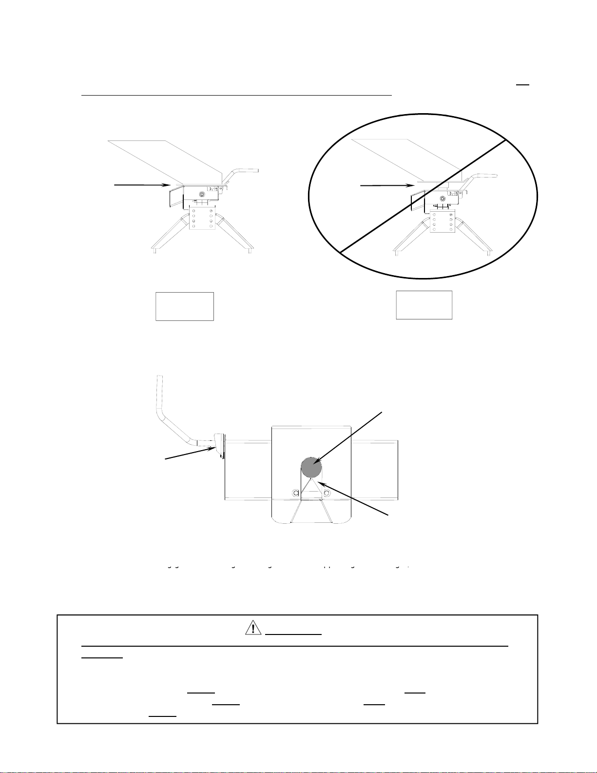
6. Rotate latch for hitch handle toward trailer and free of groove in handle. (Fig. 17 on next page)
7. Pull hitch handle out completely until it latches in open position so that king pin is no longer
securely grasped by hitch jaws (See Fig. 18 on next page). Trailer is now free from hitch and
truck. If handle does not pull out, there is probably pressure against the jaws. To relieve this
pressure, back the truck slightly. Reset truck emergency brake. Then pull hitch handle out
completely until it latches in open position. (See Fig. 18)
30033IN-OCT 28,2008 F PCN11465 ©2005 CEQUENT TOWING PRODUCTS, INC LITHO IN USA 8

Pull Handle all the way out
Latch
Groove in Handle Groove in Handle
Fig. 18
Fig. 17
Latch
Hitch Jaws
8. AFTER MAKING CERTAIN NO ONE IS STANDING BETWEEN TRUCK AND TRAILER OR IN FRONT OF TRUCK,
drive truck slowly away from trailer.
WARNING
Whenever possible, avoid putting body under trailer or between truck and trailer
If you need to place any part of our body under trailer or between truck and trailer:
9. Close hitch jaws by pushing handle forward and up.
(Spring will close jaws.)
•All trailer tires MUST be blocked in front and behind each tire AND
•Trailer landing gear MUST be resting on firm ground AND
•Truck MUST be stationary, in park, with emergency brake on!
10. KEEP WHEEL BLOCKS IN PLACE. This will keep trailer from moving unexpectedl
y
1. Recheck tightness of all hardware every 1000 miles of use.
2. See “Before each trip” section in this manual.
MAINTENANCE:
Cequent Towing Products will replace FREE OF CHARGE any part which proves defective in material or workmanship when presented to any
Cequent Towing Products dealer (consult local telephone directory) or Cequent Towing Products warehouse, or when returned to the factory,
TRANSPORTATION CHARGES PREPAID, at the address below. THIS WARRANTY IS LIMITED TO DEFECTIVE PARTS REPLACEMENT
ONLY. LABOR CHARGES AND/OR DAMAGE INCURRED IN INSTALLATION OR REPLACEMENT AS WELL AS INCIDENTAL AND
CONSEQUENTIAL DAMAGES CONNECTED THEREWITH ARE EXCLUDED.
FIVE YEAR LIMITED WARRANTY
Some states do not allow the exclusion or limitation of incidental or consequential damages, so the above limitation or exclusion may not apply
to you.
Any damage to the 5th Wheel as a result of misuse, abuse, neglect, accident, improper installation, or any use violative of the instruction
furnished by us WILL VOID THE WARRANTY.
This warranty gives you specific legal rights, and you may also have other rights which vary from state to state. In the event of a problem with
warranty service or performance, you may be able to go to a small claims court, a state court, or a federal district court.
30033IN-OCT 28,2008 F PCN11465 ©2005 CEQUENT TOWING PRODUCTS, INC LITHO IN USA 9
Cequent Towing Products, Inc.
47774 Anchor Ct.
Plymouth, MI. 48170

1
3
2
25
22
24
23
46
5
21 20 18
19 7
8
9
10
17 16
10
11
13
12
13
15
27
26
14
ITEM # DESCRIPTION PCS ITEM # DESCRIPTION PCS
22K FIFTH WHEEL
Fig. 19
1 ACTUATING ROD 1 14 SPRING CLIP 8
2 JAW LINKAGE 1 15 1/2-13 BOLT KNURLED 4
3 KLIP RINGS 5 16 SELF TAPPING SCREW 2
4 22K HEAD 1 17 RUBBER BUMPER 2
5 L.H. JAW 1 18 1/2" NUT 1
6 R.H. JAW 1 19 FLAT WASHER - 1/2" 3
7 JAW PIVOT PINS 2 20 LATCH 1
8
KLIP RINGS
4
21
1/2
"-
13 BOLT
1
30033IN-OCT 28,2008 F PCN11465 ©2005 CEQUENT TOWING PRODUCTS, INC LITHO IN USA 10
8
KLIP
RINGS
4
21
1/2
13
BOLT
1
9 PIVOT BEAM 1 22 HANDLE TUBE 1
10 ADJUSTMENT BRACKETS 2 23 COTTER PIN 1
11 PULL PIN SHORT 4 24 SPRING 2
12 1/2" LOCK NUT 4 25 CUSHION GRIP 1
13 LOCK WASHER 1/2" 4 26 PULL PIN LONG 4
27 BASE 1
Table of contents
Other Reese Tools manuals