Reflex ROAD BIKE BASIC User manual

ROAD BIKE BASIC ASSEMBLY GUIDE
NEW UPDATED MANUAL
PLEASE FOLLOW

WARNINGS
KEY BIKE PARTS
BEFORE YOU START
FITTING THE HANDLEBAR
FITTING THE SADDLE
CONTENTS
WARNINGS
IF IN DOUBT - CONSULT A QUALIFIED BICYCLE MECHANIC
OR CALL OUR CUSTOMER HELPLINE ON 0161 727 0139
....................................................page 2
.............................................page 3
.......................................page 4
.............................page 5
....................................page 6
FITING THE FRONT WHEEL
FITTING THE PEDALS
FITTING THE REFLECTORS & BELL
FINAL CHECKS
...........................page 7
.....................................page 10
..............page 11
.............................................page 12
Always check that brakes work before each use - failure to set brakes correctly may result in serious injury or even death.
Ensure all nuts / bolts / screws are securely ghtened and checked before use. Recommended torques (ghtness levels) are
available in the owners manual.
Check bike regularly for signs of damage. Do not use again unl repaired.
Keep your bike in good condion by cleaning off dirt, keeping it well maintained and storing in a dry place.
Always wear a helmet that meets the latest safety standards and make sure you follow the manufaterer’s instrucons.
2
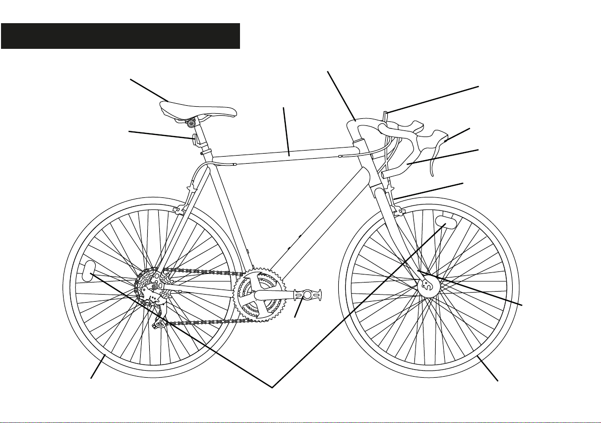
KEY BIKE PARTS
SADDLE
FRAME
BRAKE LEVERS
FRONT REFLECTOR
HANDLEBAR
HANDLEBAR STEM
FRONT BRAKE
& CABLE
FORK
WHEEL REFLECTORS
PEDALS
REAR
REFLECTOR
FRONT WHEEL
BACK WHEEL
3

BEFORE YOU START
CARDBOARD CABLE TIES PLASTIC SAFETY CAPS
(on front wheel &
handlebar stem)
PLASTIC SEPARATION
BAR
(on fork)
Remove all packaging. Take care not to scratch any paintwork.
Please note - The plasc cap / separaon bar may have fallen off in transit if they are not on the bike.
IMPORTANT
Make sure you turn the fork around so that the brakes are facing forwards before you begin building the bike.
We recommend you loosely ghten all bolts to start, then fuly ghten when complete
4

FITTING THE HANDLEBAR
HANDLEBAR
MINIMUM
INSERTION
MARK
BIKE FRAME
AInsert the handlebar into the head tube. Make
sure the minimum insertion mark is not visible
once this is tted. The handlebar must be
inserted beyond this point.
BThe handlebar must be straight. Align this with the fork by
looking downwards at it. Use the allen key to ghten the bolt
on top of the handlebar stem. Do not fully ghten unl the end
as you may need to adjust the height.
ALLEN BOLT
Front of bike
Rear of bike
BRAKES
FORK
TOP VIEW
Front of bike
Rear of bike
5

FITTING THE SADDLE
SADDLE
FRAME
MINIMUM
INSERTION
MARK
A B Using the allen key provided, lock the seat in posion
by turning bolt in a clockwise direcon. Do not fully
ghten unl the end as you may need to adjust the
height.
Insert saddle into frame. Make sure the minumum
insertion mark is not visible once this is tted. The
saddle must be inserted beyond this point
6
FITTING THE FRONT WHEEL
i
ii
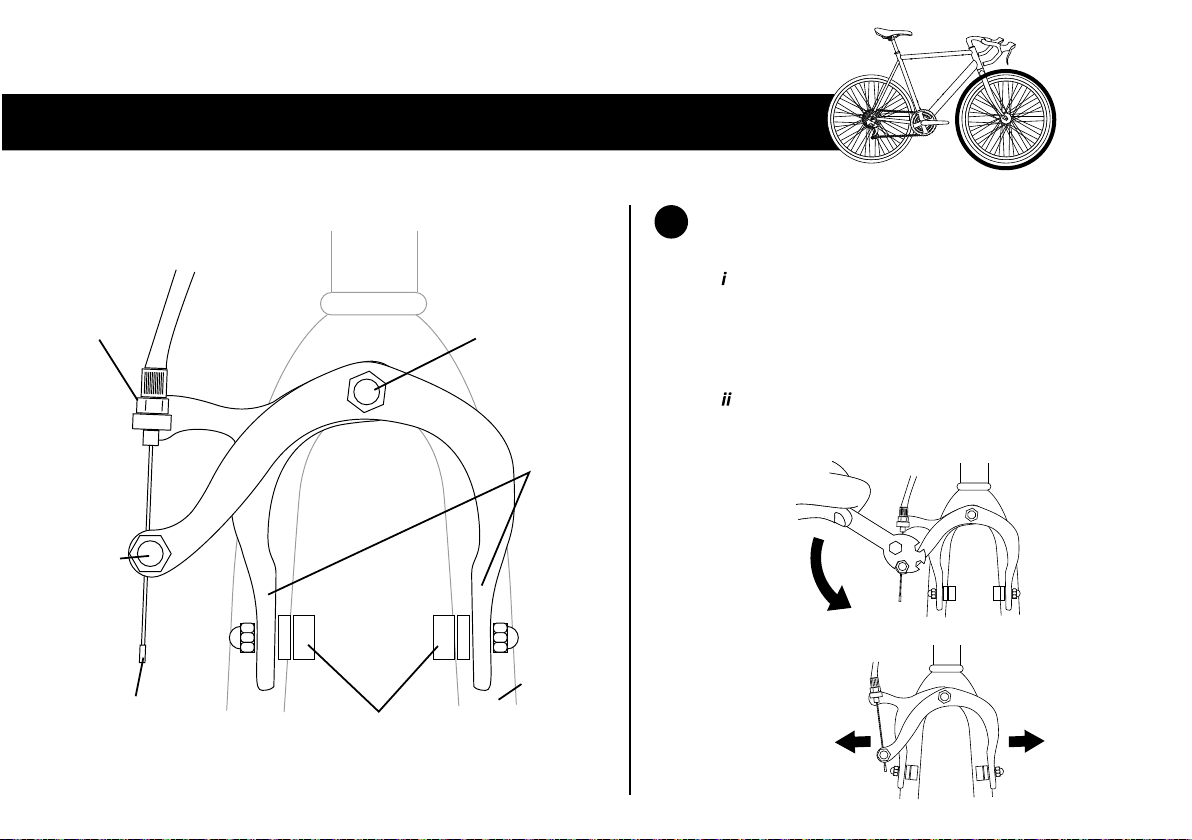
ABefore fing the front wheel, you must open the
brake arms by releasing the brake cable:
Slightly loosen the front brake on the forks
by releasing the brake cable pinch bolt. To
do this turn it anti-clockwise with the
spanner provided as shown.
This will open up the break pads so the
wheel ts through.
BRAKE
ARMS
BRAKE
CABLE
BRAKE
CABLE
TENSION
SCREW
ANCHORING
BOLT
BRAKE
CABLE
PINCH
BOLT
FORK
BRAKE
PADS
7

BTo t the quick release mechanism on the front wheel you will need to join the parts as shown below. The skewer goes
through the axle on front wheel, and the adjusting nut needs attaching loosely by turning clockwise, ensuring the springs
are positioned either side of the axle as shown. Turn the bike upside down and slot wheel onto the fork.
CSecure the wheel in place by holding the quick release lever on one side and tightening the adjusting nut on the other side
until it's nger tight. Close the quick release lever so it's in line with the fork. This must be pushed tightly to the fork - it helps
to wrap your ngers around the fork and lever to squeeze together, it should leave an imprint in the palm of your hand.
QUICK
RELEASE
LEVER
ADJUSTING
NUT
OPEN CLOSED
8
QUICK
RELEASE
LEVER SKEWER
WHEEL AXLE
SPRING
SPRING
ADJUSTING
NUT

DOnce the wheel is in place and tight, turn the bike the right way up. Squeeze the brakes together until there is a 1mm gap
betwen the brake pads and the rim. Both sides should be equal. Whilst holding in place you then need to pull the brake
cable tight, and tighten the brake cable pinch bolt by turning clockwise using the spanner provided as shown.
i ii iii
1mm1mm
CORRECT BRAKE & WHEEL FITTING IS VERY IMPORTANT FOR YOUR SAFETY
IF YOU HAVE ANY PROBLEMS THERE IS MORE INFORMATION IN THE USER MANUAL
SHOULD YOU HAVE ANY DOUBT REGARDING THE BRAKES YOU SHOULD
CHECK WITH A QUALIFIED BICYCLE MECHANIC
FAILURE TO CORRECTLY SET THE BRAKES MAY RESULT IN SERIOUS INJURY
9
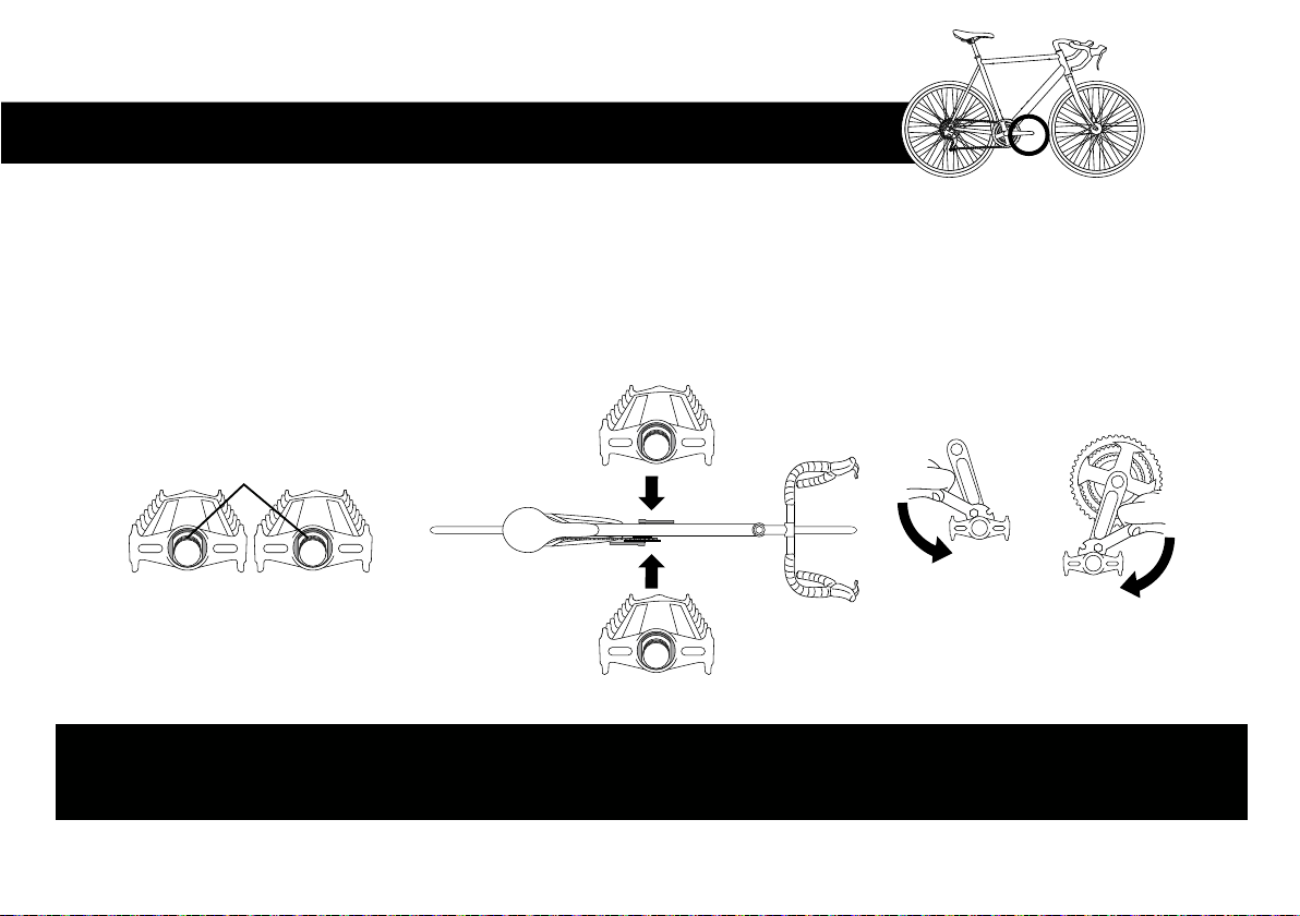
PLEASE MAKE SURE YOU FIT THE CORRECT PEDAL TO THE CORRECT SIDE. FAILURE TO DO SO MAY
RESULT IN CROSS-THREADING, WHICH CAN CAUSE IRREPARABLE DAMAGE NOT COVERED BY WARANTY
FITTING THE PEDALS
SCREW CLOCKWISESCREW ANTI-CLOCKWISE
To fit the pedals correctly, you must posion them the correct way around and screw them on in the right direcon:
Sckers indicate the le and right pedal. If these have dropped off, look at the end of the thread where it is imprinted.
The correct pedal needs to be aached to the matching side of the bike i.e. le pedal to le side and right pedal to right side.
IMPORTANT! Pedals need screwing in opposite direcons so they don’t fall off in use.
Le pedal is screwed in an-clockwise / Right pedal is screwed in clockwise. Tighten pedals with spanner provided.
i
i
ii
iii
ii iii
THREADS
L R
LEFT RIGHT
L
R
10
Table of contents
Other Reflex Bicycle manuals


