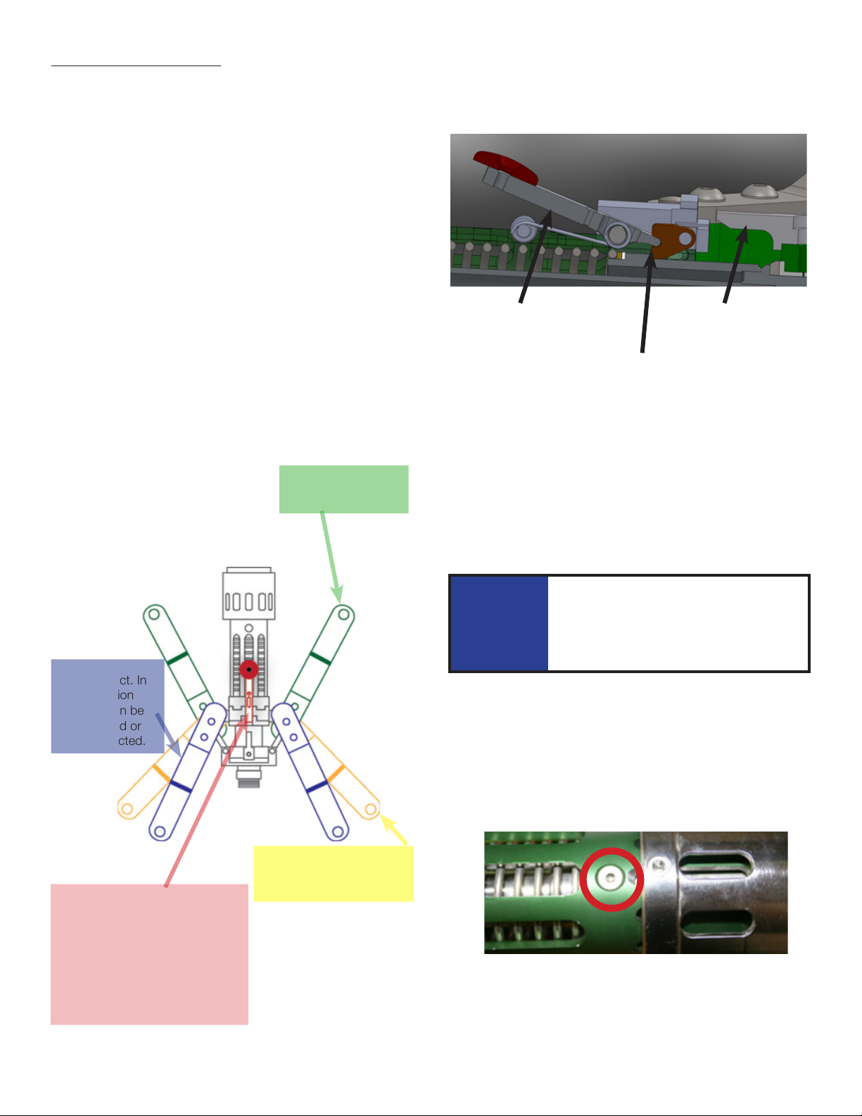
Replacement of Poppet Assembly and Seat/
Seal Assembly
If the Nozzle is leaking only while connected to the receptacle you
may replace the Seat/Seal Assembly (p/n 14255) without replacing
the Poppet assembly (p/n 13960). The current poppet assembly
can be used with the new Seat/Seal Assembly if the nozzle does
not leak when disconnected. If the nozzle experiences any leakage
while disconnected, both the Poppet and Seat/Seal Assemblies
need to be replaced.
Parts Needed
(Parts sold separately)
Poppet Assembly
p/n 13960
Receptacle Interface Seal
p/n 14591
Seat Assembly
p/n 14255
(Contains Receptacle Interface Seal) Socket Tool
p/n T-2961
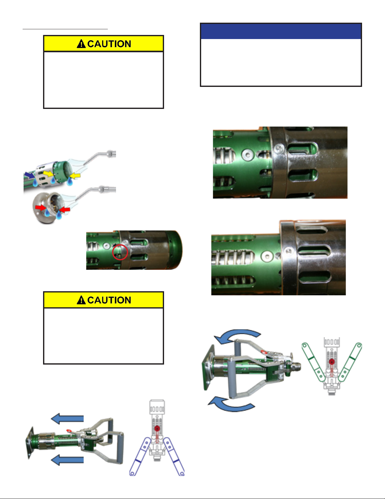
NOTICE
If purchased separately, the receptacle interface seal must
be assembled with the brass retainer according to Macro
Technologies instructions using the proper seal repair tool
kit: p/n 14590.
Tools Needed: In addition to the above parts, you will also need
an open ended 1-18” wrench a Torque Wrench (recommended) or
Socket Wrench with a 1” socket attachment and a vise.
Open end side of seal
facing retainer flange
Closed end side of seal
facing retainer threads
NOTICE
Make sure that the removal tool is all the way pushed into
the mating Seat/Seal Assembly hex or you could possibly
strip the retainer. Use care when removing the retainer.
If not removed carefully, the poppet may pop out of the
Nozzle, potentially causing personal injury and damage
the parts.
1. Remove all items from their shipment packaging taking care in
handling them so that they are not damaged. Carefully inspect
parts to ensure that all sealing surfaces are clean, free of dirt
and contamination.
2. Place the wrench in the vise and secure the end of the Nozzle
as shown to the left.
3. Align Socket tool (T-2961) with Seat/Seal Assembly hex
and place 1” socket wrench onto Socket tool and turn
counterclockwise to remove the Seat/Seal Assembly. Once
the Seat/Seal Assembly is fully unscrewed, the spring behind
the poppet Assembly will push the Poppet Assembly out of the
Nozzle.
4. Remove the old Poppet Assembly and Seat/Seal retainer. If
the Nozzle is only leaking while connected, the current poppet
Assembly does not need to be replaced. However, it should
still be carefully inspected to ensure that all sealing surfaces
are clean and undamaged.
Inspect Seat/Seal Assembly (p/n 14255) to confirm that
receptacle interface seal has been positioned correctly. The
seal should be positioned with the open side facing the retainer
flange. The closed side should be facing towards the retainer
threads.
If purchased separately, the Receptacle Interface Seal must be
assembled with the brass retainer according to Macro Technologies
instructions using the proper seal repair tool kit: p/n 14590. See
replacement of Interface seal if you are repairing the Receptacle
Interface Seal separately.
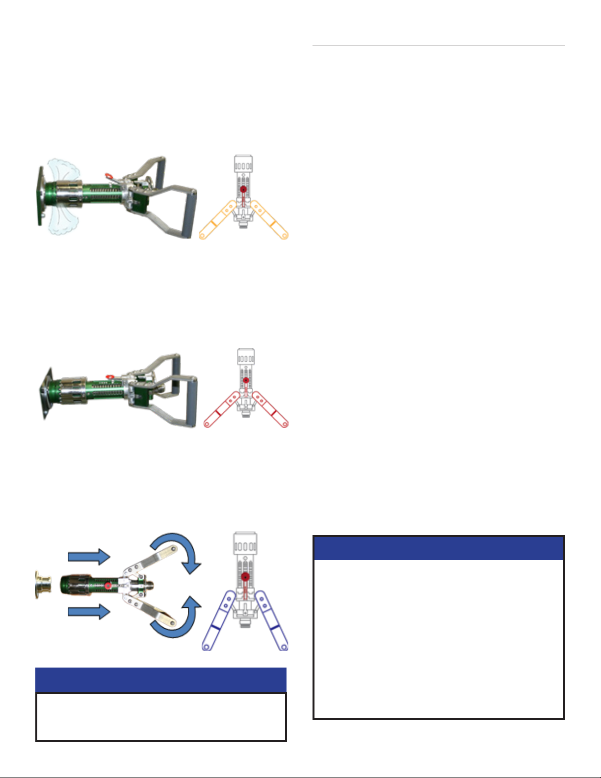
5. Use the Socket Tool (p/n T-2961) to carefully align Poppet
Assembly and Seat/Seal Assembly.
6. Place the Poppet assembly, Seat/Seal Assembly, and Socket
Tool on the spring with the tool facing away from the nozzle.
Use of Socket tool T-2961 is important and critical in
order to properly guide all components into place. Failure
to properly guide components into place with Socket
Tool T2961 may result in misalignment on critical sealing
surfaces.
If not aligned correctly, the seal on the poppet Assembly
and/or the seal of the Seat/Seal Assembly may become
damaged.
NOTICE
7. Push the Poppet assembly down by hand while threading the
Seat/Seal Assembly clockwise onto the Nozzle. Once you feel
the assembly threading into the Nozzle, you can remove the
pressure.
If assembled backwards, the seal will fail
prematurely.
7