manuals.online logo
Brands
  1. Home
  2. •
  3. Brands
  4. •
  5. Rego
  6. •
  7. Industrial Equipment
  8. •
  9. Rego TA7894P User manual

Rego TA7894P User manual

WARNING: Installation, disas-
sembly, repair and maintenance
MUST be performed only by quali-
ed personnel. All gas MUST be
evacuated from the system before starting repairs.
Installation, usage and maintenance of this product must be in compli-
ance with all RegO®instructions as well as requirements and provisions
of NFPA #54, NFPA #58, DOT, ANSI, all applicable federal, state, provincial
and local standards, codes, regulations and laws.
Inspection and maintenance on a periodic basis is essential.
Be sure all instructions are read and understood before installation, opera-
tion and maintenance. These instructions must be passed along to the
end user of the product.
RegO Rail Tank Car equipment is AAR approved. If repaired, the continued
validity of the AAR approval is contingent upon proper inspection to de-
termine what needs to be repaired; proper repair using RegO OEM parts
and procedures, proper testing for leakage and performance following
repairs and installation.
ECI EXPRESSLY DISCLAIMS ANY AND ALL LIABILITY – UNDER ANY
THEORY, WHETHER CONTRACT, WARRANTY, TORT OR OTHERWISE – RE-
LATING IN ANY MANNER TO ANY RAIL TANK CAR EQUIPMENT REPAIRED
USING ANY PRODUCTS NOT MANUFACTURED BY ECI.
USE OF ANY PRODUCTS NOT MANUFACTURED BY ECI TO REPAIR ANY
RAIL TANK CAR EQUIPMENT WILL INVALIDATE ANY AND ALL WAR-
RANTIES OF THE RAIL TANK CAR EQUIPMENT, WHETHER EXPRESS
OR IMPLIED.
CAUTION: Contact or inhalation of liquid propane, ammonia and their va-
pors can cause serious injury or death! NH3 and LP-Gas must be released
outdoors in air currents that will insure dispersion to prevent exposure to
people and livestock. LP-Gas must be kept far enough from any open ame
or other source of ignition to prevent re or explosion! LP-Gas is heavier
than air and may not disperse or evaporate rapidly if released in still air.
TA7894-50 Rebuild Kit For
TA7894P Tank Car Valves
Seal Housing
Wiper O-Ring*
Pressure Seal Rings (2)*
Jam Ring*
Washer*
Seal Housing Gasket*
Spring*
Cap Screw (4)
Bonnet**
Body Gasket*
Seat Disc Retainer
Seat Disc*
Seat Disc Retainer Nut*
Stem Holder
Stem**
Stem Retainer (2)
Body
Figure 1-TA7894P Figure 2-Seal Housing Assembly
* All components included in the TA7894-50 kit are recommended for valve rebuild.
** Must be ordered separately from RegO®.
1- 5/16"
Wrench
Flats
stake here




Disassembly and Rebuild Procedure
CAUTION: READ THROUGHALL OF THESE INSTRUCTIONS, INCLUD-
ING THE NOTICE AND WARNINGS ON THE BACK OF THIS SHEET,
BEFORE BEGINNING ANY DISASSEMBLY OR REPAIR.
NOTE: Repairs must be performed in a clean area. Hands, clothing, tools
and work area must be completely free of oil, grease and foreign matter to
prevent contamination of component parts and valves.
A. Disassembly
CAUTION: EVACUATE ALL GAS FROM THE SYSTEM BEFORE ANY
DISASSEMBLY OR REPAIR.
1. Remove 2" plug from valve outlet.
2. Turn handwheel counterclockwise as far as it will go to release any
gas remaining in the container.
CAUTION: Do not apply force after valve is fully open.
3. Removeangebyremovingthe(8)angecapscrews.Setallaside.
4. Removeanddiscardtheangegasket.
5. Using a 13/16" wrench, remove four cap screws from bonnet and set
aside for reassembly. Carefully remove bonnet assembly from valve
body. Set seat disc retainer aside.
6. Remove body gasket and discard.
7. Clamp the square section of bonnet in a vise.
8. Remove handwheel locknut with a small wrench to allow removal of
washer, information disc and handwheel. Set items aside.
Figure 4-Screw Tightening Sequence
Apply minimum
300±25 in-lbs (25±2
ft-lbs) torque using a
tightening sequence
of alternating bolts in
a crisscross pattern.








Apply minimum
540±25 in-lbs (45±2
ft-lbs) torque using a
tightening sequence
of alternating bolts in
a crisscross pattern.
Bonnet Flange Outlet Flange
Figure 3-Seat Disc and Retainer Assembly
Locknut
Washer
Handwheel
Information Disc
Flange Gasket*
Flange Cap Screw (8)
Flange
Plug
10
REGO
YEAR
WARRANTY
Stem Sealing
Area
Handwheel Resting Location
Printed in USA REV P 14-1219-0281
Instruction Sheet TA7894-300
9. Usinga1-3/8"wrenchwithahandleofsu󰀩cientlengthtodevelopa
minimum of 1000 in-lbs (83 ft-lbs) torque, carefully remove seal housing
from bonnet.
CAUTION:Donotmarnishofstem.
10. Remove and discard pressure seal rings, jam ring and wiper o-ring from
seal housing.
11. Using a small wrench on the square section of the stem, unscrew stem
down and out through the bottom of bonnet by turning clockwise (as
viewed from top).
CAUTION: Stem inspection required.
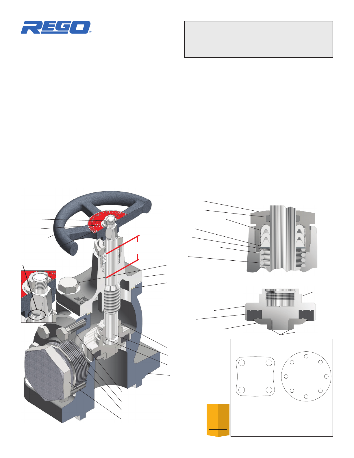
12.Inspectthestemcloselyfordenitesignsofwear,nicksorscratches,
inthesealingarea,seegure1,StemSealingArea.Ifanymechanical
cleaning is needed, use emery cloth or paper (500-1000 grit) and polish
stem sealing area using a circular motion. Use the same criteria for the
packingnutwipero-ringareaofthestem,seegure2,SealHousing
Assembly. If any permanent damage is found discard the stem and
replace with a new stem.
CAUTION: Raised or sharp edges on the stem can damage and expand
the packing seals when pressing onto the stem.
13. Inspect the handwheel resting location where the stem changes from
square to round, see gure 1 Handwheel Resting Location. Remove
anyraisededgesorburrsusinganeleandemerycloththatare
higher than the stem diameter. Using an old seal, press seal on and
o󰀨thisareatodetermineifanyresistanceisfelt.Resistancemay
require additonal clean up.
14. Remove and discard seal housing gasket, washer, and spring from bon-
net.
NOTE: Inspect stem** threads and mating threads in bonnet**. If any threads
show denite wear, discard part and install a new one.
15. Remove seat disc retainer nut by using 1-5/16" wrench to secure retainer
and another wrench to remove nut.
16. Remove and discard seat disc.
B. Reassembly
1. Install new seat disc into seat disc retainer by pressing into the recess
ofseatdiscretainerasshowningure3.
2. Apply Loctite 271®threadlockingcompoundtotherstthreethreads
of seat disc retainer.
CAUTION: Do not allow Loctite to contact seat disc.
3. Thread on disc retaining nut and tighten with a wrench to 240-270 in-lbs
(20-23 ft-lbs) torque. Stake nut in two places at retainer threads to prevent
loosening. See Figure 3. Set assembly aside.
4. Apply non-detergent grease liberally to threads of stem.
5. Screw the stem clockwise (as viewed from seat disc) into the bottom of
bonnetwithgreatcaretoavoiddamagingstemnish.
6. Install new seal housing gasket, new spring, new washer and jam ring
over stem and into bonnet.
7. Install new wiper o-ring in groove of seal housing.
8. Applyathinlmofnon-detergentgreasetothepressuresealringsand
carefully insert one at a time into the full depth of the seal housing.
9. Apply 1/8" stripe Loctite 271®thread locking compound across threads
in three places equally spaced around seal housing.
10. Place seal housing carefully over the stem to avoid damaging the edges
of seal rings and thread into bonnet. Tighten to 800 in-lbs (67 ft-lbs)
torque, using a 1-3/8" wrench with a handle of appropriate length.
11. Apply non-detergent grease to each side of new body gasket and install
into body.
CAUTION: Using the handwheel, verify the stem is in the full open (valve
back seated) position to prevent seat disc from being forced against seat
when bonnet is assembled to valve body.
12. Place bonnet over body and align holes for cap screws.
13. Install (4) cap screws, hand tight.
14. Using appropriate wrench, tighten bonnet cap screws to 540 in-lbs (45
ft-lbs) torque using a crisscross tightening sequence. See Figure 4.
15. Place handwheel and information disc on stem, secure with washer and
locknutandtightenrmlywithasmallwrench.
16. Applynon-detergentgreasetoeachsideofangegaskettheninstallin
body.
17. Reinstallangetooutletandhandtighten(8)angecapscrews.
18. Torque eachangecap screw300in-lbs (25ft-lbs)minimumusing a
crisscrosstighteningsequence.Seegure4.
19. Turn handwheel to closed position for Bench Test.
Bench Test
1. Torque handwheel to 400 in-lbs (33 ft-lbs). Verify outlet is open.
2. Pressurize valve to 300-500 psi (through the inlet connection) and check
valve for leakage, when looking into the outlet port, by applying a high
quality leak detection solution around seat area and seat cavity. Observe
for one minute to detect leaks.
3. Release 300-500 psi, apply 15-20 psi and look for any leakage as above.
4. Install outlet plug, again apply 300-500 psi and slowly open valve by
turning handwheel 1/4 turn incrementally. Check valve for leakage by
applying a high quality leak detection solution around stem, seal housing
and bonnet joint. Continue to rotate handwheel 1/4 turn incrementally
until valve is fully open (not back seated). Observe for one minute to
detect leaks.
CAUTION: Wrenches must never be used to operate valves equipped with
handwheels designed for hand operation.

This manual suits for next models

1

Other Rego Industrial Equipment manuals

Rego A8434F-50 User manual

Rego

Rego A8434F-50 User manual

Rego TA7894-50 User manual

Rego

Rego TA7894-50 User manual

Rego Macro CryoMac 3 User manual

Rego

Rego Macro CryoMac 3 User manual

Popular Industrial Equipment manuals by other brands

ABB HT611546 Operation manual

ABB

ABB HT611546 Operation manual

Eckold KRAFTFORMER KF 800 operating instructions

Eckold

Eckold KRAFTFORMER KF 800 operating instructions

Napa Carlyle Tools 791-6005A operating manual

Napa

Napa Carlyle Tools 791-6005A operating manual

Greenbridge PC2000 Operation manual

Greenbridge

Greenbridge PC2000 Operation manual

ABB HT604570 Operation manual

ABB

ABB HT604570 Operation manual

Wöhner CrossBoard 11 500 quick start guide

Wöhner

Wöhner CrossBoard 11 500 quick start guide

ABB EVLunic Series installation manual

ABB

ABB EVLunic Series installation manual

Danfoss AFD operating guide

Danfoss

Danfoss AFD operating guide

CARLO GAVAZZI SCTL55 instruction manual

CARLO GAVAZZI

CARLO GAVAZZI SCTL55 instruction manual

Pilous ARG 260 CF-NC automat instruction manual

Pilous

Pilous ARG 260 CF-NC automat instruction manual

Facom W.415WBA instruction manual

Facom

Facom W.415WBA instruction manual

Eaton RMQ-M1C-ASI Instruction leaflet

Eaton

Eaton RMQ-M1C-ASI Instruction leaflet

Swagelok MS-PSR-110 manual

Swagelok

Swagelok MS-PSR-110 manual

GSI Group SCR Series instruction manual

GSI Group

GSI Group SCR Series instruction manual

ABB CC1600-SC55 quick start guide

ABB

ABB CC1600-SC55 quick start guide

HyQuest Solutions HailSens IoT user manual

HyQuest Solutions

HyQuest Solutions HailSens IoT user manual

UNITED TC250 Operation & maintenance manual

UNITED

UNITED TC250 Operation & maintenance manual

Baileigh HARE&FORBES TN-300 Operator's manual

Baileigh

Baileigh HARE&FORBES TN-300 Operator's manual

manuals.online logo
manuals.online logoBrands
  • About & Mission
  • Contact us
  • Privacy Policy
  • Terms and Conditions

Copyright 2025 Manuals.Online. All Rights Reserved.