REGULA 7517A User manual

HARDWARE AND SOFTWARE SYSTEM FOR FORENSIC
EXAMINATION OF FIREARMS AND AMMUNITION SERIAL
NUMBERS REGULA 7517.
MAGNETO-OPTICAL DEVICE REGULA 7517A
USER’S GUIDE
Certied Quality
Management System
Regula Ltd.
2017


CONTENTS
ABBREVIATIONS .....................................................4
INTRODUCTION .....................................................5
1 DESCRIPTION AND OPERATION .........................................6
1.1 Device Description and Operation ....................................6
1.1.1 Device Function .............................................6
1.1.2 Technical Specications .......................................6
1.1.3 Delivery Set ...............................................8
1.1.4 Conguration and Operation ....................................9
1.1.5 Means of Measurement, Tools and Accessories ......................10
1.1.6 Marking .................................................11
1.1.7 Packaging ................................................11
1.2 Description and Operation of Device Components ........................11
1.2.1 USB Device for Magneto-Optical Visualization (MOV USB Device)..........11
1.2.2 Magnetic Copying Accessories Set (MCAS) .........................13
1.2.3 Personal Computer (PC) ......................................14
1.2.4 Software.................................................15
1.2.5 Spare Parts and Repair Kit (SPRK) ...............................15
2 INTENDED USE ...................................................16
2.1 Device Intended Use ............................................16
2.1.1 Safety measures and operating limitations .........................16
2.1.2 Preparing the device for operation ...............................16
2.2 Intended Use of Device Components .................................17
2.2.1 MOV USB device ...........................................17
2.2.2 Magnetic Copying Accessories Set ...............................19
3 MAINTENANCE OF THE DEVICE COMPONENTS ..............................27
3.1 MOV USB Device ...............................................27
3.2 Magnetic Copying Accessories Set...................................27
4 ROUTINE REPAIRS .................................................28
4.1 General Instructions ............................................28
4.2 Repair Instructions .............................................28
5 STORAGE .......................................................30
6 TRANSPORTATION .................................................30
7 RECYCLING ......................................................30
8 MANUFACTURER’S WARRANTY .........................................30
9 ACCEPTANCE CERTIFICATE ...........................................31
10 SALE CERTIFICATE ................................................31

ABBREVIATIONS
MCAS — magnetic copying accessories set
MOI — magneto-optical image
MOV — magneto-optical visualization
MOV USB device — USB device for magneto-optical visualization
OMB — optic-mechanical block
MT — magnetic tape
SPRK — spare parts and repair kit
CMS — combination magnetic scanner

5
INTRODUCTION
The User’s Guide is the main operational document to the magneto-optical device
Regula 7517A (hereinafter referred to as the “device”). The device is a part of the hardware
and software system for forensic examination of rearms and ammunition serial numbers
Regula 7517. As a part of the system the device is used together with the eddy-current
magnetographing device Regula 7517B and magnetizing equipment Regula 7517C.
The User’s Guide contains information concerning device and its components design,
principles of operation and specications. The Guide also provides instructions on the correct
and safe use of the device (intended use, maintenance, routine repairs, storage and
transportation) and on its technical condition evaluation when deciding whether it is necessary
to send the system for repairs.
Description of the device software is given in a separate document.
Personnel operating the device are required to:
zhave higher or specialized technical education,
zpass special training and get clearance to perform expert examination in the eld of
trace evidence,
zbe an OS Windows user,
zstudy techniques of authenticity verication of rearms and ammunition serial numbers
and the User’s Guide,
zpass practical training on the use of equipment supplied,
zpass training on safety measures observed when working with the system.
ATTENTION!
USB devices do not have dangerous voltage as they are powered by
a secondary power supply source — a PC USB-bus with nominal voltage 5 V.
However, the mains power source and PC peripherals (supplied optionally)
can have life hazardous nominal voltage ~ 220 V 50 Hz. To avoid electric
shock personnel are obliged to strictly observe the safety measures.
ThedeviceisclassiedasClassIEquipment(IEC60950–1)withregardto
protection against electric shock.
Themagneticcopyingaccessorysetcontainsinammableliquid(alcohol).
To ensure device proper operation it is strongly recommended not to
change software settings. The system should be operated, maintained,
repaired, stored and transported in conformity with paragraphs 2–6 of
this User’s Guide. Violation of these requirements will result in the loss of
the manufacturer’s warranty.

6
DESCRIPTION AND OPERATION
Device Description and Operation
Device Function
The device is intended for forensic examination of rearms and ammunition serial numbers
with the following purposes:
zserial numbers authenticity verication,
zrecovery of initial numbers in case of any damages in their relief (corrosion, scale, wear, etc.),
zrecovery of initial numbers in case of their removal,
zgeneral trace evidence examinations and non-destructive testing of relief and stresses
in the surface layer of metal objects.
Regula 7517A is a set of hardware and software products enabling visualization (video
imaging) of relief and structural inhomogeneity of metal surface with magnetic properties
(traces of mechanical processing, inclusion of non-ferromagnetic materials, surface aws
of welding seams), without removing the lacquer-and-paint coating (if applicable) by methods
of magneto-optical visualization. A PC is used for capturing, collecting, processing, transferring
and displaying information.
Area of application
The device is intended for use by forensic laboratories, law enforcement agencies, judicial
authorities, customs and insurance companies. Regula 7517A can be used for express
inspection (e.g. at customs or by highway patrol), as well as for advanced forensic examination
of rearms serial numbers in laboratory conditions due to the fact that the device provides
high-quality results, visual evidence and uses non-destructive magneto-optical methods.
In case any changes in serial numbers are detected, further investigations can be carried out
using a special set of peripheral hardware tools (supplied optionally).
Storage and operation conditions
The system is to be used indoors.
Climatic conditions:
air temperature +10˚С … +35 ˚C
relative air humidity up to 80 % at temperature of +25 °C
atmospheric pressure from 84 to 107 KPa (from 630 to 800 mm
mercury)
Operating temperature on the data carrier surface during magnetic copying: -20 ˚С…+50 ˚С.
Operating temperature on the surface of the combination magnetic scanner during magnetic
copying: -20 ˚С…+50 ˚С.
Climatic conditions of storage (see paragraph 5).
Climatic conditions of transportation (see paragraph 6).
Avoid hitting and vibrations during device transportation and operation.
TechnicalSpecications
Device technical specications are given in the description of its components
(see paragraphs 1.2.1–1.2.3).
In working conditions device nonstop operation with maintained performance lasts for up
to 8 hours.
Warm-up time — maximum 3 min.
Power supply
Autonomous
power supply PC battery
Mains power supply External PC power supply source, converting AC voltage of 110–240 V,
frequency 50–60 Hz into DC voltage of PC power supply.
External PC power supply source, converting DC voltage of the vehicle
on-board system (nominal value — 12/24/48 V) into DC voltage of PC
power supply.
1
1.1
1.1.1
1.1.2

7
Power consumption
USB device for
magneto-optical visualization not more than 2,5 W
Reliability
Time to failure not less than 10 000 hours
Mean lifetime not more than 5 years
Operation warranty period 12 months from the date the device is delivered to
the customer
Storage warranty period 12 months
Dimensions
In transportation packaging not more than 350×280×220 mm
In working position (open case) not more than 240×110×110 mm
Weight in transportation packaging
Gross weight not more than 4 kg
Net weight not more than 3,2 kg

8
Delivery Set
The device delivery set is given in Table 1.
Table1
Components Quantity Packing Figure№ Marking
USB device for magneto-optical
visualization 1
box 3
Regula 7517A
serial #,
year of
production
USB cable to connect to the PC 1
**Laptop 12’’ 1
**External PC power supply source 1
Magnetic copying accessories set box 8–10
Combination magnetic scanner-demagnetizer
with the set of changeable concentrators:
rotary 15 mm
1case 8
1case
rotary 21 mm 1bag
at 11 mm 1case
Compact magnetic scanner 11 mm 1bag
Magnetic tape cartridges 2case 6
Magnetic tape reserve (magnetic tape strip,
250 mm) 10 case
Magnetic clamps for magnetic tape 2case
Container for alcohol (10 g) 1bag 7d
Brush 1bag —
Marker 1bag —
Case for accessories 1box 1b
Bag for accessories 1box 1b
**Peripheral examination tools Regula 7516 body-case Regula 7516
Software
**PC drivers and utilities +/-
CD folder — —
CD 1
**OS Windows XP +/- CD 2
**MS Ofce +/- CD 3
Special software for managing USB devices,
for capturing, processing and stitching images
NUCA (EYER) 1 CD 4
Driver for the USB device for magneto-
optical visualization 1 CD 4
Software settings les 1 CD 4
Graphic les (.cdr, dwg) of paper cartridges
for threading plastic magnetic tape 2 CD 4
Operational documents — —
Passport 1
Regula 7517A user’s guide 1
**User’s guide to eddy-current scanners
Regula 7515
+/-
** User’s guide to peripheral examination
tools Regula 7516
+/-
User’s guide to NUCA (EYER) software 1
**PC user’s guide +/-
Warranty card 1
Spare parts and repair kit — —
Magnetic tape cutter + metal magnetic
tape reserve (10 m roll) 1bag
1’’ plastic magnetic tape reserve (10 m roll) 1bag
½’’ plastic magnetic tape reserve
(5 m roll) 1bag
Paper cartridges intended for threading ½’’
plastic magnetic tape 1bag
1.1.3

9
Components Quantity Packing Figure№ Marking
Test-object 1bag 1b, 2 —
Sleeve gaskets of the combination
magnetic scanner 2bag —
Polyethylene bag 1box —
Transportation packaging 1 — —
Regula 7517A
serial #,
year of
production
** — supplied optionally.
CongurationandOperation
Regula 7517A is a set of hardware components and software products. The device allows
examining objects using different methods.
Examination starts with magnetic copying (making a magnetogram = magnetic copy) of
the ferromagnetic object surface. The magnetic copying accessories set (MCAS) contains
various kinds of magnetic scanners which locally magnetize the object, excite its magnetic
stray elds and copy them to the intermediate exible magnetic carrier (magnetic tape) without
removing the lacquer–and-paint coating. The eddy-current scanner (supplied optionally) is
used for investigating internal stresses in ferromagnetic objects and for examining the surface
of aluminum objects.
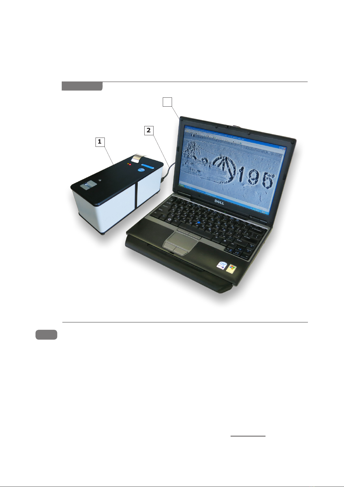
The magnetogram is loaded into the USB device for magneto-optical visualization
(MOV USB device) where information about object’s surface layer is scanned. The MOV USB
device combines two functional components: optic-mechanical block and block of electronics.
The optic-mechanical block (OMB) contains a magneto-optical visualizer which converts
magnetic stray elds of a magnetic copy into an image and a special tape drive mechanism
which moves the magnetic copy relative to the visualizer.
A magnetic copy is loaded into the tape drive where it is automatically detected and
introduced into the tape drive tract. Then it is scanned step-by-step by a sensor designed
on the basis of a magneto-optical crystal. Magneto-optical visualization of magnetograms of
the examined object is based on Faraday magneto-optical effect which occurs in crystalline
lms of Bi-containing ferrite garnets.
Light distribution obtained as a result of visualization is received by the sensitive element
of the video camera and is converted into a digital TV signal which is further processed and
examined with the help of PC software.
Step-by-step input of images into a PC allows making automatic panoramic stitching of a
digital image from several sub-shots.
The block of electronics manages OMB resources (electric drive, inductor, illuminator,
video camera and indicators).
The PC operates the MOV USB device via special software. The PC displays newly obtained
and stored examination data which are processed, examined and documented.
Peripherals (supplied optionally) extend examination possibilities of the device by applying
additional methods and means of investigation.
The device operates together with the following peripherals:
zUSB device for optical input,
zmagnetic powder visualization device,
zeddy-current probe,
zelectrochemical etching device.
Basic functions of NUCA (EYER) software:
zoperating USB devices,
zinput and processing of images,
zautomatic program correction and panoramic stitching of MOV frames,
zimage scaling and rotation,
zcomparison of images,
zmeasurements of linear and angular sizes,
zsaving and printing of image les as illustrations to the photo charts.
Table1(continued)
1.1.4

10
A set of operational documents contains data on design, principles of operation,
properties of the device and its components. It also contains instructions on correct and safe
device operation and evaluation of its technical condition when deciding whether it is necessary
to send it for repairs.
The device is designed as a compact unit for desktop use. The general view of the device
is given in Figure 1.
Figure1
1 — MOV USB device, 2 — USB-cable, 3 — PC (laptop).
Means of Measurement, Tools and Accessories
The device belongs to indicating (not measuring) equipment. Therefore control of device
operation is carried out using test-objects, simulating several known methods of number
alteration (cold calking, sealing with fusible metals, dot welding and pressing-in fragments).
See paragraph 2.2.1.2 for the details of the device operational check-up using the test-object.
Test-objectspecications
The test-object (see Figure 2) imitates an examined object. It is a plate (unkilled sheet
steel) with the thickness of 0,8–0,9 mm bearing “291634” original number applied by mechanic
pressing (cold stamping). The original number details: manual stamping with the use of “font
No.6” stamping set and a hammer on a massive anvil. The depth of digit relief is about 0,3–
0,4 mm.
Three digits of the original number were modied: “9” to “0”, “6” to “9” and “4” to “5”.
Thus, the altered number appears as “201935” (altered digits are underlined).
Digit “9” of the original number was altered manually using cold calking of one element
(crosspiece) of digit “9” with the help of bench tools. Then digit “0” was stamped over
the remaining contour of digit “9”.
1.1.5
1
2
3

11
Photo of the test-object examined surface
Figure 2
1.1.7
1.1.6
Alterations of digit “6”. The original number fragment bearing digit “6” was dismantled (cut
out), rotated by 180°, pressed in (so that digit “6” transformed into digit “9”) and then was
xed in the plate frame by spot welding.
Digit “4” of the original number was modied by means of sealing the digit relief with
soft metal (tin) and then stamping a new digit “5” over the built-up area.
After the original digits were altered, the following operations were performed on the test-
object: grinding, spackling, dressing, priming, two-layer spray-on painting with aerosol motor
enamel using the technique of cold drying in accordance with the repaired coating type.
Marking
Device marking is performed in the form of a label on the rear side of the PC panel.
The marking label provides the following information:
zmanufacturer’s name and/or trade mark,
zmanufacturer’s model identication,
zdevice serial number in compliance with the numbering system of the manufacturer,
zdate of manufacturing (year and month),
zrated voltage, V,
zrated current, A,
znominal frequency, Hz,
znational certication mark.
Device sealing is made with the help of destructible security labels applied on the OMB body
and on the device chassis. Damage to the security label causes a loss of warranty.
The SPRK is labeled on the repair kit’s bag.
Packaging
The device is transported and stored in a special cardboard box of the delivery set. Device
components are arranged in conformity with Table 1.
Description and Operation of Device Components
USB Device for Magneto-Optical Visualization (MOV USB Device)
Functions
zMagneto-optical visualization of a physical copy from MT.
zTransforming a visualized image into a digital TV signal.
zChanging frames due to step-by-step movement of MT in the tape drive mechanism
with further automatic stitching.
zIndicating current system status.
1.2
1.2.1

12
TechnicalSpecications
Material of the examined object ferromagnetic
MT width 25,4 and 12,6 mm
MT maximum length unlimited
MT examined width not less than 20 mm
Physical size of an image dot (frame format 1280×1024) 16 μm
Acceptable thickness
of nonmagnetic coating
(see Figures 7–8):
for detailed examination (spatial resolution 80 μm) not more than
0,1 mm
for general research (spatial resolution 400 μm) not more than
0,5 mm
Acceptable thickness of the removed surface layer of metal not more than
1,0 mm
Approximate time of input of a magnetic copy of the number platform 15 sec
OS Windows XP or later
Format of image les BMP, PCX, GIF,
JPG
PC monitor size >12”
Approximate size of an image le of the number platform (75 % JPG, 640×512) 1,8 Mb
Operation time:
in autonomous mode (depends on a PC type), usually not more than
3 hours
when powered by AC mains not less than
8 hours
Consumed electric capacity on the USB bus not more than
2,5 W
Design
The MOV USB device is designed as a desktop unit. It is sealed and covered with protective
casing.
Figure3
1 — tape drive (place to insert MT),
2 — pressing roller block (for manual
extraction of MT),
3 — status indicators of the MOV
USB device,
4 — bunker (place to extract MT).
MOV USB device
3
42
1

13
1.2.2
State indicators of the MOV USB device:
— “device is passive” (special software is not operating with the device),
— “device is active” (special software is operating with the device),
— “MT in the bunker” (insertion or extraction of MT),
— “MT in the tract” (stitching is in process).
Algorithm of MOV USB device operation
zSwitching the PC on, loading the OS, initializing software. Automatic check-up of
the state / pre-installation of OMB equipment.
zMT is manually inserted into the OMB buffer. Then MT is captured by the magnetic tape
drive and moved to MOV working zone.
zStep-by-step movement of MT is followed by panoramic stitching of MOV images.
zThe quality of stitching and its informative value is controlled.
zMT extraction: direct or reverse rotation depending on the length of the inserted MT
strip. Manual extraction of MT from the OMB buffer. The device switches to a stand-by
mode.
zThe equipment automatically switches to a stand-by mode when the “Stop” mode lasts
longer than ≈ 5 minutes. The stand-by mode is switched off as soon as a new command
is received.
Magnetic Copying Accessories Set (MCAS)
Functions
zCreating a physical copy (recording information to intermediate exible magnetic carrier —
magnetic tape) of magnetic stray elds distribution over the object surface. The copy reects
relief and structural inhomogeneity of the material. Permanent magnets of the combination
magnetic scanner (CMS) concentrators serve as sources of magnetic stray elds excitation.
zDemagnetizing magnetic tapes for further use.
zArranging, marking, storing and carrying the operating reserve of MT and recorded
magnetic copies.
zService functions while performing magnetic copying.
TechnicalSpecications
Dimensions of physical
copies:
length unlimited. Recommended length — 250 mm
width
11 mm (CMS at concentrator and compact magnetic scanner)
width 15 mm (CMS rotary concentrator)
width 21 mm (CMS rotary concentrator)
MT cartridge capacity not more than 10 strips (250 mm long)
MCAS case dimensions 120×80×40 mm
Weight of the loaded MCAS case 0,4 kg
CMS dimensions 105×30×30 mm
CMS weight not more than 0,2 kg
Design
The MCAS case is designed as a leather waist carrier pouch intended for carrying accessories
for magnetic copying.
The combination magnetic scanner-demagnetizer (CMS) is intended for magnetization
of an examined object and magnetic biasing of magnetic tape while performing a magnetogram.
It is also used for demagnetizing magnetic copies for their further reuse. The CMS is equipped
with three replaceable concentrators on permanent magnets for use on different surfaces of
objects with various properties:
zat concentrator (effective width of 11 mm),
zrotary concentrator № 1 (effective width of 15 mm),
zrotary concentrator № 2 (effective width of 21 mm).

14
TheCMSatconcentratoris designed for copying relief surfaces with unevenness not
exceeding 0,5 mm at the base width of 11 mm The CMS at concentrator has the strongest
magnetic ow compared to the other scanners. Thus, it is mainly used for examining structural
inhomogeneity of metal surfaces.
Rotary concentrators of the CMS are designed as the system of oating disks for
magnetic copying of more complex relief surfaces with unevenness not exceeding 1 mm at
the base width of 20 mm. The CMS rotary concentrators form surface magnetic ow. Therefore
they are mainly used for examination of relief inhomogeneity of metal surfaces (front side
of the number platform, defective welded seams). They have the highest penetrating ability
through lacquer-and-paint coating. Stronger magnetization is provided by the concentrator
with a smaller effective width. That is why the use of 15 mm concentrator is more preferable
for detailed examination. The use of 21 mm concentrator is more preferable for increasing
the examined area.
The compact magnetic scanner is equipped with a at concentrator on permanent
magnets with effective width of 11 mm. Due to the minimal size the scanner can be used
on difcult surfaces: grooves, joints or abutment of examined object elements. Magnetizing
properties of this scanner occupy an intermediate position among the CMS concentrators.
The compact magnetic scanner is equipped with a spring clip which can be xed in one of two
positions. The operator can choose a suitable position relative to the direction of scanning.
The most effective device for advanced examination of metal structure of objects is
the eddy-current scanner (supplied optionally). Its specications are given in the user’s
guide to eddy-current magnetographing device Regula 7517B.
Magnetic tape cartridges are used for storing operating reserve of MT. The cartridges are
marked: 1) the cartridge for MT that has recorded information is marked with a red marker,
2) the cartridge for demagnetized MT is marked with a green marker. Cartridges can be either
attached to magnetic clamps (Figure 6) or kept separately.
Magnetic clamps are used to x a MT strip on the examined area during magnetic copying.
Use a container with operating reserve of alcohol and a brush when preparing the object
surface for magnetic copying. Use a marker for marking magnetic copies.
Some accessories for magnetic copying and SPRK are kept in the accessories bag:
zCMS rotary concentrator (21 mm),
zcompact magnetic scanner (11 mm) (Figure 10, pos. 1),
zcontainer for alcohol (10 g),
zmarker,
zbrush,
zMT cutter with technological reserve of MT — 10 m roll (Figure 5),
ztest-object (Figure 2),
zCMS sleeve gaskets.
Personal Computer (PC)
Function
The PC with special software manages various USB-devices of Regula 7517A (MOV, optical
input), displays operative and stored information, provides conditions for its processing,
examination and documenting.
Technicalspecications
The device can operate with a desktop PC or with a laptop.
For NUCA (EYER) software operation the following PC specications are required:
zIBM-compatible PC,
zCPU — Celeron 2 GHz, Intel Pentium IV or higher,
zOS — Windows XP (SP2 or higher), Windows 2000 (SP2 or higher),
zavailable USB 2.0 port with high speed support,
zRAM — 512 Mb or higher,
zvideo adapter supporting 1280x1024, 24-bit color mode,
zMS DirectX v.9.0b or higher.
1.2.3

15
1.2.4 Software
NUCA (EYER) is intended for input and processing of magneto-optical images of examined
surface relief and structure.
The software performs the following functions:
zoperating Regula 7517A components,
zinput of images from the scanners,
zautomatic panoramic stitching of images of serial numbers,
zprocessing the obtained images,
zcomparing the obtained images with specimens,
zrecording image les of different formats,
zdocumenting examination results.
Detailed description of NUCA (EYER) software is given in the corresponding user’s guide.
Spare Parts and Repair Kit (SPRK)
Function
SPRK is intended for routine maintenance and repairs of the device, for renewing operating
reserve of consumables and for servicing during examination.
Full set and its application:
zcutter used for cutting MT from stock to ll up operative MCAS reserve,
ztest-object used for device operation control,
zmetal MT reserve (10 m roll) in the bunker of the cutter,
z1’’ plastic MT reserve (10 m roll),
z½’’ plastic MT reserve (5 m roll),
zpaper cartridges intended for threading ½’’ plastic MT (11 pieces),
zspare CMS gaskets (2 pieces).
1.2.5

16
INTENDED USE
Device Intended Use
Safety measures and operating limitations
IT IS STRICTLY PROHIBITED TO:
zuse ungrounded mains sockets,
zuse faulty mains sockets and power supply sources,
zuse power supply sources different from the ones described in paragraph 1.1.2,
zswitch on the device with visible damage of protective isolation, of cables conductors
and of power supply cords,
zswitch on the device when protective shrouds are removed.
Toavoidarehazard,thepersonnelmustobserveresafetymeasures.
zDo not use the device near open re. Do not allow smoking at working place.
zExamination is to be carried out on the working platform equipped with reghting
appliances.
Operating limitations
zIt is prohibited to use the device under rain. In case water or condensate appear on
the device components case, device operation must be stopped and can be renewed
only after drying.
zThe device should not be exposed to hitting and strong vibrations during operation and
transportation.
zObserve specied electric parameters for power supply sources in conformity with
paragraph 1.1.2.
zPlace the device and its cables far from sources of strong magnetic and electrostatic
elds.
zConsider operating limitations for the components of the device in conformity with
paragraph 2.2.
2
2.1
2.1.1
Failure to observe operating limitations given in paragraphs 2.1.1 and
restrictions on the use of device components 2.2.1.1, 2.2.2.1 will result in
the loss of the manufacturer’s warranties.
Preparing the device for operation
Step-by step preparation of the device for operation:
zTake the device out from the package (box) and place its hardware on the working
surface.
zloosen the plastic straps (Figure 12, pos. 2). To unlock the straps, use a small screwdriver.
Then remove the transportation batten (Figure 12, pos. 1). Keep the straps and the
batten for further device transportation.
zInspect the device components visually.
zCheck the device components and prepare them for operation in accordance with
paragraphs 2.2.1–2.2.3.
zPrepare the PC and its peripherals for operation in accordance with the corresponding
technical description.
In case the User has purchased a PC on his own (see the requirements listed in
paragraph1.2.4),thefollowingoperationsshouldperformedtoconnectthedevice
to the PC correctly:
zInstall the OS and the necessary programs in conformity with their technical description.
zInstall the software (NUCA (EYER), Autodocs) and their drivers following the instructions
given in the installation guide.
zConnect the MOV USB device to the PC using the USB cable (Figure 1).
2.1.2

17
Intended Use of Device Components
MOV USB device
2.2.1.1Restrictionsontheuse
zIt is possible to examine ferromagnetic materials only (iron, steel, cast iron).
Nonferromagnetic materials (aluminum) are examined with the corresponding scanner
of the eddy-current magnetographing device Regula 7517B.
zDo not use damaged MT (having breaks with sharp edges, strongly crumpled), MT
with bent on edges or dirty MT (see paragraphs 2.2.2.2 and 3.2). Failure to observe
these requirements may result in discrepancies during MT stitching and MT jamming in
the МОV USB device.
zAvoid large abrasive particles (dust, sand, scale, etc.), oils, preservatives and other
objects (coins, paper clips, etc.) getting into the OMB tape drive.
zDo not interfere with MT movement in the OMB tape drive tract. Do not try to extract an
MT strip manually when it is automatically moving in the OMB tract.
zDo not reinstall the OS and drivers for the device components.
zDo not change settings of the special software. If it is necessary to reinstall the software,
follow the instructions given in the corresponding software User’s Guide.
zDo not change the arrangement of USB cables connecting the device components and
PC slots. The change in cables arrangement may require drivers reinstallation.
2.2
2.2.1
Do not use MT strips shorter than 150 mm. Otherwise there won’t be a
possibility of manual tape removal in case of tape jamming in the tape drive.
Thissituationmayrequirequaliedservice.
2.2.1.2Preparingforuse
Switching on the MOV USB device
zConnect the PC to an external power supply source. The device can be powered by
the internal (autonomous) PC battery. In this case power supply cables are not connected.
zSwitch on the PC. Start the OS and launch NUCA (EYER) software. As soon as the MOV
USB device is successfully connected, the yellow LED (Figure 3, pos. 3) comes on.
The device is ready to operate.
Operation control
zTake out test-object #1 intended for testing the MOV USB-device (see paragraph 1.1.5)
from the SPRK. Carry out magnetic copying of the test-object in conformity with
paragraph 2.2.2.3.
zPerform magnetic copy stitching in the PC in conformity with paragraph 2.2.1.3.
zCompare the results of obtained magnetic copy stitching with the template shown in
Figure 4. In case of positive results, operation of the unit is considered normal. Criteria of
comparing the obtained magnetic copy stitching results with the templates are as follows:
{Compare the quality of displaying the original metal surface (surface texture
shall be visible).
{Compare the quality of displaying original number digits alterations (traces
of mechanical processing on the 2nd, 4th and 6th digit positions, as well as
traces of spot welding and contours of pressing-in fragments on the 4th digit
position shall be visible).
{Compare the quality of displaying residual digits of the original number that
were altered (fragments of the original number digits shall be visible on
the 2nd and 6th digit positions).
zIn case of malfunction at any stage of operation control, see paragraphs 3 and 4.
Switching off the MOV USB device
To switch the device off, do the following:
zExit NUCA (EYER). The yellow LED (Figure 3, pos. 3) goes off and the device enters
sleep mode. Exit the OS and switch off the PC.
zUnplug the PC (if it was connected to the mains).

18
Magneto-optical visualization of the test object surface through the layer with thickness of 0,1 mm.
Spatial resolution is around 80 μm.
Figure4
2.2.1.3MOVUSBdeviceintendeduse
The MOV USB device performs the following operations:
zmagnetic copy stitching,
zextracting a used magnetic copy,
zprocessing and analyzing magnetic copy stitching,
zdocumenting examination results.
Magnetic copy stitching:
zEnsure that no magnetic tape is present in the OMB tape drive tract — neither the red
LED “MT in the buffer” (Figure 3, pos. 3), nor the green LED “MT in the tract” (Figure 3,
pos. 3) is on. Otherwise, rst remove the previous magnetic copy.
zFor plastic MT. Put the MT with its working surface (of brown colour) facing
down (facing the MOV USB device). It should be noted that when using ½’’ MT, it is
inserted into a paper cartridge beforehand. Then put the ½’’ MT with its working surface
(of brown colour) facing down while the paper cartridge is located on top of MT.
zStraighten MT holding it by its edges and insert it into the tape drive (Figure 3, pos. 1).
Move MT into the tape drive to a depth of 30 mm (until blocked). The red LED (Figure 3,
pos. 3) lights up conrming the state “MT in the buffer” and the electric motor starts to
capture the tape. Move the tape further inside the tape drive tract until it is captured by
the drive shaft of the OMB. The green LED (Figure 3, pos. 3) lights up conrming the state
“MT in the tract”). Release the MT strip and it will move forward automatically.
zWait for approximately 5 seconds to load the potentially informative sector of the magnetic
copy into MOV zone. Start the stitching process by corresponding software command.
The stitching process is conrmed by the green LED blinking (Figure 3, pos. 3) with
the meaning “MT in the tract”. The rst visualization sub-frame appears on the PC screen.
zControl the quality of stitching visually. When signs of low quality of magnetic copying
are observed (due to MT non-contact with the examined surface, MT or scanner warp
during copying, etc.), it is possible to stop the stitching process by clicking “Eject MT”.
As soon as MT is returned to the buffer, extract it, demagnetize, and make another
magnetic copy in conformity with paragraph 2.2.2.3.
zIf magnetic copy quality is satisfactory, stitching can be continued until the end of
the informative MT area and then stopped by clicking “Eject MT”, or you can wait until
OMB stops in automatic mode (“MT end” LED comes on).
Extraction of the used magnetic copy
zAs soon as the command “Eject MT” is executed by the OMB, used MT automatically
returns to the buffer — to the tape drive or to the bunker (to the closest location).
The green LED “MT in the tract” fades and the red LED “MT in the buffer” comes on
indicating that MT stopped moving. Do not remove an MT strip from the tape drive
until it stops completely and the LED “MT in the tract” is off!
zTake MT by its edges and remove it from the buffer. The red LED “MT in the buffer” is to
go out. Then the used magnetic copy is to be demagnetized for reuse and placed into
the CMS case or it should be stored for further use.

19
Processing and analyzing magnetic copy stitching
zRotate the stitched copy to match the original, using manipulation functions: image
rotation and mirror imaging.
zEvaluate the quality of stitching visually. If the quality is satisfactory, save the initial
le and start processing and analyzing. If the quality is unsatisfactory, repeat magnetic
copy stitching or make a new magnetic copy.
zProcess the stitched image using software functions. In general the following functions
give the most effective results: threshold processing with the possibility of brightness
levels band spreading, image differentiation and spatial ltering.
zAnalyze magnetic copy stitching:
{Visually determine if there are any signs of number alterations. The main
signs of alterations examined are the following: traces of mechanical
processing taking the form of traces or nicks (Figure 4: 2nd, 4th and 6th digit
positions); original number fragments (Figure 4: 2nd and 6th digit positions);
non-ferromagnetic materials fragments (Figure 4: 4th digit position); welded
seams and borders of pressing in (Figure 4: 4th digit position).
{Additional signs of number alterations examined are the following: deviation of
form and arrangement of digits in the number; different intensity (clearness)
of the number digits contour; non-uniformity or absence of the object surface
texture processing. It should be taken into account that the last two features
can result from a poor quality copying (magnetic tape does not t closely to
the surface).
{Compare the images of the digits with the specimen numbers of this model of
rearms or with digits repeated in the examined number.
{Measure geometric dimensions of the images of the digits and analyze their
position. The software allows measuring linear and angular image dimensions.
zAnalyze examination results.
Documenting examination results
zSave the initial le of magneto-optical visualization of the number platform. It is also
possible to save processed images.
zThe magnetic copy can be saved as material evidence.
zPrint the obtained images.
Magnetic Copying Accessories Set
2.2.2.1Operatinglimitations
zOnly ferromagnetic materials (iron, steel, cast iron) can be examined. For nonferromagnetic
materials (aluminum) the corresponding eddy-current scanner must be used (supplied
optionally).
zThe thickness of examined lacquer-and-paint coating shall not exceed 0,5 mm.
The thickness of an examined rust or scale layer shall not exceed 0,3 mm.
zExamined surface unevenness shall not exceed 0,5 mm at the basic width of 11 mm
when using the CMS at concentrator.
zExamined surface unevenness shall not exceed 1 mm at the basic width of 20 mm when
using the CMS rotary concentrator.
zProtect the CMS concentrators from blows and falls to avoid damaging magnets and loss
of magnetic properties.
zDamaged rubber protective sleeve gaskets of the CMS rotary concentrator should not
be used during device operation.
zDo not use MT strips shorter than 150 mm (see paragraph 2.2.1.1).
2.2.2.2 Preparing the MCAS for operation
Set inspection:
zCheck availability and proper arrangement of the set components.
zMake sure that there is MT and ethyl alcohol in reserve.
zCheck MT surface integrity and cleanliness (see “The Order of Relling”).
zVisually control the integrity of the rubber sleeve gasket of the CMS rotary concentrator.
If necessary, replace the worn out sleeve gasket with a new one (see paragraph 4.2).
2.2.2

20
Theorderofrelling
Consumables: MT, ethyl alcohol.
To ll up the operating reserve of MT, do the following: take MT from the SPRK, cut it into strips
of necessary length and enclose them into the cartridge intended for storing MT (Fig. 6, pos. 1).
To cut metal MT, use the cutter from the SPRK and do the following:
zSet the cutter lever (Figure 5, pos. 1) in the upper position, letting the tape freely pass
through the slot as shown in Figure 5a.
zPush the MT strip in the area marked as 6 (see Figure 5a) to move the MT strip
(Figure 5, pos. 3) through the slot beyond the edge of the blade (Figure 5, pos. 2).
zTake the MT by its edge (Figure 5, pos. 3) and pull it out for a required length, relative
to the blade edge (Figure 5, pos. 2). The cutter body (Figure 5, pos. 4) can be used
for measuring the approximate length of the MT strip. A full loop of the tape around
the body is equal to the operating MT strip length — 250 mm.
zLower the cutter lever (Figure 5, pos. 1) and slightly press it down to x the tape as
shown in Figure 5b.
Figure 5
1 — lever,
2 — blade,
3 — MT,
6
5
4
1
2
3
а) MT extraction from the bunker for cutting
b) Cutting MT with the cutter
4 — body,
5 — bunker with MT reserve,
6 — area for pushing MT.
Table of contents
Other REGULA Tools manuals
Popular Tools manuals by other brands

Planeta
Planeta L-272 Series Installation and operation manual

VERITAS
VERITAS Prairie Dog 05G10.22 quick start guide

Jet
Jet JAT-900 Operations & parts manual

oventrop
oventrop Copex HT operating instructions

Sioux Tools
Sioux Tools ST2L1410 Instructions-parts list

BGS technic
BGS technic 70325 instruction manual