Regulus BIO 55 MIX-BP G75 1F User manual

www.regulus.eu
BIO 55 MIX-BP G75 1F
EN
Installation and Operation Manual
BIO 55 MIX-BP G75 1F
LOAD UNIT

│2
Regulus BIO 55 MIX-BP G75 1F - www.regulus.eu
Contents
A. Safety Instructions ............................................................................................... 3
B. Introduction, Description ...................................................................................... 3
B.1. Load Unit Components ............................................................................. 4
B.2. Load Unit Data ........................................................................................... 5
B.3. Pressure Drop Graph ................................................................................ 6
B.4. Dimensions ............................................................................................... 7
C. Load Unit Installation ........................................................................................... 8
C.1. Hydraulic Connection of the Load Unit ..................................................... 10
C.2. Pump Connection ...................................................................................... 11
C.2.1. Pump Control ............................................................................... 11
C.3. Connection Examples ................................................................................ 12
C.3.1. Variant 1 ...................................................................................... 12
C.3.2. Variant 2 ...................................................................................... 13
C.3.3. Variant 3 ...................................................................................... 14
C.3.4. Variant 4 ...................................................................................... 15
C.3.5. Necessary Accessories for Variant 4............................................. 16
C.3.6. Optional Accessories for Variant 1, 2 and 4 ................................. 16
D. Servicing, Maintenance ........................................................................................ 17
D.1. Boiler and Heating Circuit Pumps .............................................................. 17
D.2. Ball Valves .................................................................................................. 17

3 │
Regulus BIO 55 MIX-BP G75 1F - www.regulus.eu
A. SAFETY INSTRUCTIONS
●
The hydraulic connection of the load unit must be carried out by a person
qualiedaccordingtotheapplicablestandardsandregulations.
●Anyinterventions in the electrical installation must be carried out by a person
qualiedaccordingtotheapplicablestandardsandregulations.
●The BIO 55 MIX-BP G75 1F load unit is in no way a replacement for the safety
components of the heating system, hot water system and boiler. These safety
elements must always be installed in accordance with the applicable standards and
regulations. The diagrams published in this manual represent wiring examples and
may not be complete. Carry out the actual installation according to the heating
designandensurethatallprescribedsafetyfeaturesaretted.
B. INTRODUCTION, DESCRIPTION
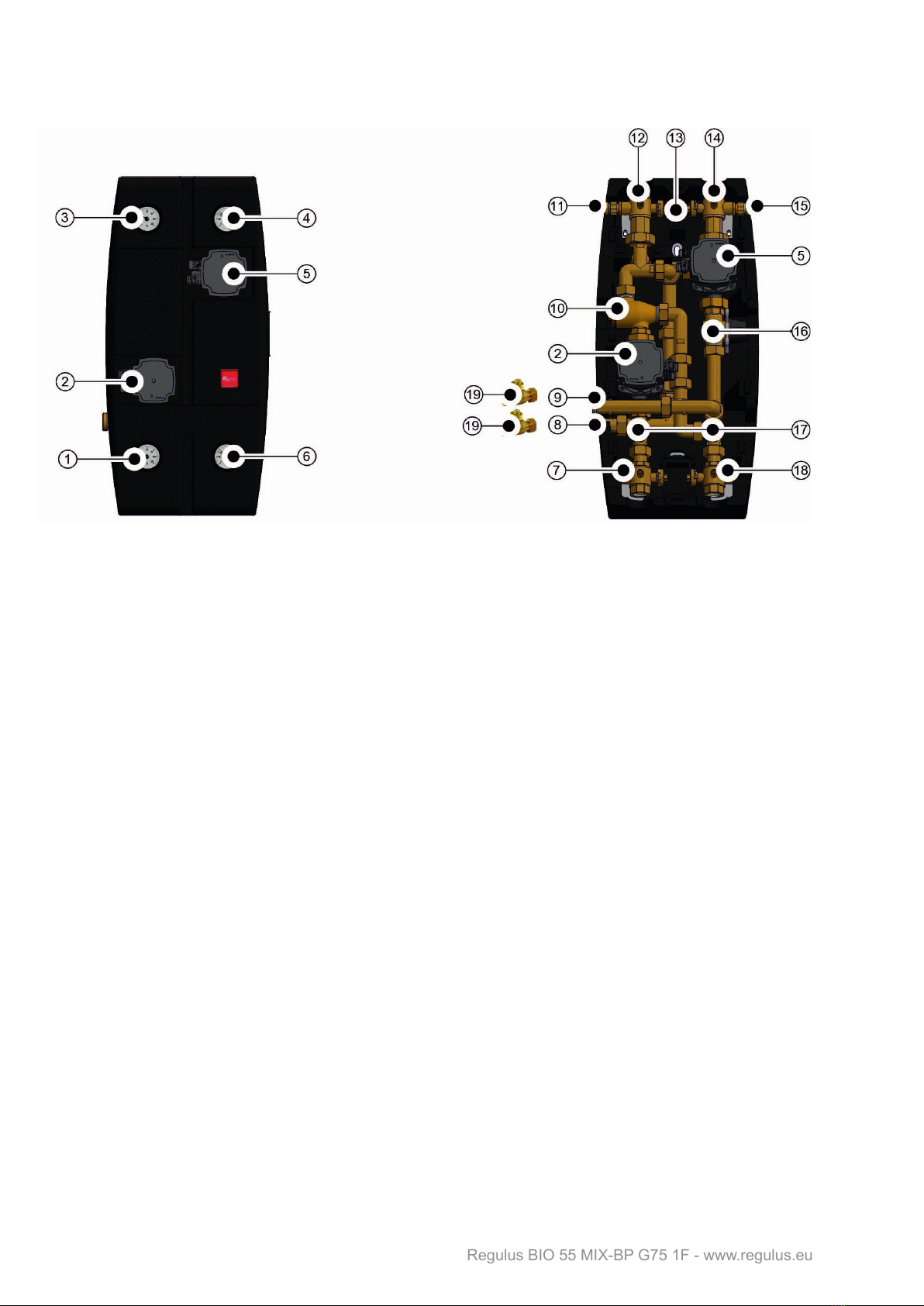
BIO 55 MIX-BP G75 1F Load Unit includes a complete hydraulic connections for the
installation of a heating system with a solid fuel boiler. All you need to do is connect
a suitable controller, boiler, safety elements, one heating system and a thermal
store, then set the desired parameters in the external controller.
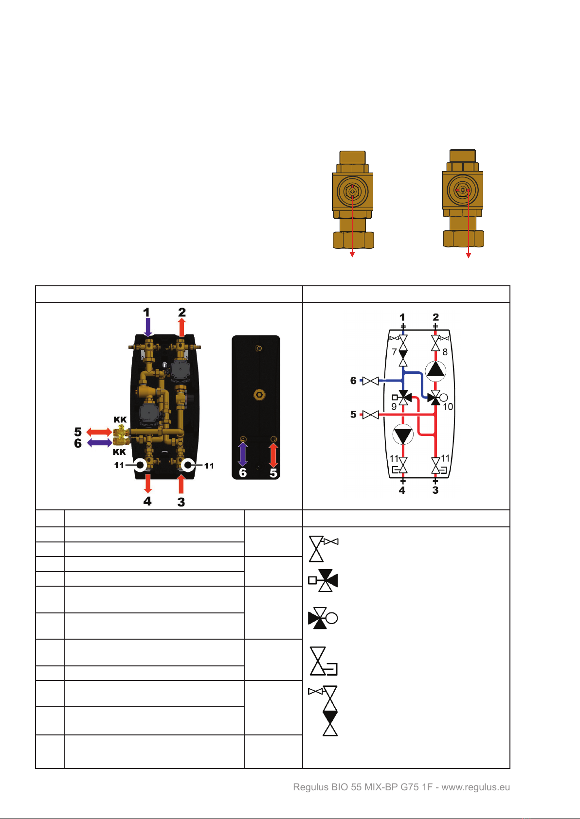
The Load Unit involves
●twoGrundfosUPM3FlexAS25-75circulationpumps(enablingcontroleitherby
PWM signal or by selecting a pump performance curve)
●TSV3BMloadvalvewithautomaticbypassbalancing
●3-waymixingwayformaintainingthedesiredtemperatureintheheatingcircuit*
●twoballvalveswithdrainvalvesforshuttingoffanddrainingtheheatingsystem
●
check valve integrated in the ball valve body located at the return line from the
heating system
●twoballvalvestoshutofftheboilercircuitu
●twodrainvalvestodraintheloadunit
●twoballvalvespermittingtoshutoffthethermalstorecircuit(enclosedinsupply)
●handleforballvalves
●fourthermometers
●
outets for connecting a (combination) thermal store and alternative outlets for
connecting optional accessories
* Mixing valve actuator is not included in supply and shall be ordered separately.
The Load Unit delivery includes a package containing:
Mounting kit:
●2screws,5x50,panhead
●2washers6.4instainlesssteelDIN9021/A2
●2wallplugs,8mm,TX
Others:
●2ballvalvewithunionnut,G1“FuxG1“F

│4
Regulus BIO 55 MIX-BP G75 1F - www.regulus.eu
B.1. LOAD UNIT COMPONENTS
1 – Boiler return line thermometer
2–GrundfosUPM3FlexAS25-75boilerpump
3 – Return heating water thermometer
4–Heatingwaterowthermometer
5–GrundfosUPM3FlexAS25-75heatingcircuitpump
6–Boilerowthermometer
7–G1“Fu×G1“F×G1/2“Fballvalvew.freeoutletandsheathfortemperaturesensor*
8–G1”Freturnlinefromthermalstore
9–G1“Foutlettothermalstore
10–TSV3BMloadvalve
11–G1/2“Mdrainvalvewithhosetail
12–G6/4“Fu×G1“F×G1/2“Fballvalvew.checkvalveandsheathfortemperature
sensor
13 – Handle for ball valves
14–G6/4“Fu×G1“F×G1/2“Fballvalvew.heatingcircuittemperaturesensor
15–G1/2“Mdrainvalvewithhosetail
16–LK840mixingvalve
17 – Mini drain valves
18–G1“Fu×G1“F×G1/2“Fballvalvew.freeoutletandsheathfortemperaturesensor*
19–DN20ballvalvetobemountedonpos.8and9(includedintheenclosedpackage)
* The G 1/2“ F free outlets from ball valves on pos. 7 and 18 can be used for connecting further accessories.
If you do not need to connect any, the outlet remains plugged.

5 │
Regulus BIO 55 MIX-BP G75 1F - www.regulus.eu
B.2. LOAD UNIT DATA
Technical Data
Fluid working temperature 5-95°C
Max. working pressure 6 bar
Min. working pressure 0.5 bar
Ambient temperature 5-40°C
Max. relative humidity 80%,noncondensing
Max. temperature of sheath sensors 95°C
Min. return water temperature to boiler 55°C
Max.boileroutputatowof1730l/h 40kWatΔt20°C
20kWatΔt10°C
Max.heatingsystemoutputatowof1730l/h 40kWatΔt20°C
20kWatΔt10°C
Insulation material EPPRG60g/l
Overalldimensions(HxWxD) 640 x 350 x 210 mm
Total weight 16.5 kg
Code 17553
Electric Data
Load Unit power supply 230 V, 50 Hz
(poweredfromanexternalcontroller)
Load Unit max. power input 120 W
IP rating of the Load Unit IP20
Table of Kvs values
Mixing valve 6.3 m3/h
Ball valves 20.2 m3/h

│6
Regulus BIO 55 MIX-BP G75 1F - www.regulus.eu
B.3. PRESSURE DROP GRAPH
PERFORMANCE CURVES FOR UPM3 FLEX AS 25-75 130 PUMP
BOILER
SIDE
HEATING
CIRCUIT
Curve
(uppergraph) (lowergraph)

7 │
Regulus BIO 55 MIX-BP G75 1F - www.regulus.eu
B.4. DIMENSIONS
Note: The dimensional diagram of the open load unit is rotated for illustrative purposes, the
outlets for the thermal store connection are mutually aligned (see side view).
installation openings
for wall mounting

│8
Regulus BIO 55 MIX-BP G75 1F - www.regulus.eu
C. LOAD UNIT INSTALLATION
The load unit is designed for wall mounting. It shall be mounted in the selected position using
the enclosed installation kit. Two mounting holes in the sheet metal in the rear section of the
insulation are used for wall mounting, see dimension diagram below.
Note: In the basic version, the thermal store is supposed to be connected on the left side of the load unit.
If necessary, the load unit can be converted to be connected to a thermal store on the right side.
Procedure for conversion of the load unit to connect the thermal store from the right
1Remove the top part of insulation. 2
Loosen the nut and remove the extension for
theoutlettothethermalstore(thiswillbeused
instep8).
3
On the right and left side of the insulation
body there are insulated passage points
for connecting the thermal store; take
out the insulation pieces from both the
passage points.
4Loosen the nut and turn the elbow to the right.
5
Take out the insulation piece for the
boiler pump. Loosen the nuts at both the
discharge and suction ports of the pump
so that you can easily handle the pump.
6Move the pump to the side to allow free access
to the elbow.

9 │
Regulus BIO 55 MIX-BP G75 1F - www.regulus.eu
7Loosen the elbow and take it out of the
load unit. 8
Assemble the elbow with the extension
removed in step 3 and re-install it to same
location so that the outlet now points to the
right.
9
Mount the pump back to its original place,
tighten both nuts and return back the
pump insulation piece.
10
Replace all the remaining pieces of insulation
to their original places.
11
The load unit should now look like this.
12
Reinstall the top part of the insulation.

│10
Regulus BIO 55 MIX-BP G75 1F - www.regulus.eu
C.1. HYDRAULIC CONNECTION OF THE LOAD UNIT
HOW TO PROCEED:
Make hydraulic connections of the boiler and safety elements, heating system, thermal
store(s)orhotwatertank(s)withtheloadunit,respectingtheselectedhydraulicvariant(see
the following page). Fill and air bleed the system. Perform a pressure test.
HOW TO CONNECT PIPING:
Connect the piping following the diagram below.
The load unit has two side outlets from ball valves
forconnectingoptionalaccessories(plugged)from
ball valves 11. These outlets are connected with the
boiler even when the ball valves are closed.
Before starting operation, make sure all ball
valves are in the open position(theopen/closed
position on ball valves inside the load unit is shown
by the groove position).
Piping connections Inner hydraulic connection
Pos.
Description Conn. Key to components
1 Return from heating system G1“F
2 Outlet to heating system
3 Flow from boiler G1“F
4 Return to boiler
5Outlet to thermal store w. ball valve
(enclosed) G1“F
6Return from thermal store w. ball valve
(enclosed)
7Ball valve w. integrated check and drain
valves*
8 Ballvalvew.integrateddrainvalve*
9Load valve
10 Mixing valve
11 Ball valve w. outlet to connect optional
accessories*
G1/2“F
(plugged rom the
factory)
Ball valve w. drain
valve
Load valve
Mixing valve
Ball valve w. outlet to
connect optional accessories
Ball valve w. integrated
check and drain valves
* remains connected with the boiler/heating system even when the ball valve is closed
drážka kolmo na směr
proudění
poloha
zavřeno
poloha
otevřeno
drážka ve směru
proudění
open closed
groove in the direction
ofow
groove perpendicular to
thedirectionofow

11 │
Regulus BIO 55 MIX-BP G75 1F - www.regulus.eu
C.2. PUMP CONNECTION
Pump Wiring
C.2.1. Pump Control
ThecirculationpumpcanbecontrolledbyanexternalPWMsignal(proleforuseinheating
systems) or without a PWM signal by selecting a pump performance curve.
Amaximumcurveofapumpworkingrangecanbedened.
- with PWM signal the pump speed changes with the signal value up to the maximum
of the selected curve
- without PWM signal the pump runs at the max. speed according to the selected curve
Performance display
The LED marking is further omitted for better clarity.
N(blue)
L(brown)
PE(yellow-green)
PWMGND(blue)
PWMout(black)
PWMin(brown)
socketforpowersupply(A)
andsignaltransmission(B) powersupply(A)
andsignal(B)terminals
DISPLAY - LED MARKING
DISPLAY PERFORMANCE CURVE STATE Max. H (upper graph)
1LOW PERFORMANCE 5 m
2MEDIUM PERFORMANCE 6 m
3HIGH PERFORMANCE 7,5 m
WARNING: LEDsmaybemirrored,dependingonthespecicpumptype.
GREEN LED FLASHING FREQUENCY PWM SIGNAL RECEPTION
1 flash per second NO
8flashespersecond YES
When switched on, the pump runs at factory settings or the last setting. The display shows
the current pump performance.
Setting selection for UPM3
Toselectyourdesiredsetting,pressthebuttonrepeatedlyuntilyoundthesettingyouneed
(seethepic.above).Ifyoupassthedesiredsetting,youhavetogoonemorerounduntilit
appears again.

│12
Regulus BIO 55 MIX-BP G75 1F - www.regulus.eu
C.3. CONNECTION EXAMPLES
These basic diagrams can be extended with accessories that can always be found after the
respective diagram on the following pages.
C.3.1. Variant 1
A system with a solid fuel boiler w. manual stoking, one heating circuit and a combination
thermal store. The BIO MIX Load Unit ensures DHW and space heating and heat storage in
the combination thermal store.
DESCRIPTION
KK ball valve 1RegulusBIO Load Unit
ZV check valve 2boiler
VK drain valve 3combination thermal store with DHW
REDV pressurereducingvalve(5bar) 4heating system
SVE expansion vessel service valve 5safetykit*
DOCHV thermalsafetyreliefvalve(e.g.BVTS) *thesafetykitinvolvesatestvalve,check
valve, drain valve, safety valve, pressure
gauge and outlet to connect an expansion
vessel
TSV-TV anti-scald valve
PV-TOP heatingsystemsafetyvalve(3bar)
EN-TV DHW expansion vessel
EN-TOP heating system expansion vessel
AOV automatic air vent valve
MFB Magnet Filterball
PV-TV DHW safety valve
To ensure DHW heating also in periods when
the boiler is extinguished, it is recommended
to install an electric heating element tted with
an adjustable and a safety thermostat for DHW
afterheating in the upper section of the thermal
store.

13 │
Regulus BIO 55 MIX-BP G75 1F - www.regulus.eu
C.3.2. Variant 2
A system with a solid fuel boiler w. manual stoking, one heating circuit, combination thermal
store and a thermal store. The BIO MIX Load Unit ensures DHW and space heating and
heat storage in the combination and standard thermal stores. To ensure DHW heating also
in periods when the boiler is extinguished, it is recommended to install an electric heating
elementttedwithanadjustableandasafetythermostatforDHWafterheatingintheupper
section of the thermal store.
DESCRIPTION
KK ball valve 1RegulusBIO Load Unit
ZV check valve 2boiler
VK drain valve 3combination thermal store with DHW
REDV pressurereducingvalve(5bar) 4thermal store
SVE expansion vessel service valve 5heating system
DOCHV thermalsafetyreliefvalve(e.g.BVTS) 6safetykit*
TSV-TV anti-scald valve *thesafetykitinvolvesatestvalve,check
valve, drain valve, safety valve, pressure
gauge and outlet to connect an expansion
vessel
PV-TOP heatingsystemsafetyvalve(3bar)
EN-TV DHW expansion vessel
EN-TOP heating system expansion vessel
AOV automatic air vent valve
MFB Magnet Filterball
PV-TV DHW safety valve

│14
Regulus BIO 55 MIX-BP G75 1F - www.regulus.eu
C.3.3. Variant 3
A system with a solid fuel boiler w. manual stoking, one heating circuit and a thermal
store.
The BIO MIX Load Unit ensures heating of a building and heat storage in the thermal
store.
DESCRIPTION
KK ball valve 1RegulusBIO Load Unit
ZV check valve 2boiler
VK drain valve 3thermal store
SVE expansion vessel service valve 4heating system
DOCHV thermalsafetyreliefvalve(e.g.BVTS)
PV-TOP heatingsystemsafetyvalve(3bar)
EN-TOP heating system expansion vessel
AOV automatic air vent valve
MFB Magnet Filterball

15 │
Regulus BIO 55 MIX-BP G75 1F - www.regulus.eu
C.3.4. Variant 4
A system with a solid fuel boiler w. manual stoking, one heating circuit, a thermal
store and a hot water storage store. The BIO MIX Load Unit ensures DHW and space
heating and heat storage in the thermal store. To ensure DHW heating also in periods
when the boiler is extinguished, it is recommended to install an electric heating element
ttedwithanadjustableandasafetythermostatinthehotwaterstoragetank.
DESCRIPTION
KK ball valve 1RegulusBIO Load Unit
ZV check valve 2boiler
VK drain valve 3thermal store
REDV pressurereducingvalve(5bar) 4hot water storage tank
SVE expansion vessel service valve 5heating system
DOCHV thermalsafetyreliefvalve(e.g.BVTS) 6pump station for heat exchange
TSV-TV anti-scald valve 7safetykit*
PV-TOP heatingsystemsafetyvalve(3bar) *thesafetykitinvolvesatestvalve,check
valve, drain valve, safety valve, pressure
gauge and outlet to connect an expansion
vessel
EN-TV DHW expansion vessel
EN-TOP heating system expansion vessel
AOV automatic air vent valve
MFB Magnet Filterball
PV-TV DHW safety valve

│16
Regulus BIO 55 MIX-BP G75 1F - www.regulus.eu
C.3.5. NECESSARY ACCESSORIES FOR VARIANT 4
Pump station for heat exchange
Pump station for heat exchange ensures heating of hot
waterstoragetank(byheattransferfromathermalstore).
It shall be ordered separately.
Itisrecommendedtousee.g.CSEOTSZVG70(code
15042)orCSEOTSZVG60(code19088).
C.3.6. OPTIONAL ACCESSORIES FOR VARIANTS 1, 2 and 4
The following accessories are recommended for variants 1, 2 and 4.
Electric heating element for DHW afterheating
Hot water always available.
To ensure DHW heating also in periods when the boiler
is extinguished, it is recommended to install an electric
heatingelementttedwithanadjustableandasafety
thermostat – preferably the ETT M model.
The temperature is set directly on the element using
the control knob and thanks to its power cord with an
el. plug no professional electrician is needed for wiring.

17 │
Regulus BIO 55 MIX-BP G75 1F - www.regulus.eu
D. SERVICING, MAINTENANCE
D.1. BOILER AND HEATING CIRCUIT PUMPS
The operating status and possible pump faults are displayed by LED indication directly on
the pump.
FAULT DISPLAY
D.2. BALL VALVES
The ball valves are equipped with a control
shaftwithtwoO-ringswithdimensionsof8.7
x1.8mm.Theseringscanbeeasilyreplaced
after closing the tap, removing the control
element with stop ends and loosening the
packing nut with a # 21 wrench without the
need to drain the system.
Replaceable
O-rings
DISPLAY CONTROL MODE
Seizedpump
Too low supply voltage
Electric fault


©2022 We reserve the right to errors, changes and improvements without prior notice.
REGULUS spol. s r.o.
E-mail: [email protected]
Web: www.regulus.eu
v1.1-01/2022
Table of contents
Other Regulus Industrial Equipment manuals

Regulus
Regulus PS 200 N+ User manual

Regulus
Regulus HSK 350 K P-B User manual

Regulus
Regulus PS 500 E+ User manual

Regulus
Regulus HSK PV Owner's manual

Regulus
Regulus PS 400 K+ User manual

Regulus
Regulus RGMAT E W-iPWM User manual

Regulus
Regulus PS2F 300 N+ User manual

Regulus
Regulus RGMAT E G60 User manual

Regulus
Regulus PSWF 300 N+ User manual
Popular Industrial Equipment manuals by other brands

Manufacturas Lenin
Manufacturas Lenin MLR-270 Operation manual

Winterthur Gas & Diesel Ltd.
Winterthur Gas & Diesel Ltd. X52 Operation manual

SCHUNK
SCHUNK SWG 25 Assembly and operating manual

Siemens
Siemens 3WN6 operating instructions

Siemens
Siemens SIMATIC NET SCALANCE W760 operating instructions

ABB
ABB HT563365 Operation manual