3 │
1 - Description
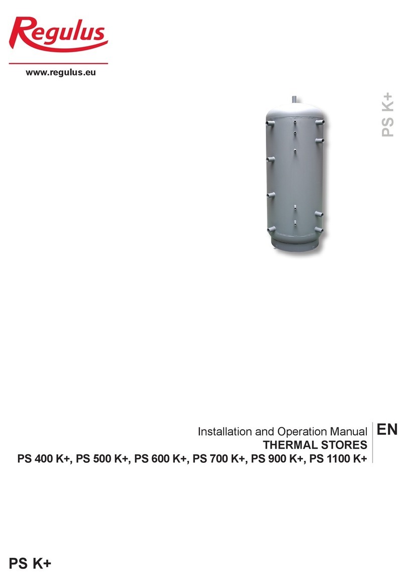
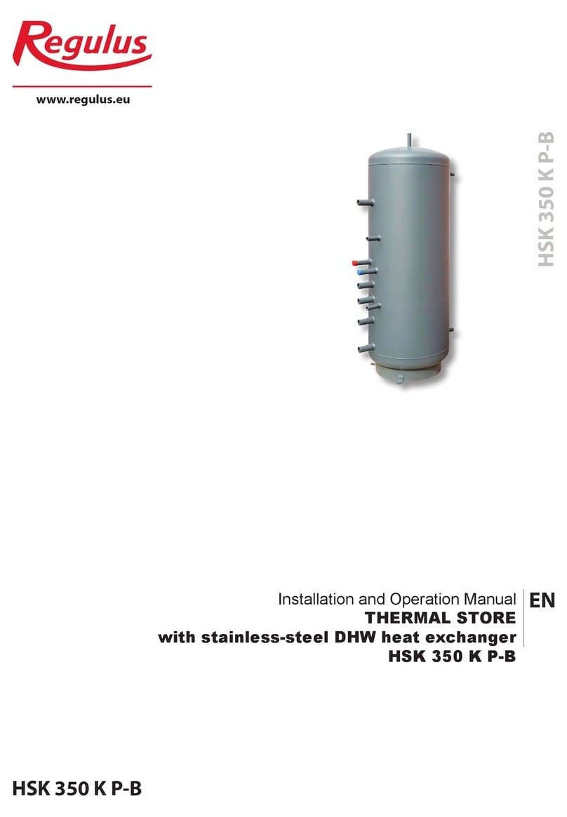
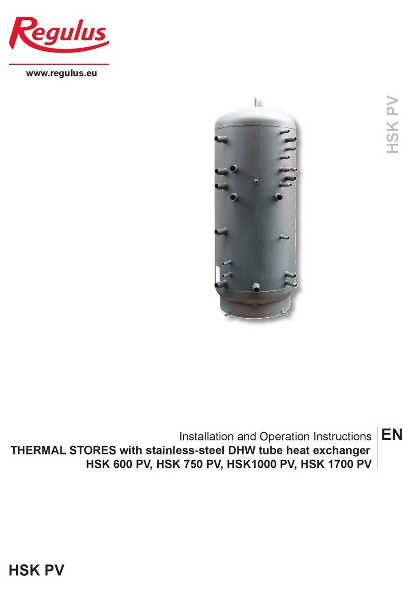
PSWF N+ Thermal Stores are intended for storing and subsequent distribution of thermal energy from solid-fuel red
boilers, heat pumps, solar collectors, electric boilers etc. This thermal store shall be always connected to a sealed
heating circuit with forced circulation. It is tted with one upper ange ready to receive a suitably sized tube heat ex-
changer. A heat exchanger with 1” connections is installed in the bottom part. Mating anges for heat exchangers with
either G 1” or G ¾” connections are available as an option. When no heat exchanger is installed, a blind ange shall
be used (option). These heat exchangers are made of nned copper tubes that feature larger surface area and better
heat transfer. The lower heat exchanger usually connects to a solar system and the upper one is used for DHW heat-
ing (continuous) which limits signicantly the risk of Legionella bacteria formation. The tanks are also tted with nine G
6/4“ side sleeves to connect heat sources, four G ½“ ones for sensor sheaths and one G ½“ connection for
a safety valve. El. heating elements can be installed directly into the 6/4” connections that are located outside the
lower heat exchanger.
In order to reach proper working of the tank, it is necessary to design optimum hydraulics of the whole system, i.e.
position of circulation pumps for sources and heating circuits, valves, non-return valves etc. When more heat sources
shall be combined, it is recommended to use a smart controller, e.g. Regulus IR, for both the source and load sides of
a heating circuit, i.e. also for charging and discharging the thermal store.
1.1 - Models
Six models of 280, 472, 807, 930, 1498 and 1996 l capacity.
1.2 - Tank protection
The inner surface has no nish, no anticorrosion protection, the outer surface is lacquered in gray.
1.3 - Thermal insulation
Thermal insulation is available as a separate item. For easier handling, the insulation shall not be tted on the tank
until it reaches its denite place of installation. The insulation is made of eece, 100 mm thick, with a hard polystyrene
surface. It is closed by a quick lock.
1.4 - Connection points on the tank
1 ange with 210 mm inner diam.
8 side connections in a 90° sector, G 6/4” F thread
1 top connection, G 6/4” F thread
4 side connections for sensor sheaths, G ½” F thread
1 side connection for a 3 bar safety valve, G ½” F thread
2 side connections for a heat exchanger, G 1” F thread
1.5 - Packing
Tanks are delivered standing, each screwed to its pallet, packed in bubble wrap.
Included in the package are gaskets, bolts for the ange.
2 - General Information
This Owners Manual is an integral and important part of the product and must be handed over to the User. Read care-
fully the instructions in this Manual as they contain important information concerning safety, installation, operation and
maintenance. Keep this Manual for later reference. The appliance shall be installed by a qualied person according to
valid rules and Manufacturer‘s Instructions.
This appliance is designed to accumulate thermal energy of heating water and distribute it subsequently. It shall be
connected to a heating system and heat sources. The equipment is suitable also for continuous water heating. In such
a case, the customer needs to buy a suitably sized heat exchanger (available as accessory) and have it installed into
the ange.
Using the thermal store for other purposes than above described (e.g. as a DHW tank) is forbidden and the
manufacturer accepts no responsibility for damage caused by improper or wrong use.
