Regulus RGMAT E W-iPWM User manual

www.regulus.eu
RGMAT E W-iPWM
RGMAT E W-iPWM
EN
Installation and Operation Manual
RegulusRGMAT E W-iPWM LOAD UNIT
with PARA 25/8 for heating systems

│2
1. Introduction
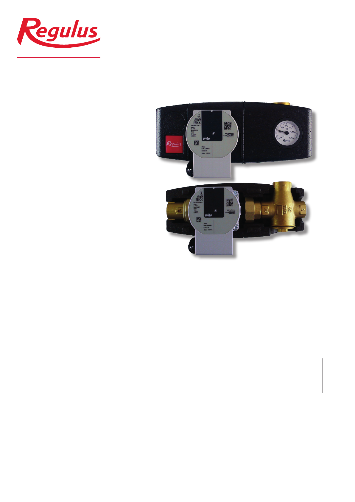
RegulusRGMAT E W-iPWM Load Unit makes boiler installation quicker as it contains all components
needed for boiler circuit circulation and for boiler protection against low-temperature corrosion. It is
designed to be installed directly on return piping. The distance of pipe axis from a wall shall be at least
100 mm to enable insulation removal if needed.
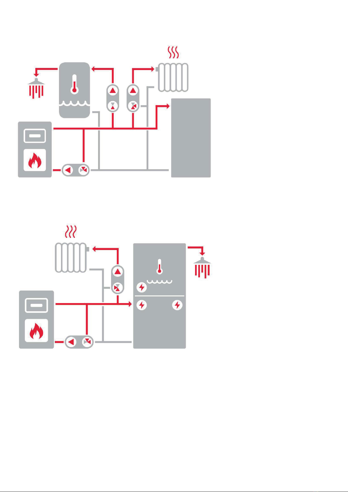
This Load Unit is intended for hydronic fireplaces and solid-fuel boilers.
2. RGMAT E W-iPWM Load Unit Description
RGMAT E W-iPWM keeps the temperature in a hydraulic boiler circuit above the flue gas condensation
temperatures, which prevents so called low-temperature corrosion of the boiler combustion chamber.
This limits condensation and boiler tarring significantly, the efficiency of fuel combustion increases and
service life of the boiler is extended.
Main Features
Function maintaining stable inlet temperature into a boiler (fireplace)
through a load valve
Application Load Unit for solid-fuel boilers and fireplaces; it prevents low-
temperature corrosion and boiler (fire) fouling
Description
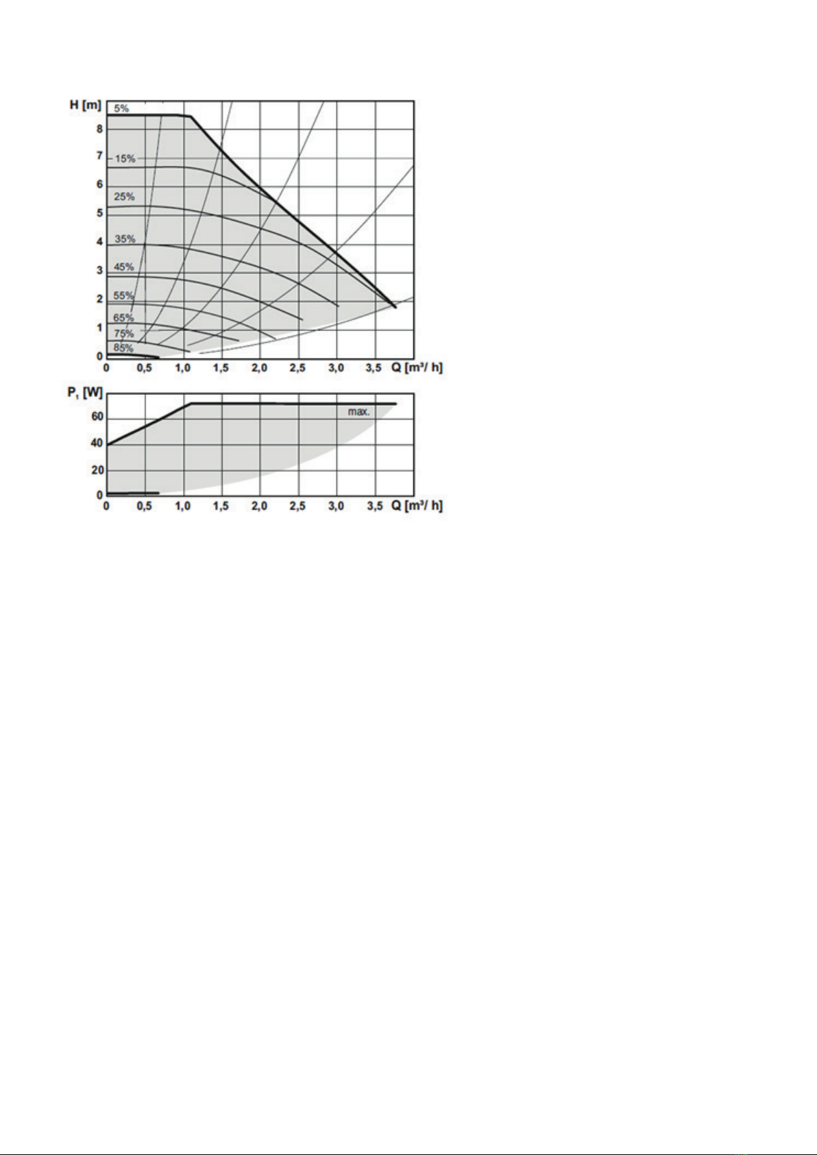
consists of Wilo PARA 25/8 iPWM1 pump, fittings w. integrated
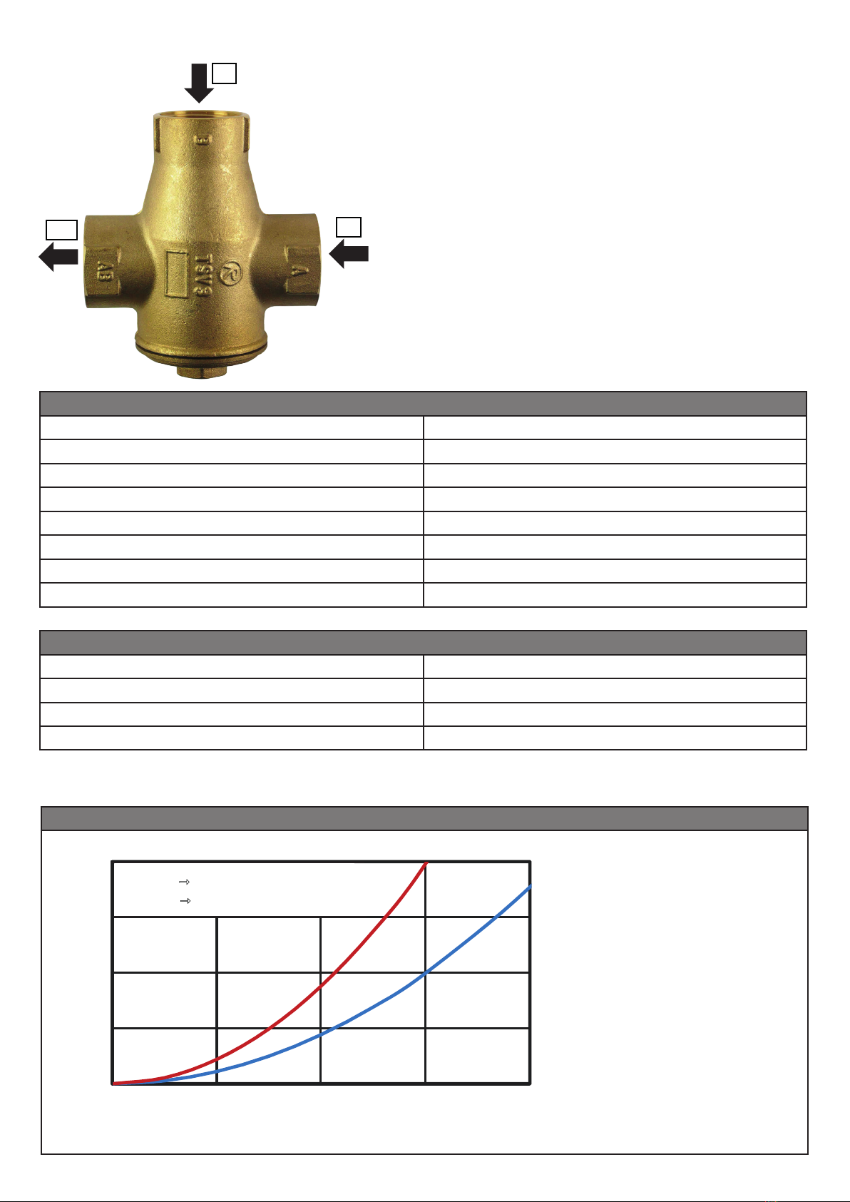
ball valve, TSV3B valve (with automatic bypass balancing),
thermometer and insulation
Working fluid water; water/glycol mixture (max. 1:1) or water-glycerine
mixture (max. 2:1)
Installation on return piping, min. distance of the pipe axis from a wall is 100 mm
Codes max. boiler output
18131 for 65°C opening temperature 31 kW
18133 for 55°C opening temperature 44 kW
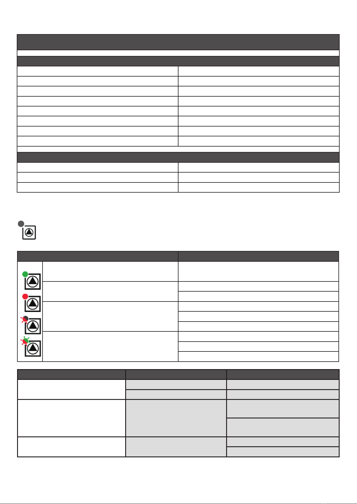
Data for RGMAT E W-iPWM Pump Station
Fluid working temperature 5 - 95 °C
Max. working pressure 6 bar
Min. working pressure 0.5 bar
Ambient temperature 5 - 40 °C
Max. rel. humidity 80 % non condensing
Power supply 230 V, 50 Hz
Insulation material EPP RG 60 g/l
Overall dimensions 305 x 170 x 135 mm
Total weight 3.3 kg
Connections 3x G 1" F
Accessories
Bypass with non-return valve code 16 126

3 │
3. RGMAT E W-iPWM Connection Diagram
Install the Load Unit respecting the following instructions:
Connect the Load Unit outlet marked AB to the piping entering the boiler. Connect the return line from
the heating system to the Ainlet, and the outlet pipe from the boiler to the Binlet via a T-piece. Take
care to install shut-off valves where necessary to avoid draining the whole system for valve cleaning or
replacing the thermostatic element.
When the connecting pipes are not arranged or sloped properly, the thermostatic valve may get
blocked by air inside. This may hinder or even disable its operation.
Always respect valid rules and boiler manufacturer’s data during installation.
Example of possible connection I
Example of possible connection II
The diagram shows a typical
connection of a solid fuel boiler,
thermal store and heating circuit
(with the recommended
CSE MIX W pump station – not
included in supply). If the boiler
is used also for hot water heating,
it is recommended to install
a CSE OTS ZV W pump station
(not included in supply).
The diagram shows a typical
connection of a solid fuel boiler,
combination thermal store and
heating circuit (with the
recommended CSE MIX W pump
station – not included in supply).
Hot water storage tank
RGMAT E W-iPWM Thermal store
CSE OTS ZV W
CSE MIX W
RGMAT E W-iPWM
CSE MIX W
Combination thermal store

│4
4. Function description of TSV3B valve
Technical Data
Max. working temperature 95 °C
Max. working pressure 6 bar
Valve opening temperature depending on the thermostatic element
Control range tvalve,opening + 5 °C
Valve Kvs (A→AB direction) 6.2 m³/h.
Valve Kvs (B→AB direction) 4.4 m³/h
Connections 3x G 1" F
Nominal inner diameter DN 25
Materials
Housing, cone and plug brass
Spring stainless steel
Element and plug seals EPDM
Cone seal NBR
Valve pressure drop graph
The pressure drop value
moves between the two cur-
ves depending on the mixing
ratio during mixing.
0,0
0,3
0,6
0,9
1,2
0,0 0,5 1,0 1,5 2,0
Δp [m H
2
O]
Q [m
3
/h]
▬▬
A AB, Kvs = 6,2 m3/h
▬▬
B AB, Kvs = 4,4 m3/h
B
AB A
The TSV3B load valve is fitted with an integrated
thermostatic insert that will close the Ainlet (from a heating
system), if the return water temperature to the boiler (AB
outlet) is lower than the opening one. As soon as the
opening temperature is reached, the thermostat starts
opening the Ainlet slowly and mixing the cold return water
with the hot water from the Binlet (boiler flow) with the
aim to reach the opening temperature (AB outlet) in the
return pipe.
At the same time, the valve closes the Binlet, limiting so
the hot water flow coming from the bypass till its complete
tight closure. Thanks to this, no balancing valve is needed.
The load valve is made of brass, element and plug seals
are in EPDM, cone seal is made of NBR.

5 │
5. Wilo-Para iPWM1 Pump
5.1. General Info
The Wilo Para 25/8 iPWM1 is a wet running circulation
pump. The pump speed is controlled by the PWM signal.
When the PWM signal is disconnected, the pump runs at its
maximum speed. The operating status and possible faults of
the pump are indicated by LEDs directly on the pump. The
pump is able to send the current flowrate electronically to an
external controller. The controller must be equipped with an
iPWM read input and a flow calculation function.
The high efficiency circulation pumps of the PARA iPWM1
series are used exclusively for the circulation of liquids in
hot water heating systems. Operating the pump in other
systems or in systems containing too little water, air bubbles
or not pressurized can lead to its rapid destruction.
5.2. Permitted and Prohibited Pump Positions
Permitted Pump Station positions Prohibited Pump Station positions
5.3. Pump Wiring
The pump must be wired / disconnected by a qualified person in compliance with EN 50110-1!
Wilo PARA 25/8 iPWM1 pump wiring
L (brown)
N (blue)
PE (yellow-green)
PWM in (brown)
PWM GND (blue)
iPWM out (black)
1.POWER SUPPLY (230 V, 50 Hz 2.CONTROL (PWM)

│6
5.4. Technical Data
Wilo PARA 25/8 iPWM1
Electric Data
Power supply 230 V, 50 Hz
Power input (min./max.) 2 / 75 W
Current (min./max.) 0.03 / 0.66 A
Max. speed 4800 rpm
Speed control frequency converter
Energy Efficiency Index ≤ 0,21 by EN 16 297/3
IP rating IPX4D
Motor protection integrated
Operating Parameters
Fluid working temperature 0 - 95 °C
Max. static pressure 10 bar
Max. head 8.4 m
5.5. FAULTS AND THEIR REASONS
The LED light signals a defect. The pump will switch off (depending on the defect type) and
try to restart.
LED signals State description and possible fault reasons
GREEN IS LIT 1 - pump is running in trouble-free operation
RED IS LIT 1 - rotor is blocked
2 - electric motor winding defect
FLASHING RED
1 - power supply lower/higher than 230 V
2 - electric short circuit in pump
3 - pump overheated
FLASHING RED AND GREEN
1 - unforced uid circulation through the pump
2 - pump speed lower than desired
3 - air in pump
FAULTS REASONS TROUBLESHOOTING
The pump is not running despite
the power supply turned on
Faulty electrical fuse Check the fuses
The pump is not energized Remove the power interruption
The pump makes noises Cavitation due to insufficient
inlet pressure
Increase the pressure within the
permitted range
Check the head adjustment, or
set a lower head
The building is not warming up Heat output of heating
surfaces too low
Increase the desired value
Set the control method to Δp-c
If the fault cannot be rectified, contact a qualified technician.

7 │
5.6. Performace curves for Wilo Para 25/8 iPWM1 pump

SMĚR PROUDĚNÍ
SMĚR PROUDĚNÍ
SMĚR PROUDĚNÍ
6. Installation options
This Load Unit comes in the version for horizontal installation to the right of a boiler. However, it can be
installed also into vertical piping or horizontally to the left of a boiler. When being installed horizontally
to the left of a boiler, the Load Unit needs to be turned by 180° and the TSV3B valve turned as shown
in the pics below.
FLOW DIRECTION
FLOW DIRECTION
FLOW DIRECTION
©2022 We reserve the right to errors, changes and improvements without prior notice.
REGULUS spol. s r.o.
Web: www.regulus.eu
v1.2-08/2022
Table of contents
Other Regulus Industrial Equipment manuals

Regulus
Regulus PS 200 N+ User manual

Regulus
Regulus BIO 55 MIX-BP G75 1F User manual

Regulus
Regulus PS2F 300 N+ User manual

Regulus
Regulus HSK 350 K P-B User manual

Regulus
Regulus HSK PV Owner's manual

Regulus
Regulus PS 500 E+ User manual

Regulus
Regulus PSWF 300 N+ User manual

Regulus
Regulus RGMAT E G60 User manual

Regulus
Regulus PS 400 K+ User manual