Regulus KPG1-ALC User manual

1
1
Solar System with KPG1-ALC Collectors
EN
v. 1.4
Installation and Operation Manual

2
CONTENTS
General Installation and Operation Instructions .…....……...…….…................................. 3
1 Supply of Mounting System ..……........……...……..………....……..……............................ 4
2 Sloping Roof Mount ..........................................………………………................................. 5
2.1 Preparation ...………………………………………....………............................................ 7
2.1.1 Roof anchor installation for sloping roofs ..……………………................................ 7
2.1.2 Installation with roof anchors and rafters ………………………............................... 7
2.1.3 Installation with roof anchors for slate, shingle or metal roofs ............................... 8
2.1.4 Installation with bolts for fitting rails onto a roof .................................................... 8
2.2 Installing rails onto roof anchors ….........……………………………............................... 10
2.3 Collector mounting …………………………….………………………............................... 10
3 Connection Pipe Passage through a Roof …...…...…................................................... 11
4 Flat Roof Mount …………....……….…………………........................................................ 12
4.1 Overview ………..........…….……………….………………………................................. 12
4.2 Flat roof support mounting ………………….....………….............................................. 14
5 Hydraulic Connection …………………………………………………................................. 16
5.1 Collector connecting .......………………………………………………............................ 16
5.2 Collector interconnecting …………………..…………………………............................. 16
6 Temperature Probe Positioning …………………………………….................................... 18
7 Pump Station ………………………………………..........…………...................................... 19
8 Expansion Vessel Sizing and Working Pressure Calculation ………........................... 20
8.1 Expansion vessel sizing ……………………………...…………..................................… 20
8.2 Calculation of a system working pressure ……………..………................................… 20
8.3 Calculation of an expansion vessel preset pressure …………................................…. 20
8.4 Examples of calculating working pressure and expansion vessel pressure ...........…. 20
8.4.1 Example of calculating system working pressure ………......................…………. 20
8.4.2 Example of calculating expansion vessel pressure …………...................………. 20
9 Installation of Air Release Valves …………………..………….….................................…. 21
10 System Filling, Flushing, Leak Test and Air Bleeding …............................................. 22
10.1 Filling ……………………………………......………………………....................………. 22
10.2 Flushing …………………………………………........………………..................………. 22
10.3 Air bleeding …………………………….................……………….....................………. 22
10.4 Leak test ………………….............................….……………………....................……. 22
11 Commissioning …………..……...............................................................................……. 23
12 Operation, Checks and Maintenance ………........…………………...........................…. 23
13 Servicing and Warranty …………..................………………………….........................…. 23
14 Technical Data .…...…...................................................…...….....................…............… 24
15 Connection dimensions…………………..……...........................................................…. 26
16 Annual Check Description ............................................................................................. 27
Service sheet ......................................................................................................................... 28

3
Collector description
REGULUS Flat Solar Collectors are designed for solar
domestic hot water heating (DHW), backup- and pool
heating with solar energy. Solar radiation penetrates the
glass and is intercepted by an efficient absorption layer
applied on an all aluminum absorber. The heat is then
transferred into heat transfer fluid. The absorber is sea-
led in a compact frame with high quality thermal insulati-
on. The collectors are designed for year round operation,
that’s why they work in a separate primary circuit filled
with antifreeze heat carrier.
The collectors are not intended for direct wa-
ter heating. If different heat transfer fluid is used
than specified by the manufacturer, irreversible
damage to the collector may be done.
Transport, handling and storing
Collectors shall be transported in their original packing,
in upright position (standing on their shorter side) or lying
horizontal with glass upwards, stack of max. 14 pieces
on a pallet.
During handling the collector glass shall be always
facing upwards.
Please check the condition of the collector upon recepti-
on from your supplier or forwarder. Later claimed mecha-
nical damage (frame, glass, connection) will be refused.
When stored, the collector shall not be exposed to rain
and its absorber exposed to solar radiation.
Scope of supply
1. KPG1-ALC collector
2. Instruction manual
3. Warrant Certificate
General instructions for installation
The installation must be done by a trained worker or a
specialized company.
During installation and before commissioning, it is
necessary to cover collectors in order to avoid overhea-
ting and possible burn injury to the installer.
Prior to installation, conditions set by the roofing manu-
facturer and the max. permissible roof load shall be
checked.
Mounting method for solar collectors shall always re-
spect local conditions, i.e. roof inclination and weather
influence on the overall load on the collector. Kindly con-
sult the fastening method with a structural statics expert.
During installation the collectors and accessories shall
be handled carefully. Defects caused by improper hand-
ling or DIY installation are not cover by warranty.
Generally valid rules and standards for occupational
safety shall be respected during installation. This con-
cerns mainly technicians walking on a roof and the secu-
ring the area against objects falling down from a roof.
Only REGULUS mount elements may be used. Other
fastening elements may be used only with a written
approval from REGULUS company.
Collectors shall not be exposed to solar radiation un-
til commissioned. The absorption surface may get
damaged.
Collectors shall be installed and operated in compliance
with this Manual and with respective generally valid rules
and norms.
Collector placing
The collector must be placed outdoors. The glass
absorption surface should be orientated to South, with
deviations not over 45° (Southwest or Southeast). For a
year round operation the right inclination angle is 40°-
50°, for summer operation smaller inclination is better
(30°).
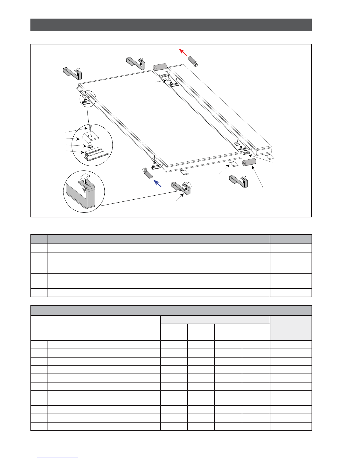
Collectors are installed according to marking.
The collectors shall be installed at an angle
between 15° and 75°.
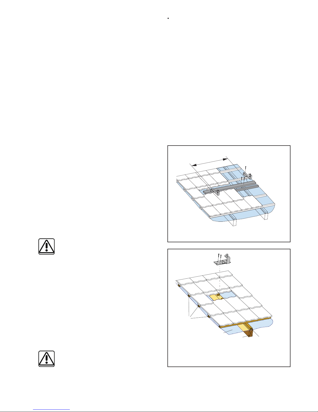
On inclined roofs it is recommended to install
solar collectors as close to the roof ridge as possible.
Should this solution be impossible, then protections
against snow slide shall be installed above the collec-
tors.
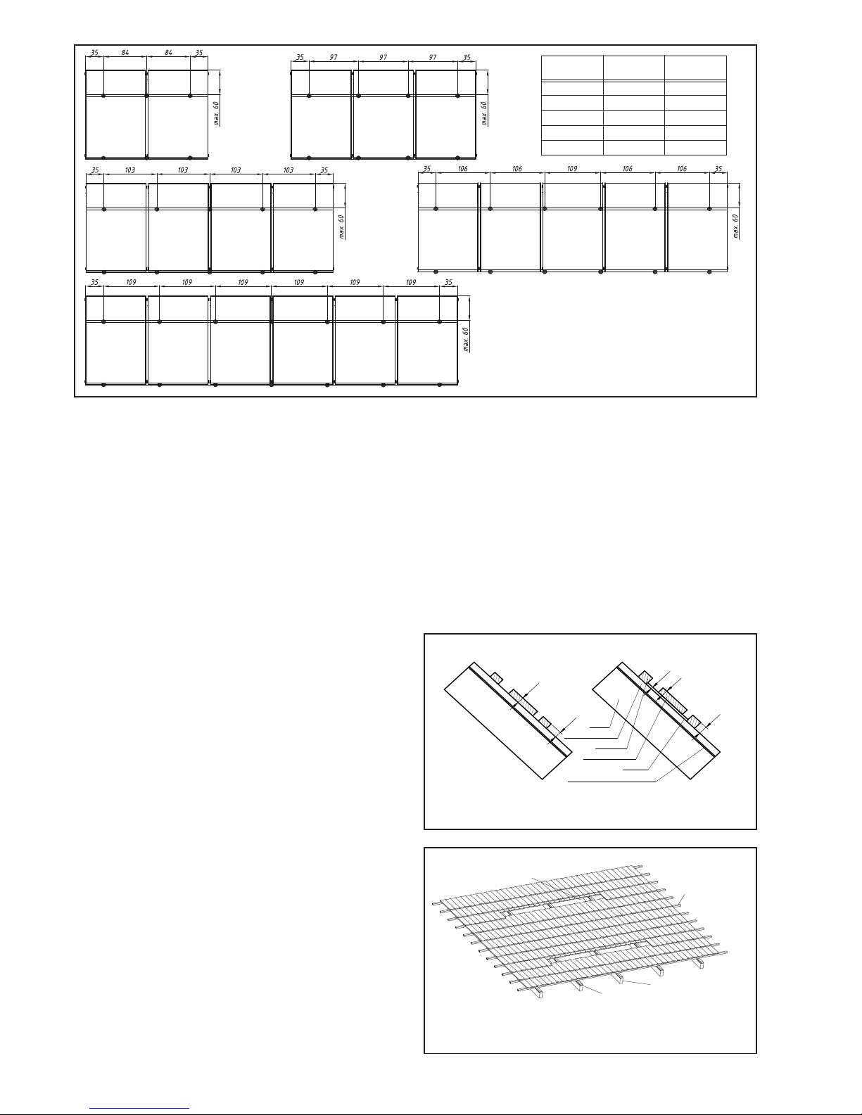
The numbers of roof anchors shown in the Mount Kits
for Fitting and Connecting Regulus Solar Collectors are
designed for the following load:
Max. permissible snow and wind load ≤1,8 kN/m2
Max. permissible wind load - negative pressure ≤1,0 kN/m2
The customer/user shall be informed about this fact prior
to starting installation of a solar system. If a higher load
than shown above is expected in the area in question, a
statics expert shall be consulted and more roof anchors
designed, or other measures taken that would ensure
safe collector fitting. Regulus refuses any responsibility
for damage caused by wrong design of collector faste-
ning.
GENERAL INSTALLATION AND OPERATION INSTRUCTIONS

4
Mounting kits for fitting and connecting KPG1-ALC solar collectors Code
Connection kit for a KPC1, KPS11, KPG1,KPH1, KTU collector array
(3/4“ M inlet and 3/4“ M outlet with a pocket for solar temperature sensor) 7710
Connection kit for KPG1 collector array, landscape installation 14134
Mount kit for one KPG 1 collector *[for 4 anchors or 2 supports+1 strut] 10538
Mount and interconnection kit for 2 KPG 1 collectors *[for 6 anchors or 3 supports+1 strut] 10539
Mount and interconnection kit for 3 KPG 1 collectors *[for 8 anchors or 4 supports+1 strut] 10540
Mount and interconnection kit for 4 KPG 1 collectors *[for 10 anchors or 5 supports+1 strut] 10541
Mount and interconnection kit for 5 KPG 1 collectors *[for 12 anchors or 6 supports+1 strut] 14067
* Roof mount and interconnecting kits are necessary to create a hydraulically connected collector array
fitted to 2 mounting rails. The kits contain interconnecting fittings with insulation, two mounting rails,
fastening material for mounting collectors onto the rails. They do not involve any roof anchors, supports,
struts. These shall be selected from the following chart by the roof type and roofing material.
Supports and struts for flat roof installation Code
Triangle support strut 15° 11979
Triangle support strut 25° 10975
Triangle support strut 45° 6859
Strut incl. screws for triangle support 9563
Supports for sloping roof installation Code
Triangle strut 15° 10748
Triangle strut 25° 8805
Triangle strut 45° 10094
Triangle strut 60° 9631
Anchors for various roofing types Code
Stainless-steel anchor for slate roofs 11574
Anchor for pantiles - hot-dip galvanized steel 7929
Aluminum anchor for pantiles - rafter mounted 6932
Stainless-steel anchor for pantiles 6857
Stainless steel anchor for pantiles - rafter mounted, incl. self tapping screws 10159
Bolt for fitting rails onto a roof 7320
1. DELIVERY OF MOUNTING SYSTEM
Supports and support strut for horizontal installation on flat roof Code
Triangle support strut 25° 10907
Triangle support strut 45° 10921
Support strut incl. bolts for triangle supports, for horizontal installation on flat roof 10908
Supports for horizontal installation on sloping roof Kód
Triangle strut 15° for horizontal installation on sloping roof 11070
Triangle strut 25° for horizontal installation on sloping roof 11071
Triangle strut 45° for horizontal installation on sloping roof 11072
Wall Bracket for KPG1, landscape, pitch 45° 12786

5
Pos. Item Code
1 Flat plate collector 10336
2 Roof anchor with M8 bolt/special head for rails
6857 or other,
depending on
roofing type
Triangle struts for inclination adjustment, suitable for anchors for sloping roofs - 15°, 25°,
45° and 60° angle
10748, 8805,
10094, 9631
Interconnecting pipes
Mount and interconnection kits No. of collectors (kit code) Item code123 4
(10538) (10539) (10540) (10541)
3 Aluminum rail, 2 pieces 1.22 m 2.44 m 3.69 m 4.92 m 6949
4 M8 nut for the rails 4 pcs 6 pcs 8 pcs 10 pcs 6925
5 M8 ×16 bolt with allen head 4 pcs 4 pcs 4 pcs 4 pcs 6926
6 Retaining side bracket 4 pcs 4 pcs 4 pcs 4 pcs 10522
10 Retaining bracket between 2 collectors - 2 pcs 4 pcs 6 pcs 10673
7 Retaining bracket for collector bottom 2 pcs 4 pcs 6 pcs 8 pcs 13057
8Compression nut and ring for collector inter-
connection - 2 pcs 4 pcs 6 pcs 7629
9 Insulation 35 mm diam., 19 mm thick 0.5 m 0.75 m 1 m 1.5 m 7188
11 H-rail end plug 4 pcs 4 pcs 4 pcs 4 pcs 11773
Insulation tape 0.8 m 1 m 1.5 m 2 m 7227
1
8
3
2
6
7
5
4
9
10
2. SLOPING ROOF MOUNT
Fig. 1 Collector installation on sloping roof

6
Mount and interconnection kits for landscape installation, landscape connection kit
No. of collectors (kit code) Item code12
Connection kit
(10700) (10701) (14134)
3 Aluminum rail, 2 pieces 2.20 m 4.40 m - 6949
4 M8 nut for the rails 4 pcs 6 pcs - 6925
5 M8 ×16 bolt with allen head 4 pcs 4 pcs - 6926
6 Retaining side bracket 4 pcs 4 pcs - 10522
7 Retaining bracket for collector bottom 2 pcs 4 pcs - 13057
9 Insulation 35 mm diam., 19 mm thick 0.5 m 0.7 m - 7188
10 Retaining bracket between 2 collectors - 2 pcs - 10673
11 H-rail end plug 4 pcs 4 pcs - 11773
Insulation tape 0.8 m 0.8 m - 7227
Threaded fittings 22-3/4“ M - straight, no plug - 2 pcs 2 pcs 13695
22 mm nipple, blind - 2 pcs 2 pcs 13696
Nipple 3/4“ M/M, thick wall - 4 pcs 2 pcs 6970
3/4“ FF elbow, brass - 1 pcs 1 pcs 10192
T-piece in brass, 3/4“ FFF - 1 pcs - 7180
X-piece in brass, 4x 3/4“F - - 1 pcs 7184
3/4“ plug + gasket, brass (for code 7628) - - 1 pcs 7954
1/2“-3/4“ F/M brass hex nipple - - 1 pcs 6964
Single sheath, 7x8 x 200 mm, 1 sensor, 1“ - - 1 pcs 7217
Capillary spring, small, 1/2“, stainless steel - - 1 pcs 10845
Expansion mount and interconnection kits for 1 KPG1 solar collector Code
Expansion mount and interconnection kit for 1 KPG1 solar collector 11986
Expansion mount and interconnection kits for 1 horizontal KPG1 solar collector 11987
3RþHWNROHNWRUĤ&HONRYiGpOND 3RþHWKiNĤ
1215cm4
2 430 cm 6
180 180
35 35
cca 38
145
35 35
cca 38
Fig. 2b: Roof anchor fastening for landscape collectors
No of collectors Overall length No of anchors

7
2.1 Prior to installation
Prior to installation of solar collectors, select a suitable
position respecting the following conditions:
• roof facing South
• roof inclination (25°- 45°)
• unshaded place
• accessible for servicing
• permissible roof load
• shortest possible distance between the collectors and
(accumulation) tank
Further have ready the necessary material, tools and
safety equipment for working on a roof.
Check if the roofing manufacturer offers roof hooks and
if the roof warranty will not be violated.
2.1.1 Installation with roof anchors and au-
xiliary boards
Prior to installing anchors on auxiliary boards, the fo-
llowing shall be ensured:
• The auxiliary board length shall exceed the length of
the rail by at least 200 mm on each end.
• The auxiliary board width shall be between 100 and
200 mm.
• It shall be 30 mm thick.
• The height of the auxiliary board from the counter
batten shall be equal to the batten thickness which
can be reached by underlying the auxiliary board (see
Fig. 3).
Installation
• Remove roofing so that auxiliary boards can be
inserted (approx. distance between boards 1600-1800
mm). For roof tiles, just shifting them upwards in the
length of the auxiliary board is sufficient (see Fig. 4).
• Fit the auxiliary boards to battens so that the distribu-
tion of anchors resembles the positions in Fig. 2. At
the same time screw the boards so high that the roof
anchor does not hinder placing the roof tile with the
right overlap (see Fig. 8).
• Hang the roof anchors onto the auxiliary board
respecting their distribution shown in Fig. 2.
• Fit the anchors using stainless steel screws.
2.1.2 Installation with roof anchors for rafters
For tiled roofs, rafter anchors can be used. Either a fixed
(not adjustable) stainless-steel hook (Fig.7a) can be
used, or an adjustable aluminum anchor (Fig. 7b) that
enables horizontal shift of the anchor along the fastening
40
30
10
30
30
auxiliary board
battens
counter batten
rafter
waterproofing membrane
underlay
No. of collectors Total length No. of anchors
2238cm6
3361cm8
4482cm10
5603cm12
6724cm14
room for an auxiliary board
counter batten
rafter
roof battens
Fig. 3: Underlay to match thick battens
Fig. 4: Remove roof tiles to fit the board
Fig. 2: Layout of roof anchors
auxiliary board width is
100 - 200 mm

8
board. For this anchor type also the rail fitting height can
be adjusted.
Installation
• Remove roofing in places where anchors shall be fitted
(Fig. 5). The distance “a” between anchors is defined
in Fig. 2.
• Cut the counter batten used for fastening the waterpro-
ofing membrane.
• Prior to the installation itself, use an underlay for
anchors according to the thickness of battens and
counter battens so that the anchors installed do not
hinder proper positioning of the roof tiles.
• Screw the adjustable aluminum anchor to a rafter and
move it in the groove horizontally so that it doesn’t
hinder proper positioning of the roof tile. If a fixed
stainless steel anchor is used, its position shall be
adjusted before faastening.
• Fit all the other roof anchors in the same way.
• When installing roof anchors, maintain a direction
parallel to the roofing (horizontal).
2.1.3 Installation with roof anchors for shin-
gle or metal roofs
• Depending on the number of collectors, measure and
calculate the positions for fiting roof anchors (Fig. 2).
Such places shall be selected for mounting where an-
chors can be fastened sufficiently into the roof frame
(rafter or similar).
• Prior to fitting the anchor, apply suitable silicone putty
on the contact surface (adjacent to the roofing) in or-
der to prevent water leaking, or possibly use a sealing
method recommended by the roofing manufacturer.
• Simply lay the anchor onto the roof tiles and fasten it
with stainless-steel bolts.
If the roofing is made of e.g. copper or zinc-pla-
ted iron, then the anchor contact surface shall be
isolated using suitable underlay (rubber). Other-
wise there is a risk of contact corrosion.
2.1.4 Installation using bolts for fitting rails
onto a roof
This method of installation is preferably used for roofs of
bitumen corrugated sheets like Gutta or Onduline etc., or
for corrugated eternit or metal sheets.
Installation:
• Depending on the number of collectors, locate the
places for drilling holes and installing bolts into the ro-
ofing (Fig. 6e). Pre-drill 6 mm diam. holes into a rafter
or another massive wooden roof element for the bolts.
Holes should be always drilled in the crest
of the roofing wave, not in its valley, to avoid
leakage.
counter
batten
rafter
roof
battens
waterproofing membrane
a
• The bolt shall be screwed into a rafter or another
massive wooden roof element (see 2.2.3) using spa-
nner No. 7.
• After screwing the bolt in, put on the rubber seal (Fig.
6e) and using a washer and nut, seal the drilled hole.
• Then mount the U-shaped bracket (Fig. 9) on the
bolt, between two nuts with a serrated washer.
• Then M8 bolt with floating head (for rails) shall be
mounted into the other end of the bracket. First insert
the floating head into the groove of the rail, and then
tighten the bolt together with the rail to the U-shaped
bracket using a nut and a serrated washer.
Fig. 5: Fitting an auxiliary board and roof anchors
Fig. 6: A place for mounting a roof anchor on a
rafter - detail

9
70
ø 9
80
130
40
40
9
(138)
70
58
300
100
35
2× Ø6
80
6
150
120
136−156
65.5
40
Ø 9
54
56
180
Fig.7: Basic overview of fastening elements
150
80
125
≈160
35
Ø 10
40
45
150
7
5
e) Roofing bolt for rail fastening
RIGHT
10 - 30 mm
Fig. 8: Right anchor position with roof tiles
c) Roof anchor of stainless steel
or zinc-plated steel for pantiles
a) Stainless steel anchor on rafter, for pantiles,
incl. screws b) Aluminum anchor on rafter, for pantiles
d) Stainless steel roof anchor for metal
or slate roofing
RIGHT !
70
230
35
2× Ø6
72
6

10
2.2 Fitting rails on roof anchors
• have ready two rails in the length required for the
number and type of collectors to be installed.
• Align the travelling screw head (Fig. 9) with the hori-
zontal rail and shift the rail onto it, or shift the screws
into the rail first and fasten to the anchors. Use serra-
ted lock washers to fit the nuts.
• Align the rails so that they lie in parallel to roof tiles.
The diagonal between the rails must be of the same
length: D1 = D2 (Fig. 10).
• Then tighten the nuts on fastening bolts.
2.3 Collector mounting
Collectors shall be covered during mounting.
Installation:
• Insert safety retaining brackets (Fig. 11) into the
bottom rail, 2 brackets per collector.
• Insert the retaining brackets into the bottom rail about
100 mm from the collector edge.
• Lay the first collector carefully on the rails and align it
in the brackets.
Collectors shall be placed on the rails with
marking upwards. The distance between the
bottom edge of the collector and of the base rail
depends on the design and size of the retaining
brackets. The collector bottom edge is by circa
75 mm lower.
• The distance between the collector edge and the end
of the bottom rail is B = 35 mm (Fig. 12).
roof anchor
top / bottom rail
M8 bolt with
travelling head
parallel
D1
D2
Fig. 9: Fitting the rail onto the roof anchors
Fig. 10: Alignment of base rails
Fig. 11: Inserting safety retaining brackets
Safety retaining bracket
Rails
~100 mm
B
~100 mm
Fig. 12: Distance between the safety retaining brackets

11
• Insert nuts into both the rails (Fig. 13). Put the retai-
ning side brackets on the rails and fasten the collector
using M8x16 bolts.
• Lay the following collector next to the first one, mainta-
ining a sufficient gap. Then put on the threaded fittings
(Fig. 14, pos. 9) and push the collector to the already
mounted one until stop. Hold the fitting with a spanner
to prevent turning and tighten the nuts. More on this in
chapter 5 Hydraulic Connection.
• Continue mounting further collectors in the same way
(see page 14).
48
6
7
5
For passing the connection pipes through a roof
e.g. ventilation tiles can be used, where the hole
is modified according to the diameter of the pipe
with insulation. Anyway standards of the roofing
manufacturer shall be respected for pipe passage
through a roof.
3. CONNECTION PIPE PASSAGE THROUGH A ROOF
5 – M8 nut for rail
6 – M8x16 allen head bolt
7 – Retaining bracket
Fig. 13: Fitting the retaining brackets
Fig. 13b: Pipe passing through ventilation tile

12
4.1 - Overview
Pos. Item Code
1 Flat plate collector 10336
2 Triangular support
Number of collectors (No. of supports needed) 6859,
10975,
11979
12345
(2) (3) (4) (5) (6)
3 Strut incl. bolts for triangular support 9563
Interconnection pipes
Mount and interconnecting kits
Number of collectors (kit code) Item
code
12345
(10538) (10539) (10540) (10541) (14067)
4 Aluminum base rail, 2 pieces 1.22 m 2.44 m 3.69 m 4.92 m 6.15 m 6949
5 M8 nut for the base rail 4 pcs 6 pcs 8 pcs 10 pcs 12 pcs 6925
6 M8x16 stainless-steel bolt (allen head) 4 pcs 4 pcs 4 pcs 4 pcs 4 pcs 6926
7 Retaining side bracket 4 pcs 4 pcs 4 pcs 4 pcs 4 pcs 10522
11 Retaining bracket between 2 collectors - 2 pcs 4 pcs 6 pcs 8 pcs 10673
8 Retaining bracket for collector bottom 2 pcs 4 pcs 6 pcs 8 pcs 10 pcs 13057
9 Compression nut and ring for collector interconnection - 2 pcs 4 pcs 6 pcs 8 pcs 7629
10 Insulation 35 mm diam., 19 mm thick 0.5 m 0.75 m 1 m 1.5 m 2 m 7188
12 H-rail end plug 4 pcs 4 pcs 4 pcs 4 pcs 4 pcs 11773
Insulation tape 0.8 m 1 m 1.5 m 2 m 2.5 m 7227
3
2
1
89
6
7
5
4
10
11
4. FLAT ROOF MOUNT
Fig. 14 Collector installation on a flat roof

13
Mount and interconnection kits for landscape installation, landscape connection kit
Number of collectors (kit
code) Item code
12
Connec-
tion kit
10700 10701 (14134)
3 Aluminum base rail, 2 pieces 2.20 m 4.40 m - 6949
4 M8 nut for the base rail 4 pcs 6 pcs - 6925
5 M8x16 stainless-steel bolt (allen head) 4 pcs 4 pcs - 6926
6 Retaining side bracket 4 pcs 4 pcs - 10522
7 Retaining bracket for collector bottom 2 pcs 4 pcs - 13057
9 Insulation 35 mm diam., 19 mm thick 0.5 m 0.7 m - 7188
10 Retaining bracket between 2 collectors - 2 pcs - 10673
11 H-rail end plug 4 pcs 4 pcs - 11773
Insulation tape 0.8 m 0.8 m - 7227
Threaded fittings 22-3/4“ M - straight, no plug - 2 pcs 2 pcs 13695
Threaded fittings 22 mm - blind - 2 pcs 2 pcs 13696
3/4“ M/M brass hex nipple - 4 pcs 2 pcs 6970
3/4” FF Brass Elbow - 1 pcs 1 pcs 10192
T-piece in brass, 3/4“ FFF - 1 pcs - 7180
X-piece in brass, 4x 3/4“F - - 1 pcs 7184
3/4“ plug + gasket, brass (for code 7628) - - 1 pcs 7954
1/2“-3/4“ F/M brass hex nipple - - 1 pcs 6964
Single sheath, 7x8 x 200 mm, 1 sensor, 1“ - - 1 pcs 7217
Capillary spring, small, 1/2“, stainless steel - - 1 pcs 10845
Pos. Item Code
1 Flat plate collector 10336
2 Triangle support for horizontal installation on flat roof
Number of collectors (No. of
supports needed) 10907, 10921
12
(2) (3)
3 Support strut incl. bolts for triangle supports, for horizontal installation on flat roof 10908
Expansion mount and interconnection kits for 1 KPG1 solar collector Code
Expansion mount and interconnection kit for 1 KPG1 solar collector 11986
Expansion mount and interconnection kits for 1 horizontal KPG1 solar collector 11987
3RþHWNROHNWRUĤ&HONRYiGpOND 3RþHWSRGSČU
1215cm2
2 430 cm 3
180 180
35 35
cca 38
145
35 35
cca 38
Horizontal collector installation
No of collectors Overall length No of supports

14
4.2 - Flat roof support mounting
A flat roof support consist of two base rails, triangular
supports and one strut.
The number of triangular supports depends on the num-
ber of collectors. One strut is sufficient for supports for
up to 5 collectors.
Installation:
• Lay two rails in parallel on the mounting surface, their
pitch shall be 1660 mm.
• The diagonals between the rails shall be of the same
length: D1 = D2 (Fig. 15)
• Insert the M8 bolt with a special head (Fig. 17) into the
rail grooves.
cca 350 mm
D2
2
4
4
1660 mm
T strut
base rails
L strut
D1
Fig.. 15: Aligning the rails and mounting the first triangular support
• Assemble the triangular supports that come partially
screwed together (Fig. 16). Join the loose support
ends with a bolt (Fig. 16) and tighten all connections.
• Locate the positions to fit triangular supports. The
distance of the first triangular support from the end of
the rail shall be about 350 mm.
• Fit the L-support of the triangle to the base rail using
screws, serrated lock washers and nuts for rails (Fig.
18) and tighten the connections.
• Install the next triangular support in the same way. Its
distance is the same as that of the roof anchors in
Fig. 2.

15
• Install the strut between the two triangular supports
(Fig. 18). Following Fig. 18, insert special M8 nuts into
the triangle support rail. Then lay the strut onto the
rails and fasten it with M8x12 bolts with washers (Fig.
18).
• Continue assembling the remaining triangular supp-
orts with a pitch as shown in Fig. 2. Adjust this distan-
ce so that the pitch of the triangular supports is similar
to that of roof anchors in Fig. 2 and the last support
shall be located about 350 mm from the ends of both
rails.
After fitting the strut and other supports, kip the
entire structure into the position intended for
collector installation. (The strut is upright, T rail
of each triangular support lies on the ground.)
spanner No.13
3
strut
2
c
Fig. 19: Installation of further supports
Fig. 17: Assembly using special bolts.
Fig. 16: Assembly using special bolts.
Special nut
for rails
rail
M8x12 bolt with
allen head
L strut
Fig. 18: Strut installation

16
Secure the support structure either by screwing it into
the roof, or applying a burden.
In no event the permissible roof load shall be
exceeded. Consulting a statics expert in advan-
ce is necessary. A damaged roof must be re-
-insulated by a specialist.
Fit the collectors to the rails in the same mann-
er as if installing on an inclined roof (see point
2.4).
Minimum distance between collector fields see Fig. 21.
Flat roof mount up to 8m high
roof
1 collector 290 kg
2 collectors 580 kg
3 collectors 870 kg
4 collectors 1160 kg
5 collectors 1450 kg
twice the height winter
sun
solar
collector
height
25°
solar
collector
5.1 - Collector connecting
For collector mounting follow the instructions in chapter
5.2. Fasten the first collector and lay the following one
next to the first one, maintaining a sufficient gap. Then
put the threaded fittings on both the upper and lower
outlets and push the collector to the already mounted
one until stop. Hold the fitting with a spanner (Fig. 23)
to prevent turning, and tighten the nuts. Continue in the
same way with further collectors.
Put the insulation on the threaded fittings only
after a successful leak test.
5.2 - Collector interconnecting
Hydraulic interconnection of collectors shall be done
according to Fig. 22a. Maximum of 6 collectors may be
connected with threaded fittings in a row. If there are
more than 6 collectors in a row, a compensator shall be
installed in the middle of the array. With a compensator,
max. 8 collectors in a row may be installed. The con-
necting pipes shall be lead the shortest way. The recom-
mended pipe diameters and flow rates through collector
arrays are shown in Tab. 1.
5. HYDRAULIC CONNECTION
Fig. 20: Static safety (burden)
Fig. 21: Minimum distance between collector fields

17
Fig. 22a:
The recom-
mended
method of
collector
intercon-
necting
Fig. 22b:
Alternative
one-sided
connection
method
Fig. 23: Col-
lector con-
necting (the
pic. shows
connection
of the upper
fitting; the
lower fitting
shall be
connected
and tighte-
ned in the
same way.)
Collectors may be also connected as shown in Fig. 22b.
This kind of connection is permitted when only max. 2
collectors are used and the max. flow rate is 1l/min/
collector. Then the cold liquid inlet is at one side bottom
and the hot liquid outlet is at the same side top. Both the
other ends shall be plugged.
At the inlet into a collector array, a brass elbow shall be
installed with a reducing piece to the connecting pipe.
A brass X-piece shall be installed to the outlet from the
collector array that will enable connection to the piping,
sheath installation for the collector temperature probe
and eventual installation of a ball valve and an automatic
air discharge valve. The brass elbow and X-piece are
involved in Regulus connection kit, code 7710 and in
Connection kit for landscape installation, code 14134
All solar components must be carefully and safely sealed
and must be made of material resistant to glycol and
temperatures up to 160 °C. For connection piping we
recommend using KOMBIFLEX stainless-steel flexible
pipes, or copper pipes connected by soldering.
In no event plastic tubes can be used for inlet/outlet
piping as they do not meet the operation requirements
for solar systems.
Pipes for collectors can be lead through disused chim-
neys, ventilation shafts or grooves in a wall. In order to
prevent high thermal losses through convection, open
shafts shall be properly sealed. Also thermal dilatation
shall be remembered and pipes fitted with compensators
or other compensation elements.
Piping shall be connected to the house earthing.
Pipes of the solar system must be fitted with thermal in-
sulation, so that thermal dissipation from the pipes does
not deteriorate a total efficiency of the solar system. The
thermal insulation must be resistant to temperatures
up to 160 °C, for outdoor piping also a UV protection is
essential as well as non-deliquescence of the material.
For indoor piping, the thermal insulation should be at
least 13 mm thick, for outdoor piping at least 19 mm.

18
Number of
collectors Connection type Max.recomm.
flow rate Connecting pipe
array x collector Copper Kombiflex
1 1 × 1 2 l/min Cu 15 × 1 DN 12
2 1 x 2 in series 4 l/min Cu 15 × 1 DN 16
3 1 x 3 in series 6 l/min Cu 18 × 1 DN 16
4 1 x 4 in series 8 l/min Cu 18 × 1 DN 20
6 2 × 3 in parallel 12 l/min Cu 22 × 1 DN 25
8 2 × 4 in parallel 16 l/min Cu 28 × 1.5 DN 25
9 3 × 3 in parallel 18 l/min Cu 28 × 1.5 DN 25
12 3 × 4 in parallel 24 l/min Cu 28 × 1.5 -
Max. 30 m of the inlet and outlet piping together.
Fig. 25: Position of a temperature probe
6. TEMPERATURE SENSOR POSITIONING
Tab. 1: Recommended pipe diameters
AV23 Flow rate regulator with
indicator 2-12 l/min, 3/4“
3/8” air discharge valve and
3/8” ball valve up to 160°C
Fig. 24: Variants of non-typical connections
Place the thermal probe into the pocket of the X-piece at
the outlet from the last collector, see pic. 25.
A twisted wire 2x1 mm2, non-shielded should be used,
separated from power cables.
Its maximum length is 100 m. Minimize the number of
electrical boxes a terminal blocks.
connection length: up to 25 m cross section: 0.25 mm2
connection length: up to 50 m cross section: 0.5 mm2
connection length: up to 100 m cross section: 1.0 mm2
• the thermal and mechanical resistance of the wire
used shall correspond to the environs the wire passes
through.

19
The pump station shall be installed in accordance with
the respective manual.
Regulus pump stations contain the principal components
shown in Fig. 26:
7. SOLAR PUMP STATION
Safety valves are always included in pump stations.
If no pump station is used in the installation, the solar
system shall be equipped with a 6 bar safety valve,
resistant to high temperatures (usually up to 160 °C).
No shut-off valve shall be installed between a safety
valve and collectors.
Fig. 26: Solar Pump Station
1
23
4
5
67
8
9
10
1 - Ball valve on flow line (red frame thermometer, 0-
120 °C dial), with check valve
2 - Ball valve on return line (blue frame thermometer,
0-120 °C dial), with check valve
3 - Safety unit protects the installation from
overpressure. It involves a 6 bar safety valve,
manometer and G ¾” connection to expansion
tank.
4 - Air eliminator
5 - 3-speed circulation pump, manual control
6 - Flow control screw
7 - Filling valve
8 - Flowmeter
9 - Drain valve
10 - Safety valve spillway connection

20
(Tab. 2 is valid for height up to 20 m only, otherwise the
size shall be calculated.)
8.1 - Expansion vessel sizing
A solar expansion vessel shall be sized for a tempe-
rature difference between the min. winter temperature
and the max. summer temperature. The working range
of expansion vessels is from -10 °C to +130 °C. Further
it shall be able to contain fluid volume of all collectors
in case of stagnation (max. collector temperature at
no flow and high sunshine intensity). In solar systems
with forced circulation such pressure expansion vessels
shall be only used that are fitted with a propylene-glycol
resistant membrane and whose min. working pressure is
6 bar. Installation shall be done in a position with the dia-
phragm flooded. In case the hear carrier starts boiling,
the diaphragm mustn’t get in touch with steam!
The recommended size of an expansion vessel see
Table 2.
Tab. 2: Expansion vessel recommended size. Max. 30 m
of the inlet and outlet piping together.
8.2 - Calculation of a system working pressure
The pressure in the solar system is calculated using the
relation
p = 1.3 + (0.1 h)
p…pressure in a solar system [bar]
h…height from a pressure gauge to the middle of a col-
lector field [m]
Adjust the pressure by discharging solar liquid after the
pressure test is done.
8.3 - Calculation of expansion vessel preset
pressure
Before filling the system, adjust the initial overpressure
in the expansion vessel to a value by 0.5 bar below the
calculated system pressure.
p exp = p - 0.5 [bar]
In order to set the pressure, use a current car-tyre pres-
sure gauge of a suitable pressure range.
The expansion vessel has a current tyre valve under its
lid.
8.4 - Examples of calculating working pres-
sure and expansion vessel pressure
8.4.1 - An example of calculating system working
pressure
The height from a pressure gauge to the middle of a
collector:
h = 10 m
Pressure in the solar system (the solar system is to be
pressurized to this value):
p =1.3 + (0.1 h) = 1.3 + (0.1 . 10) = 2.3 bar
8.4.2 - An example of calculating expansion vessel
pressure
Before filling the system, the preset pressure in the
expansion vessel shall be adjusted to the value of:
p exp = p - 0.5 = 2.3 - 0.5 = 1.8 bar
Number of
collectors Expansion vessel
size Max. piping
length
3 18 Max. 30 m of
the inlet
and outlet
piping
together
4 25
5 40
6 60
8 60
9 80
10 80
12 100
8. EXPANSION VESSEL SIZING AND WORKING PRESSURE CALCULATION
Fig. 27: Expansion vessel
Table of contents
Other Regulus Solar Panel manuals
Popular Solar Panel manuals by other brands

Camec
Camec 2 Series quick start guide

Maxeon
Maxeon SunPower SPR-MAX5-415-E3-AC Safety and installation instructions

Sygonix
Sygonix SY-VRU214-2 operating instructions

AUO
AUO PM072 series installation manual

ACOPOWER
ACOPOWER KIT-HYS60MB user guide

Viessmann
Viessmann VITOSOL 100-F SV1B Technical data manual