Regulus VEGA 390 User manual

VEGA 390
THERMAL STORE
with stainless steel DHW coil
EN
v. 1.3
Installation and Operation Instructions

│2
CONTENTS
1 Description ..................................................................................................................................................... 3
1.1 Models ............................................................................................................................................... 3
1.2 Tank protection ................................................................................................................................... 3
1.3 Thermal insulation .............................................................................................................................. 3
1.4 Connection points .............................................................................................................................. 3
1.5 Packaging .......................................................................................................................................... 3
2 General Information ....................................................................................................................................... 3
3 Technical Data and Dimensions ................................................................................................................... 4
4 Operation ........................................................................................................................................................ 5
5 Connection Diagram ...................................................................................................................................... 5
5.1 Mounting pump stations and accessories onto VEGA 390 ............................................................... 6
5.2 Connecting heating circuits ................................................................................................................ 17
5.3 Connecting a solar circuit ................................................................................................................... 17
6 Installation and Commissioning ................................................................................................................... 18
6.1 Connecting heat sources ................................................................................................................... 18
6.2 Connecting a solar thermal system .................................................................................................... 18
6.3 Installing a heating element ............................................................................................................... 18
6.4 Connecting sanitary water piping ....................................................................................................... 18
6.5 Commissioning .................................................................................................................................. 18
7 Mounting Insulation onto the Tank ............................................................................................................... 19
8 Maintenance ................................................................................................................................................... 19
9 Disposal .......................................................................................................................................................... 19
10 Warranty ......................................................................................................................................................... 19

3 │
1 - Description
VEGA 390 Thermal Store is intended for accumulation and subsequent distribution of heating wa-
ter thermal energy. It is fitted with a stainless steel immersed DHW heat exchanger, a flange in the
lower section permitting installation of a solar heat exchanger, enabling to install electric heating
rods and to connect other heat sources (a heat pump or gas boiler). The Thermal Store shall be
always connected to a sealed heating circuit.
In order to reach proper working of the tank, it is necessary to design optimum hydraulics of the
whole system, i.e. position of circulation pumps for sources and heating circuits, valves, non-return
valves etc. When more heat sources shall be combined, it is recommended to use an intelligent
controller, e.g. Regulus IR12, for both the source and load sides of a heating circuit, i.e. also for
charging and discharging the Thermal Store.
1.1 - Models
VEGA 390 with stainless steel DHW heat exchanger.
1.2 - Tank protection
The Thermal Store comes with no inner surface finish, its outside painted in grey. Its DHW heat
exchanger is made of stainless steel.
1.3 - Thermal insulation
Thermal insulation is included in the supply. It consists of 3 layers: the first one is soft insulation
fitting tightly on the tank; the second, main layer, features thermal conductivity l=0.032 W/m.K; the
third layer is a hard, glossy washable surface. The total insulation thickness is 100 mm.
1.4 - Connection points
1 top sleeve with G 1/2“ F thread
7 side sleeves with G 1/2“ F thread
2 side sleeves with G 6/4“ thread
6 side sleeves with G 1“ thread
2 G 1” sleves - stainless-steel heating coil inlet and outlet
1.5 - Packaging
Tanks are delivered standing, each screwed to its pallet, packed in bubble wrap.
Included in the package are all components to be fitted on the tank. Insulation is packaged sepa-
rately.
2 - General Information
This Owners Manual is an integral and important part of the product and must be handed over to
the User. Read carefully the instructions in this Manual as they contain important information con-
cerning safety, installation, operation and maintenance. Keep this Manual for later reference.
This appliance is designed to accumulate heating water and distribute it subsequently. It shall be
connected to a heating system and heat sources. This appliance is also suitable for instantaneous
water heating.
Using the Thermal Store for other purposes than above described is forbidden and the manufac-
turer accepts no responsibility for damage caused by improper or wrong use.
The output of heat sources not equipped with their own safety valve and connected to the tank
fitted with the enclosed safety valve shall never exceed 110 kW.

│4
3 - Technical Data and Dimensions of Regulus VEGA 390
code:
2x M thread
M
M
Total fluid volume in tank .................................................................... 396 l
Fluid volume outside heat exchanger ................................................. 373 l
DHW heat exchanger volume ............................................................. 23 l
DHW heat exchanger surface area .................................................... 6 sqm
Max. working temperature in tank ...................................................... 95 °C
Max. working temperature in DHW heat exchanger ........................... 95 °C
Max. working pressure in tank ............................................................ 4 bar
Max. working pressure in DHW heat exchanger ................................ 6 bar
DHW heating from 10° to 45°C at 60°C heating water temp. ............ 3644 l/h (148 kW)
Empty weight ...................................................................................... 91 kg
Tipping height without insulation ........................................................ 1920 mm

5 │
4 - Operation
This Thermal Store is designed to heat water and accumulate heat for space heating in domestic
or industrial applications, however always in sealed pressure circuits with forced circulation. The
Thermal Store is designed and primarily intended for systems with a heat pump and a solar ther-
mal system as an option. In the Thermal Store, water is heated up from a heat pump for space
heating in its lower section and for DHW in is upper section. Up to 2 electric heating elements can
be installed in the upper section.
The immersed stainless steel DHW heat exchanger is heated up by heating water inside the tank.
The heat exchanger connects to a cold water inlet with a G1” nipple and to DHW with the other
one. As soon as hot water is drawn from an outlet, cold water flows into the immersed heat ex-
changer, getting warm from the heating water.
The Thermal Store connects to energy sources using G1” nipples. A solar thermal system con-
nects to an optional tube heat exchanger.
The individual tank outlets are assigned depending on the circuits to be connected. There are
many variants, the following one shown as an example.
5 - Connection Diagram
Example I.
Heat pump + solar thermal system + electric heating elements.
CENTRAL
HEATING
CIRCUIT 2
CENTRAL
HEATING
CIRCUIT 1 HW CIRC CW
VEGA 390
INCLUDED IN SUPPLY
EL. HEATING ELEMENTS
SOLAR HEAT EXCHANGER
AND SOLAR PUMP STATION
ARE NOT INCLUDED IN SUPPLY
THESE ARE OPTIONAL ACCESSORIES

│6
5.1 Mounting pump stations and accessories onto VEGA 390
SCOPE OF SUPPLY:
Vega 390 Thermal Store, code 12968 (the other one, code 12967, differs only in the number
of heating circuits):
Code Name Qty
12104 HSK 390 V Thermal Store, no insul., 1 stainless steel DHW coil 1 pcs
12036 Insulation for HSK390 V Thermal Store - NEODUL - code 12104 1 pcs
12224 Pump Station for Thermal Store - 2 circuits 1 pcs
12690 Angled Ball Valve Assy for LYRA 1 pcs
13494 1” Elbow Assy out to HP, for VEGA 390 1 pcs
13476 Zone Valve Assy in from HP, for VEGA 390 1 pcs
13477 Zone Valve Assy out to HP, for VEGA 390 1 pcs
13478 1” Elbow Assy in from HP, for VEGA 390 1 pcs
13479 1” Elbow Assy in from h. circuit, for VEGA 390 1 pcs
13497 1” Valve Assy out to h. circuit, for VEGA 390 1 pcs
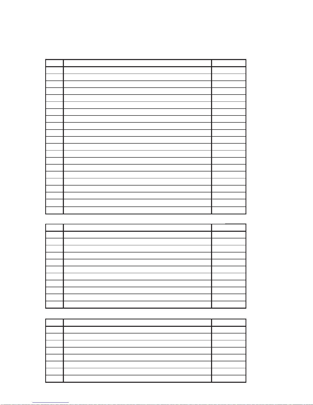
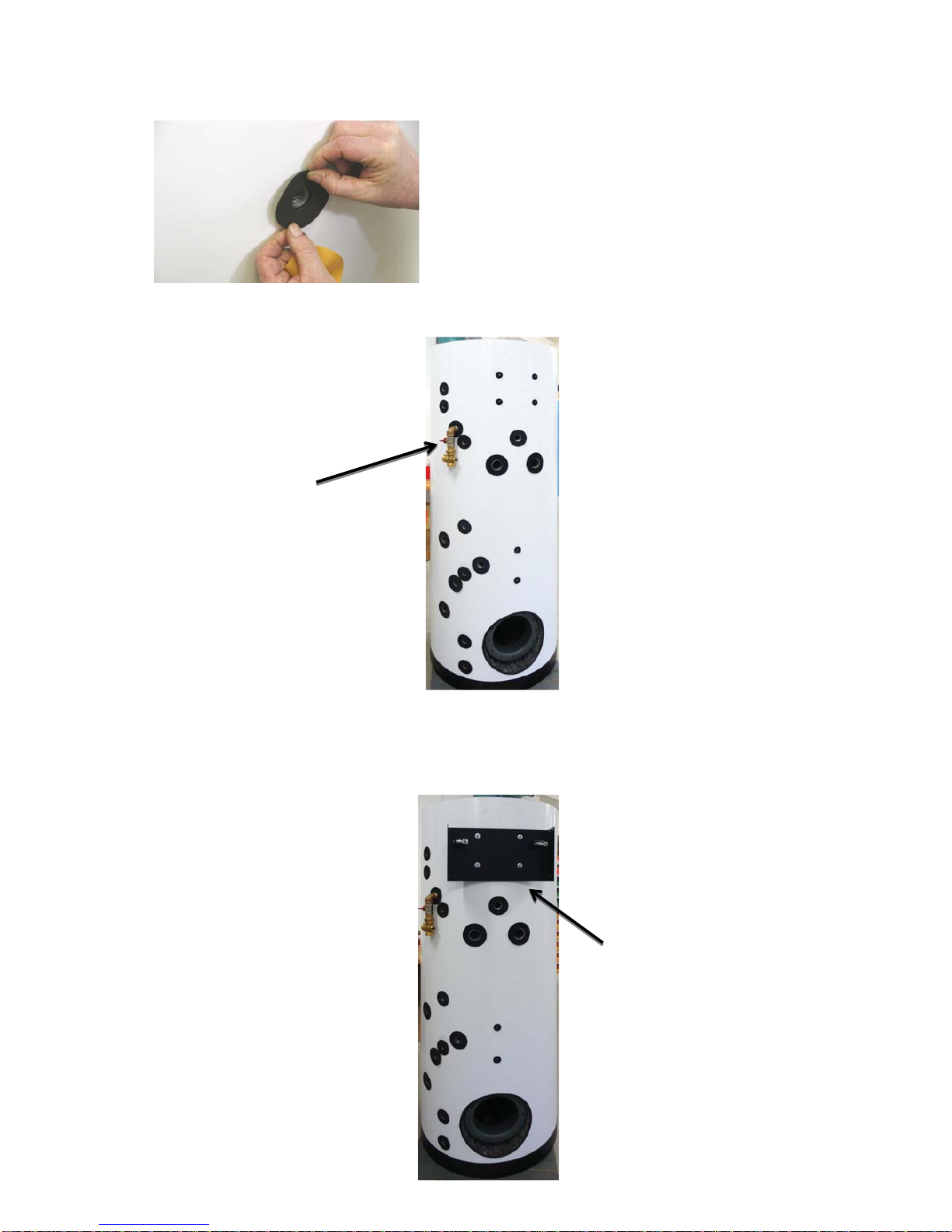
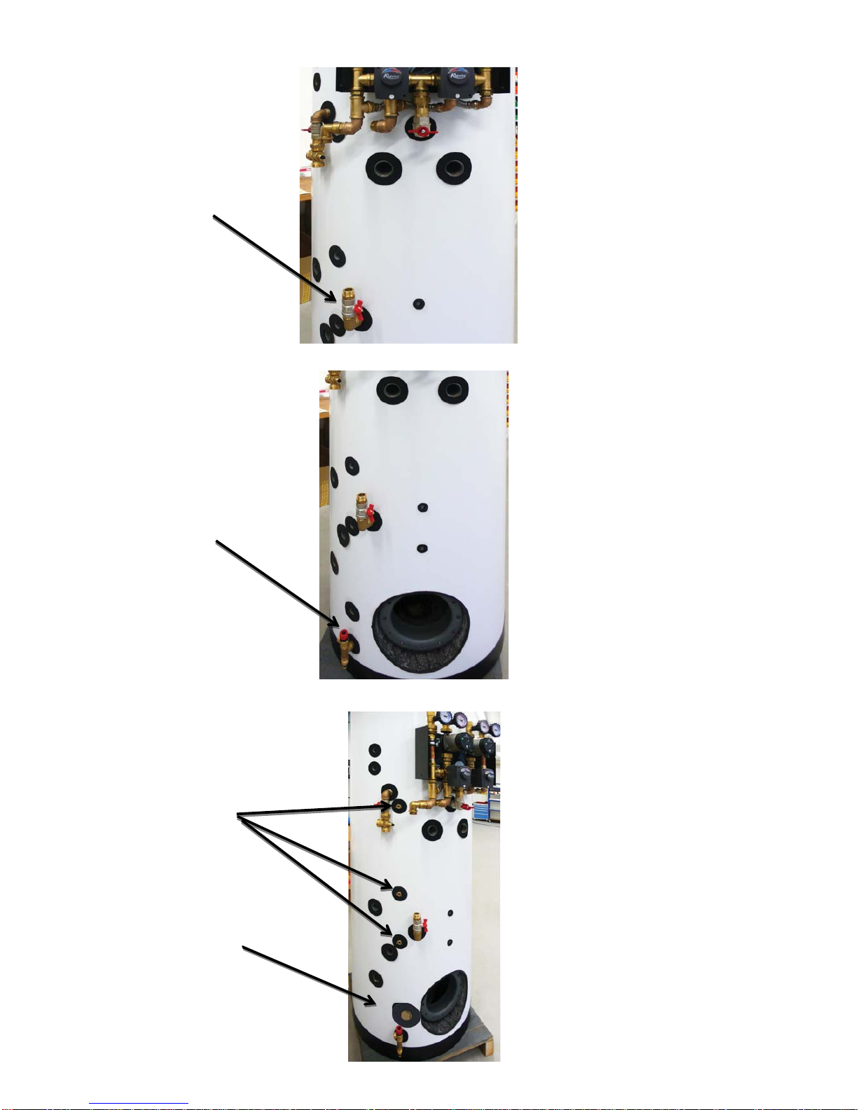
13529 Safety & Drain Valve Assy for VEGA 390 1 pcs
13237 Accessory Kit for LYRA and VEGA 1 pcs
6230 Flange for PS2F tank, d=312, no holes 1 pcs
13485 Kit for connection of assys onto VEGA 390 1 pcs
154 Sheath 7x8-100, 1 sensor, 1/2" 3 pcs
10845 Capillary spring, small, 1/2", stainless steel 3 pcs
12714 Cover for 2-circuit pump station, for 380l Thermal Store 1 pcs
12223 Front insulation for cover for 2-circuit pump station 1 pcs
12721 Top insulation for 2-circuit pump station, 380l 1 pcs
12713 Black knurled screw, M6x1-10 PA 6.6 4 pcs
Code Name Qty
6969 1" hex nipple, MM, thick wall 1 pcs
13481 DN 20 pipe (1" nut) l=1010 mm 1 pcs
13489 DN 20 pipe (1" nut) l=690 mm 1 pcs
13488 DN 25 pipe (5/4" nut) l=490 mm 1 pcs
13484 DN 25 pipe (5/4" nut) l=125 mm 1 pcs
7187 Insulation DNa 35, 13 mm thick (2 m) 1 m
6447 Insulation DNa 28, 13 mm thick (2 m) 2 m
12996 M6x16 stainless steel bolt (hex socket) DIN 912/A2 4 pcs
7853 6.5 washer (large diameter 3d) 8 pcs
9980 1" nut gasket - 18,5x30x2 PTFE 4 pcs
9981 5/4" nut gasket - 25x39x2 PTFE 4 pcs
Code Name Qty
11969 6/4" FF ball valve 1 pcs
7627 6/4“ Hex nipple, MM, thick wall 2 pcs
8757 6/4" T-piece in brass, FFF 1 pcs
8766 Reducing hex nipple 1"x6/4" MM 1 pcs
7049 1" T-piece in brass, FFF 1 pcs
6969 1" Hex nipple, MM, thick wall 1 pcs
7701 Reducing hex nipple, 1“x1/2“, MM, brass 1 pcs
11713 1/2“ drain valve, no handle, with cap 1 pcs
9097 Plug 1/2“ + gasket, brass 1 pcs
12968 - VEGA 390 2 circ.
13485 - Assemblies Connection Kit for VEGA 390
13437 - Expansion Vessel Connection Kit

7 │
MOUNTING INSTRUCTIONS
WARNING! At least 20 °C and 2-3 persons are necessary to mount the insulation. All
threaded connections shall be sealed either with a thread sealant or with the gaskets
included in separate kits.
1. Remove the tank from its pallet and place it to its approximate position, shift the bottom
insulation under the tank.
2. Slide the insulation inserts into the openings for connections.
3. Fit on the insulation and check its proper position towards the sockets prior to final fixing.
Use the jig to close the locks.

│8
4. Peel off the protective foil from the insulation, apply the self-adhesive annuluses around
the openings for connections. From this point on, it is important to stick to the sequence
of installation steps described below!
5. Fit the Zone Valve Assy in from HP, code 13476. Remove the zone valve actuator from the
assembly prior to mounting. Port A of the zone valve shall be oriented upwards.
6. Loosen the clamps, fit the metal sheet against the four pins, code 12710 from Kit code
12224, and fix using 4 screws M6x16 with washers (codes 12996 and 7853) - both these
components are included in the Kit code 13485. Do not forget to place insulation washers
under and on the metal sheet. The single-circuit variant is fitted with the left clamp only.

9 │
7. Fit the Angled Ball Valve Assy, code 12690.
8. Fit the pump station with 4-way mixing valves, code 12224 or 12225. Join it with the earlier
fitted Angled Ball Valve Assy and tighten the clamps.
9. Fit 1” Valve Assy out to h. circuit, code 13479, and 1“ hex nipple, code 6969, from the Kit
13485.

│10
10. Fit the 1” Valve Assy out to h. circuit, code 13497.
11. Fit the Safety & Drain Valve Assy, code 13529, into the sleeve.
12. Fit the sheaths, code 154, into the dedicated sleeves and plug 1/2” with gasket, code 9097.
Plug 1/2“,
code 9097
Stesths,
code 154

11 │
13. Fit the Zone Valve Assy out to HP, code 13477. Remove the zone valve actuator prior
to fitting. Port A of the zone valve shall be oriented upwards.
14. Fit the 1” Elbow Assy out to HP, code 13494.

│12
15. Fit the thermometer, code 10474, from the Kit 13237.
16. Fit the 1” Elbow Assy in from HP, code 13478.

13 │
17. Cut the insulation and slide it onto the pipes from the Kit 13485.
- 1 tube 1” DN 20, 1010 mm long, code 13481, insulation circa 1100 mm long.
- 1 tube 1” DN 20, 690 mm long, code 13489, insulation circa 750 mm long.
- 1 tube 5/4” DN 25, 490 mm long, code 13488, insulation circa 550 mm long.
- 1 tube 5/4” DN 25, 125 mm long, code 13484, insulation circa 200 mm long.
18. Locate the Zone Valve Assy fitted as shown in point 13 and the Elbow Assy fitted as
shown in point 14. Connect these two using the dedicated 5/4” DN 25 pipe, 125 mm long,
code 13484.
19. Locate the Zone Valve Assy fitted as shown in point 5 and the Elbow Assy fitted as shown
in point 16. Connect these two using the dedicated 5/4” pipe, 490 mm long, code 13488.

│14
20. Locate the 1” hex nipple (in the pump station with 4-way mixing valves) fitted as shown
in point 9 and the 1” Valve Assy fitted as shown in point 11. Connect these two using the
dedicated 1” pipe, 690 mm long, code 13489.
21. Locate the 1” hex nipple (in the Zone Valve Assy) fitted as shown in point 13 and the 1”
Elbow Assy fitted as shown in point 9. Connect these two using the dedicated 1” pipe,
1010 mm long, code 13481. Fit the actuators to zone valves.

15 │
22. Fit the automatic air release valve (code 11708) with ball valve (code 11965) and hex
nipple (code 6971), all included in Kit 13237.
23. Push the front insulation onto the pump station with 4-way valves.
24. Connect the terminals of the pumps, push the cables behind the insulation.
25. Fit the plastic cover onto the pump station with 4-way valves and fix it with 4 plastic
screws M6x10 (code 12713).

│16
Completely fitted tank:
Safety high-limit
thermostat for electric
heating elements
(optional part).

17 │
5.2 Connecting heating circuits
1. Return line from Heating Circuit 1 – G1”F
2. Flow to Heating Circuit 1 – G1”F
3. Flow to Heating Circuit 2 – G1”F
4. Return line from Heating Circuit 2 – G1”F
1. Return line from Heating Circuit 1 – G1”F
2. Flow to Heating Circuit 1 – G1”F
5.3 Connecting a solar circuit
This tank can be also connected to a solar
thermal system. An extra flange and a tube heat
exchanger (coil) will be needed, depending on
the output of the solar thermal system.
All connecting pipes between the tank and solar
collectors shall be insulated meticulously.
The solar pump station shall be connected
using M6x16 screws with washers for pins,
see Fig.
1. Inlet from solar collectors – G3/4” M
2. Return line to solar collectors – G3/4” M
143
2
12
As a variant, VEGA can be supplied with
a pump station for one heating circuit only.
12

│18
6 - Installation and Commissioning
Installation shall meet valid rules and may be done by qualified staff only.
Defects caused by improper installation, use or handling are not covered by warranty.
After the tank is installed and connected to an existing heating system, it is recommended to clean
the entire heating system using a suitable cleaning agent, e.g. MR-501/R.
Anti-corrosion protective liquid should be also used, e.g. MR-501/F.
6.1 - Connecting heat sources
The tank shall be placed on the floor, as close to the heat source as possible. Mount the insulation,
see Chapter Mounting insulation onto the tank. Connect heating circuits to the inlets and outlets re-
specting the temperature distribution in the tank. Insulate all the connecting piping.
6.2 - Connecting a solar thermal system
This tank can be also connected to a solar thermal system. An extra flange and a tube heat ex-
changer (coil) will be needed, depending on the output of the solar thermal system. All connecting
pipes between the tank and solar collectors shall be insulated meticulously.
6.3 - Installing a heating element
The Thermal Store can be fitted with two 3-phase electric heating elements with a longer non-heat-
ing end (ETT-C or ETT-L), 6 kW max. output each, or with two single-phase electric heating ele-
ments with a longer non-heating end (ETT-M), 3 kW max. output each. They can be wired directly to
the mains (heating elements equipped with own thermostat), or via a Controller for the entire heating
system.
All el. heating elements shall be installed together with a safety temperature limiter.
An el. heating element shall be wired by qualified staff only.
6.4 - Connecting sanitary water piping
DHW piping shall be done according to valid rules. Installation of a pressure reducing valve to the
tank inlet is recommended. If the pressure from water mains exceeds 6 bar, a reducing valve is
necessary. Should the water be too hard, install a water softener before the tank. In case the water
contains mechanical impurities, install a strainer.
6.5 - Commissioning
The tank shall be filled up together with the heating system, respecting valid standards and rules.
In order to minimize corrosion, special additives for heating systems should be used. The quality of
heating water depends on the quality of filling water at commissioning, on the top-up water and on
the frequency of topping up. This has a strong influence on the lifetime of heating systems. Poor
quality of heating water may cause problems like corrosion or incrustation, esp. on heat transfer
surfaces.
Hot water quality must meet the conditions shown in the Table of limit values for total dis-
solved solids in hot water on this page.
Fill the heating circuits with the appropriate fluids and air-bleed the entire system. Check all connec-
tions for leaks and verify the system pressure. Set the heating controller in compliance with the docu-
mentation and manufacturer’s recommendations. Check regularly proper function of all control and
adjusting elements.
Table of limit values for total dissolved solids in hot water
Description pH Total dissolved
solids (TDS) Ca Chlorides Mg Na Fe
Max. value 6,5 - 9,5 600 mg/l 40 mg/l 100 mg/l 20 mg/l 200 mg/l 0,2 mg/l

19 │
7 - Mounting insulation onto the tank
Product description
Thermal insulation is a part of Thermal Stores that prevents heat loss. For these Thermal Store
models, the insulation is delivered separated for easier handling and needs to be mounted on the
spot. The insulation consists of 3 layers: the first one is soft insulation fitting tightly on the tank; the
second, main layer, features thermal conductivity l=0.032 W/m.K; the third layer is a hard, glossy
washable surface. The total insulation thickness is 100 mm.
Caution
Insulation mounting shall be done in two or three persons, depending on its size. It must be done
at temperatures of at least 20 °C. If this cannot be respected, the insulation shall be pre-warmed
in another room to at least 20 °C. It is impossible to install insulation under lower temperature,
there is a risk of damage. Do not use any tools for installation.
Keep away from open fire.
Warranty on insulation
□Warranty shall become null and void if:
○the procedure described in the Installation Manual was not respected,
○the product was used for other purposes than intended.
□Warranty does not cover:
○usual wear and tear,
○damage caused by fire, water, electricity or a natural disaster,
○defects caused by failure to use the product in compliance with its intended purpose,
by improper use and insufficient maintenance,
○defects caused by mechanical damage to the product,
○defects caused by tampering or incompetent repair.
8 - Maintenance
If the tank is fitted with a heating element, disconnect it from the mains first. Clean the exterior of
the tank with a soft cloth and a mild detergent. Never use abrasive cleaners or solvents
Check all connections for leaks.
9 - Disposal
Packaging shall be disposed of in compliance with the valid rules. When the product reaches the
end of its life, it shall not be disposed of as household waste. It shall be dropped off at a Local
Waste Recycling Center. Insulation shall be recycled as plastic and the steel vessel as scrap iron.
10 - Warranty
This product is covered by warranty under the conditions listed in this Manual and in compliance
with the Warranty Certificate. A Warranty Certificate is an integral part of this Thermal Store scope
of supply.

0
4
/
2
0
1
6
REGULUS spol. s r.o.
Do Koutů1897/3 http://www.regulus.eu
CZECH REPUBLIC
Table of contents
Other Regulus Solar Panel manuals
Popular Solar Panel manuals by other brands

Floe
Floe 511-01354-00 Assembly instructions

ACOPOWER
ACOPOWER HY-PLK-100WPX20A manual

Solar Technology International
Solar Technology International PV Logic STP005 user manual

Grape Solar
Grape Solar GS-300-KIT Quick connect guide

Perception
Perception SOL160W-FS user manual

REC
REC REC235 Series installation manual