│8
REGULUS - RDC - www.regulus.eu
6 - Installation and Commissioning
Installation must meet valid rules and may be done by qualied staff only. The tank shall be placed on the
oor, as close to the heat source as possible.
Warning: Defects caused by improper installation, use or handling are not covered by warranty.
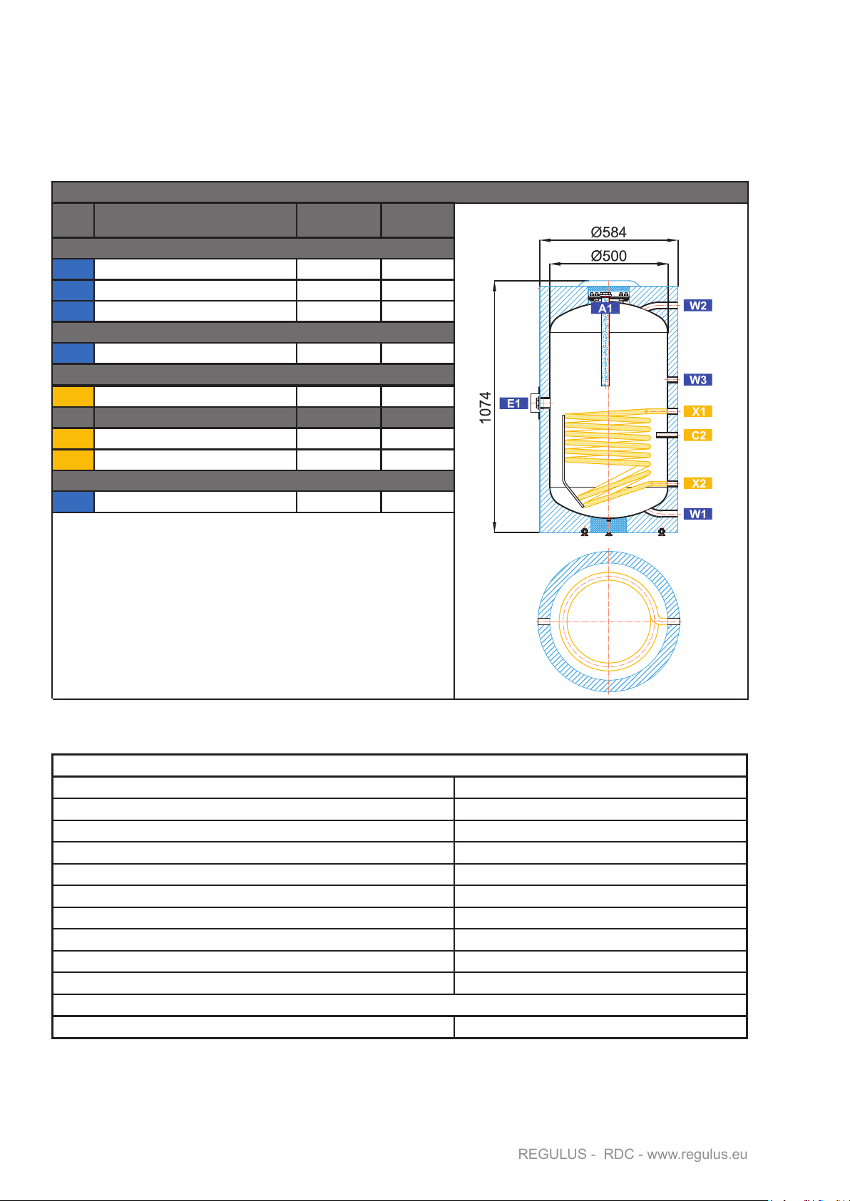
6.1 - Connection to heat sources
Connect the heating circuits to the inlet to and outlet from heating coil using G 3/4” nipples.
6.2 - Connection to a solar system
The tank can be used with a solar system. In such a case, the inlet for hot heat-carrying liquid coming from the
solar system shall be connected to the G 3/4” upper sleeve of the heating coil and the lower outlet to the return
piping to the solar system. Insulate all the piping between the tank and the solar system.
6.3 - Heating rod installation
The G 6/4“ side sleeve is designed to accommodate an electric heating rod. Heating rods of output up to
6 kW can be used (depending on the tank diameter and rod length), connected either directly to the mains
(thermostat-equipped rods), or to a heating system controller. The installation may be done by qualied staff
only.
Warning: All electric heating elements shall be protected by a safety thermostat.
6.4 - Connection to water mains
DHW piping shall be done according to valid rules. G 3/4” threaded couplers are used to connect the tank to
a cold water inlet and hot water outlet. A 6bar safety valve shall be installed at the cold water inlet, installation
of a reducing valve is recommended. If the pressure from water mains exceeds 6 bar, a reducing valve is
necessary. In order to prevent water loss, an expansion tank should be installed at the cold water inlet as well
(8l volume for RDC 160, RDC 200 and RDC 250, 12l volume for RDC 300).
Should the water be too hard, install a water softener before the tank. In case the water contains mechanical
impurities, install a strainer.
A suitable thermostatic mixing valve should be installed at the hot-water outlet from the tank, preventing too
hot water from entering the taps.
Install a drain valve to the lowest point of the tank.
Complete DHW piping shall be properly insulated.
6.5 - Electronic anode rod installation
A so called electronic anode rod can be used instead of the magnesium one for RDC tanks. When installing
an electronic anode, the magnesium anode rod in the lower ange shall be removed. Its principle advantage
is that it doesn’t need to be taken out for function check. In this case, just visual check of the electronic anode
indication lamp is sufcient.
Kits for RDC storage water heaters.
Should an electronic anode rod or ran electric heating rod be installed, an interconnection shall be done, i.e.
the metal mantle of the storage tank shall be wired to the protective neutral.
6.6 - Commissioning
Fill the heating circuit with the appropriate uid and air-bleed the entire system.
Fill the tank with cold water following this sequence:
- open the shut-off valve at the tank inlet
- open the hot water tap/outlet point, as soon as hot water starts owing, lling is complete; close the
tap
- check all connections for leaks and the system pressure
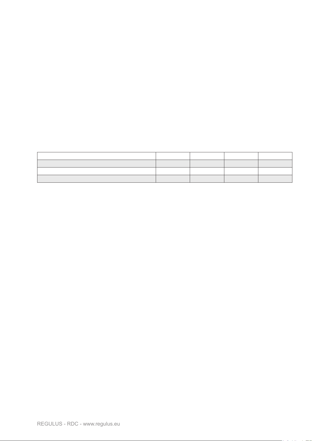
For tanks El. Anode Kit code - replacement Anode rod length
RDC 160 9173 350 (200/150)
RDC 200, RDC 250 9174 500 (350/150)
RDC 300 17378 500 (350/150) + 350 (200/150)


 null")
 null")


 Operation and maintenance instructions")