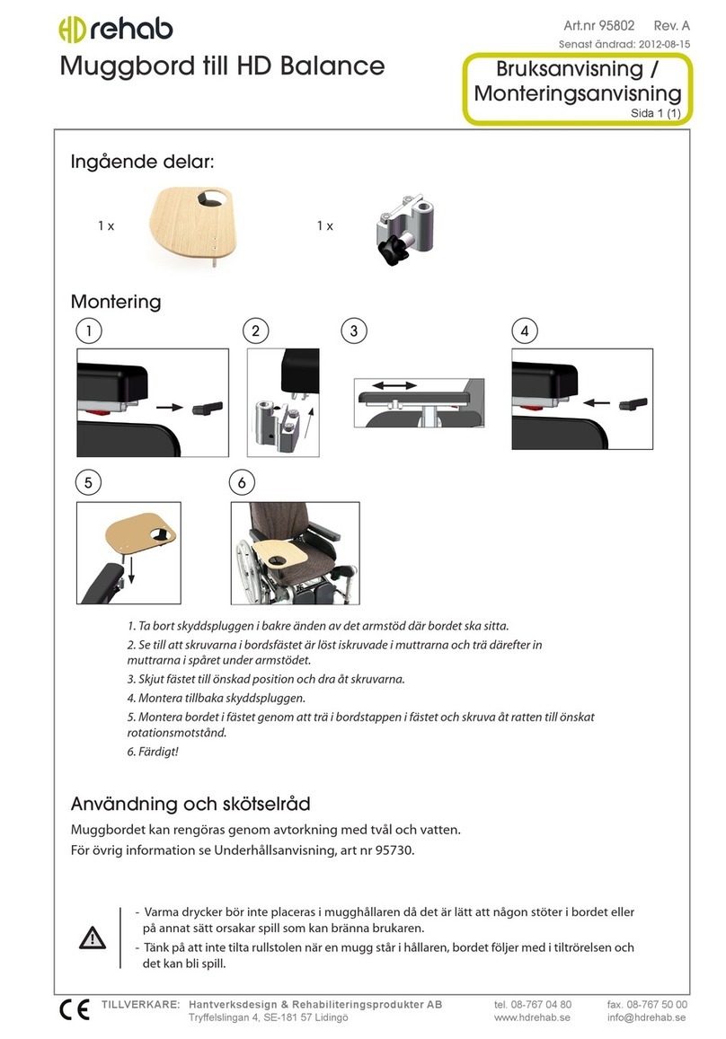
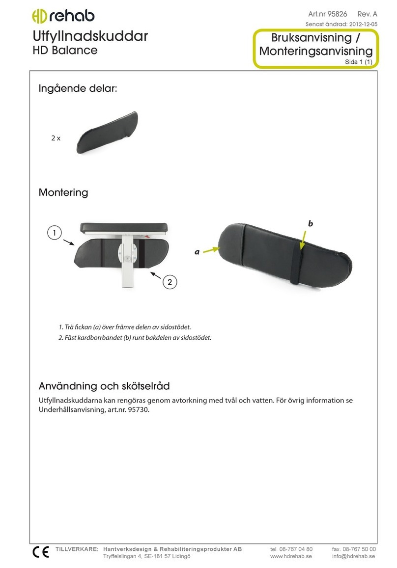
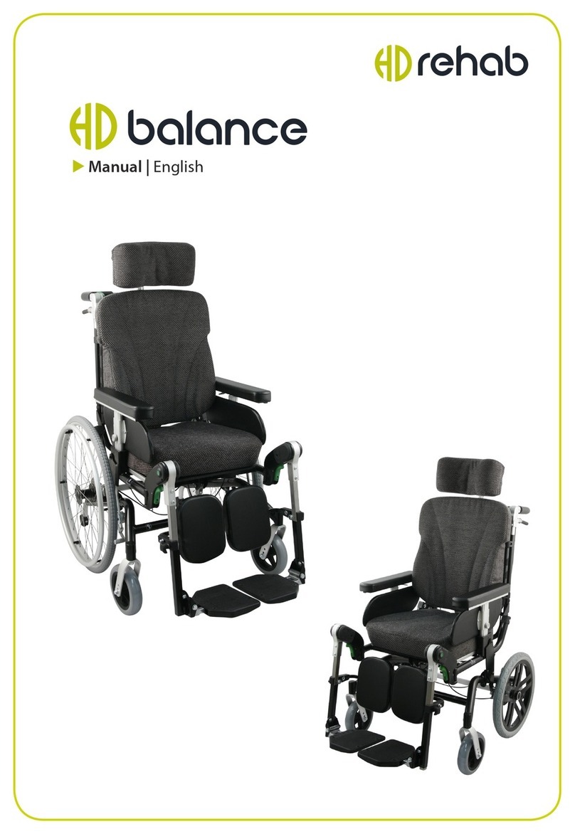
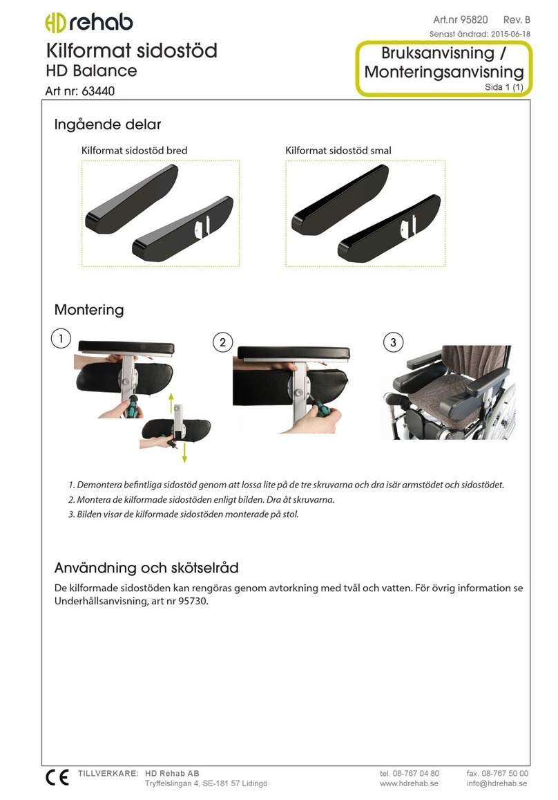
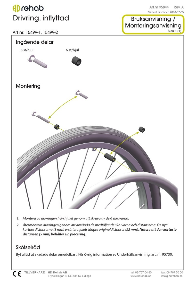
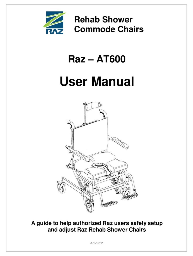
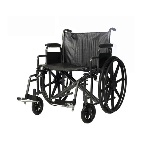
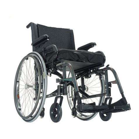
Rehab HD Balance Series Manual

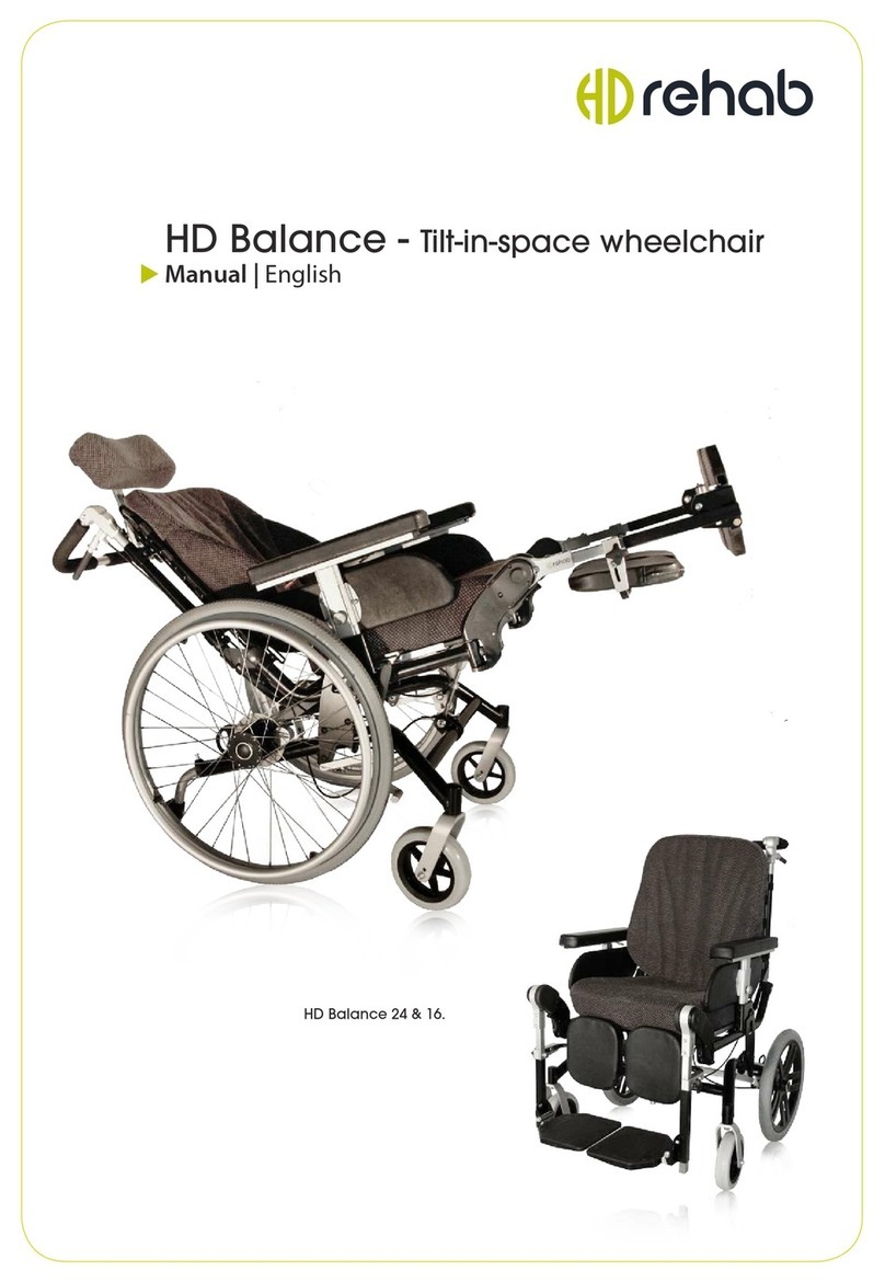
HD Balance - Comfort Wheelchair
Technical Information | English
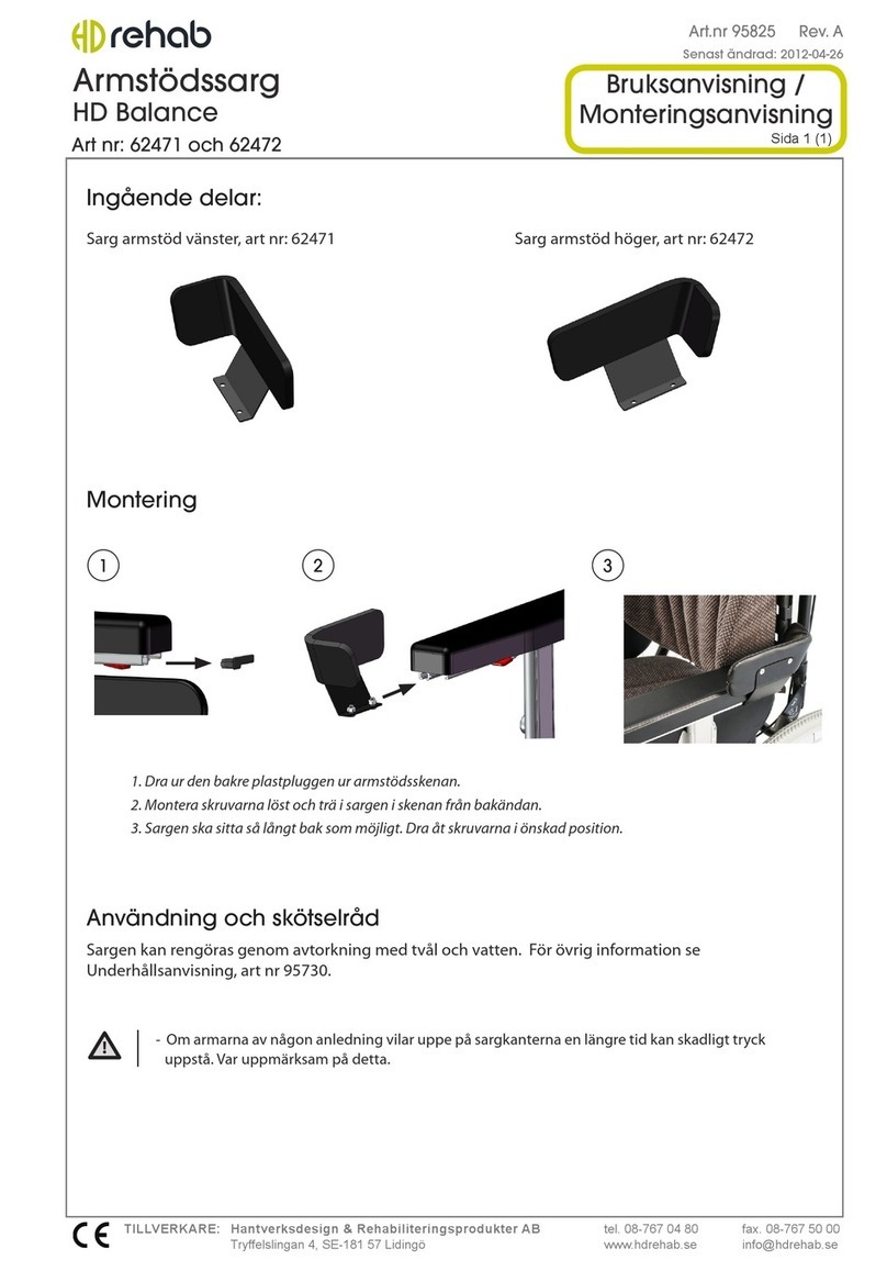
HD Balance 24 & 16.

© 2012 HANTVERKSDESIGN & REHABILITERINGSPRODUKTER AB
WE MANUFACTURE QUALITY OF LIFE
HD Rehab helps people achieve an improved quality of life. Our products make the
lives of users, their families, and their caregivers easier, safer, and more comfortable.
HD Rehab offers aids for people living with disability. We have designed, developed, and
manufactured comfort wheelchairs for over 40 years. We never compromise when it comes to
quality. Precision, safety for users and caregivers, function, and comfort are important bywords
for us. We are condent that whatever other wheelchairs you try, you will be able to feel the
difference.
GLAD TO BE FLEXIBLE
Whether you are a user, a family member, a technician ,or a caregiver, we welcome your
requests and opinions. Our designers and developers work closely with each other and with
the production team at our Lidingö base. Our skilled employees use their specialist knowledge,
experience, and creativity to nd solutions for the unique needs of each individual user.

3
HD BALANCE | Technical Information
TABLE OF CONTENTS
1 General Information 4
1.1 Important documents 4
1.2 Lubricants and Threadlockers 4
1.3 Finishes 4
2. Chassis Construction 5
2.1 Chassis configuration options 5
2.2 Change of back frame 5
2.3 Change of seat frame 5
2.4 Change of balancing plates 6
2.5 Enabling increased tilt 7
2.6 Change of tilt rod and tilt lock 7
2.7 Change from gas spring to rod for
fixed back angle 8
2.8 Replacing a defetive gas spring 8
2.9 Drive wheel and cross tube positions 8
3. Construction of Various Components 10
3.1 Disc brake system 10
3.1.1 Adjust of disc brakes 10
3.1.2 Change of cable 10
3.1.3 Change of brake pads and/or brake disc 10
3.2 Tire brakes 11
3.2.1 Assembly 11
3.2.2 Adjustment 11
3.3 Seat tilt - Controls and tilt lock 11
3.3.1 Adjustment of cable 11
3.3.2 Change of cables and controls 11
3.3.3 Change of cable alone 12
3.4 Recline - Controls and Gas spring 12
3.4.1 Adjustment of cable 12
3.4.2 Change/assembly of cable and controls 13
3.4.3 Fixed back angle 13
3.5 Drive wheel attachment 13
3.5.1 Change of wheel axle 13
3.5.2 Wheel axle quick release 13
3.6 Castors 13
3.6.1 Change of castor fork 13
3.6.2 Change of castor 13
3.7 Armrest 14
3.7.1 Height adjustment mechanism 14
3.7.2 Depth adjustment mechanism 14
3.7.3 Change of armrest pad 14
3.8 Leg rest 14
3.8.1 Knee joint attachment 14
3.8.2 Change of knee joint inner pad 15
3.8.3 Change of knee joint outer pad 15
3.8.4 Change of leg rest tube 15
4. Accessory Information 15
4.1 Electrical actuator 15
5. Overview Diagram 16
Document information 16

4HD BALANCE | Technical Information
1 General information
HD Balance is a comfort wheelchair intended for users who need excellent support and comfort
in their daily routine. The back and seat can tilt in different positions to give the user a variety of
seating options for activity and rest.
HD Balance is a Medical Device Class 1 per the Swedish Medical Products Agency.
1.1 Important Documents
The following documents are good to have available when working with an HD Balance:
95431-1 Information about custom-made products
Information about regulations for adaptations and modications of medical
products.
95707-1 Risk information about special congurations and accessories for HD Balance
Information about increased risks when using certain special congurations
and accessories.
95758-1 Reference table - balancing modes
Information on the consequences of different balancing congurations. E.g. if
restrictions exist, or if further modications to the wheelchair are required.
95759-1 Reference table balance congurations
Table of which balancing congurations are allowed on different models and
with different designs.
95764-1 Labeling - HD Balance
Contains information about which labels are to be found on an HD Balance.
95730-1 Maintenance Schedule
1.2 Lubricants and threadlockers
The following table details recommended lubricants and threadlockers:
Usage area Lubricant /Threadlocker type Product used by HD Rehab
General lubrication of sliding
surfaces etc.
Synthetic food grade grease Fuchs Cassida EPS 2
Vendor: Ikaros AB
Tilt lock / tilt rod
Wheel attachments (internal)
Thin long-lasting synthetic
lubricating oil
Zee Zyynth Oil
Vendor: Chemlight Systems AB
Knee joint (internal) Penetrating oil with good
adhesive properties, water
repellant
LUBRI 40
Vendor: Chemlight Systems AB
Locking of screws, permanent
e.g. wheel axle pin
High strength threadlocker Loctite 2700
Locking of screws to crossbars etc
that may be removed for repairs
Medium strength threadlocker Loctite 2400
1.3 Finishes
The following nishes are used on HD Balance:
Powdercoat painting. Colour code RAL 9005 Black, gloss 40.
Anodizing.
Nitrocarburizing.

5
HD BALANCE | Technical Information
2. Chassis Construction
The HD Balance chassis is constructed of three interacting frames; wheel frame, seat frame, and
back frame. These are attached to each other at a number of points such that desired geometry
for balance, recline, and seat tilt can be achieved. The wheel frame and seat frame are connected
by balance plates. The balance plates are critical to the characteristics of the wheelchair.
The two models, 16 and 24, have identical chassis with the exception of the wheel frame, where
the plates for wheel attachment have different designs.
2.1 Chassis conguration options
The HD Balance chassis can be modied to change the wheelchair characteristics. The standard
conguration is the reference point for any given data in terms of characteristics, function,
measurements, and tests against existing standards. Changes to the chassis conguration come
with both positive and negative consequences. Therefore the standard conguration should be
used wherever possible.
The following modications can be made:
- Change of balancing plates. Provides raised seat height, lowered seat height, or moving
the balance point forward or backward. Described in section 2.4.
- Lengthened seat frame. Provides increased seat depth. Must be selected with initial
wheelchair order, cannot be changed after assembly.
- Increased / Limited tilt. Described in section 2.5.
- Change of tilt rod. Eects tilt range per document 95758-1. Described in section 2.6.
- Change to rod in place of gas spring. Provides a xed back angle between 90 and105
degrees. Described in section 2.7.
- Moving wheel mounting point 50 mm backward. Makes the wheelchair more stable but
with somewhat poorer handling. Described in section 2.9.
2.2 Change of back frame
1. Remove the push handle by pulling it competely out of the back
frame. Be careful with the cables!
2. Remove the back cushion and disassemble back system (Flexi-
back or Fixed back).
3. Release the rear bracket of the gas spring by pulling out the pin
so that the gas spring can be gently removed.
4. Remove the retaining rings on the inside of the back system
attachment points (A, g1). Tap the pins so that the back frame
can be lifted o. NOTE! It is not necessary to remove the pins
completely in order to release the back frame.
5. Remove the back frame and replace it with the new frame.
6. Assemble the new frame by repeating the same steps in reverse
order. Be careful not to damage the retaining rings, replace
them with new rings if necessary!
2.3 Change of seat frame
1. Remove the back frame per section 2.2 steps 1-4.
2. Remove seat cushion, seat board, leg rests and armrests.
3. Remove tilt rod and gas spring per section 2.6 steps 1-5.
4. Remove the screws from both balance plates (A, g 2).
5. Carefully press one balance plate outwards (B) so that
the seat frame can be lifted o. Be careful when the seat
frame comes free as there can be a pinching hazard and
cables can be damaged.
A
Fig 1
B
Fig 2
A

6HD BALANCE | Technical Information
6. Change out the seat frame and re-attach by reversing the
above steps. NOTE! Refer to Figure 3 and be sure that the
bushings (C) that sit between the balance plate (B) and
seat frame (D) are seated in the correct direction! The
longer side must face outwards.
The bolt (E) should be tightened rmly but with moderate
force. After driving the bolt into the lock nut (F) check that
the armrest bracket is working properly. If there is any
doubt the nut should be replaced by lifting the armrest
out of the frame (G). Take care that the inner washer (H)
does not fall out.
Check that the seat frame turns easily between the
balance plates.
2.4 Change of balancing plates
When changing the balancing plates it must always be ensured that the wheelchair conguration
follows the guidelines from HD Rehab. The congurations that are approved are detailed in
document 95759-1. Commentary on limitations and other adjustments that must be made is
found in document 95758-1. Risk information is given in document 95707-1.
NOTE! The balancing plates cannot be changed if the wheelchair is equipped with electric tilt.
Always read this before commencing work and have it at hand during the process!
PARTS INCLUDED: Balancing plates, screws for movement of cross tubes (as required), new tilt rod (as required)
Change and assembly of balancing plates is done as follows:
1. Remove wheel and take o brake cable from wheel mount, per section 3.1.2 steps 1-3.
2. Remove armrest and back and seat cushions, fold back into transport position.
3. Loosen the tilt rod as follows:
- Unscrew the lower stop ring and remove it.
- Tilt the wheelchair backwards until the tilt rod draws completely out.
Be careful with seat and back frames when the tilt rod is released as they
then hang freely in the balance plates and can be a pinching risk!
4. Take apart the tilt lock per section 2.6 steps 7-8.
5. Remove the screws (A, gures 4 and 5) that hold the seat frame in place.
6. With a rm grip on the seat and back frame, carefully press one balance
plate outwards so that the seat frame can be removed from the
suspension. Lift o the seat and back system. Be careful with the cables!
7. Switch to the desired balancing plates by removing the screws (B, g 5),
changing plates, and attaching again with the same screws.
C
G
D
E
FB
Fig 3
H
Standard Raised 5cm Lowered 3cm Moved forward 3cm
Moved backward 3cm
A
Fig 4
A
B
Fig 5

7
HD BALANCE | Technical Information
8. Change the tilt rod per the instructions in section 2.6 (if required by the desired wheelchair conguration).
Refer to document 95758-1.
9. Move the rear cross tube to its new position per the instructions in section 2.9 (if required by the desired
wheelchair conguration). Refer to document 95758-1.
10. Reassemble the seat and back frame unit in the balancing plates and tighten the screws, per section 2.2
step 6 and 2.3 step 6.
11. Reassemble tilt lock. Check that retaining ring is in good condition and replace with new ring if necessary.
12. Tilt the seat back and t the tilt rod into the tilt lock. Assemble the stop ring in the correct position for the
desired wheelchair conguration. Refer to document 95758-1.
13. Fold the back up to the normal position and reassemble the gas spring with the pin through
the rear part. Ensure the pin passes through both plates of the mount on the back frame.
14. Reassemble brake cables and check braking function. Put the cushions and armrests in place.
2.5 Enabling increased tilt
Icreased forward tilt to -5 degrees (in some cases less depending
on conguration) and increased backward tilt to 30 degrees can
be achieved by moving the stop rings on the tilt rod. The tilt
rod may also need to be changed to a longer version (refer to
document 95758-1).
Follow these steps to move the stop rings:
1. Check that the tilt lock has locked the tilt rod in a set position rather
than the tilt rod sitting between two positions.
2. Loosen the set screw (A, g 6) that holds the stop ring in position.
3. Move the stop ring to the desired position. Read carefully
in 95758-1 which position is correct for dierent wheelchair
congurations.Note that if the stop ring is moved up from the
lowest hole a screw (C) must be placed in that hole and the set screw
(A) must be replaced by a shorter version (B), and vice versa.
4. If the tilt is increased forward (under 0 degrees) or backward (over
20 degrees) a warning sticker must be attached per document
95764-1 ”Labeling, HD Balance”.
5. Always check the tilt lock is functioning correctly before using the
wheelchair!
2.6 Change of tilt rod and tilt lock
The tilt lock controls the position of the tilt rod depending on the desired seat tilt. The green
tilt lever on the push bar releases the tilt lock via a cable. Follow these steps to change out the
tilt lock and/or tilt rod:
1. Remove leg rests, armrests, seat and back cushions from wheelchair.
2. Fold the back frame into the transport position by releasing the rear
connection of the gas spring.
3. Remove the lower stop ring (tilt the wheelchair backwards to access).
4. Move the seat plate backward and remove one of the retaining rings
that holds the tilt rod and the gas spring (A, g 7). Hold the gas spring and
knock out the pin incrementally such that only the gas spring comes free.
Set aside the gas spring. Take hold of the seat frame and knock the pin out
completely so that the tilt rod comes free.
5. Swing out the seat frame without damaging the cables.
6. Change out the tilt rod and reassemble by reversing the above steps.
B
C
A
Fig 6
Fig 7
A
B

8HD BALANCE | Technical Information
NOTE! The tilt rod must be properly locked in the tilt lock when the fastening
fork of the tilt rod is placed between the plates on the seat frame. If the
fork is twisted and will not pass between the holes, the nut under the fork
must be loosened so that the angle can be adjusted (Refer to Spart Parts
document 95740-1, page A6.1 item 16). Check that the retaining ring is not
damaged and replace if necessary. Pause the reassembly at this point if the
tilt lock will also be changed.
If the tilt lock (B, g 7) is to be changed (requires cable change):
7. Remove the green control lever and housing from the push bar.
8. Remove retaining ring (C, g 8) from tilt lock and pull it out of the bracket.
9. Place the new tilt lock in the bracket and secure with the retaining ring.
Check that the retaining ring is in good condition. Note! The tapped hole
where the wire will be attached must be above the cross tube.
10. Assemble a new cable package per the instructions in section 3.3.2 steps
5-9, or assemble just a new cable per section 3.3.3.
2.7 Change from gas spring to rod for xed back angle
1. Remove cushions, leg rests, and seat plate.
2. Disassemble the back tilt lever (grey) from the push bar.
3. Release the rear connection of the gas spring by pulling out the peg and
folding the back frame forwards. Be carefeul as the back frame can fall
down when the peg is pulled out.
4. Remove the retaining ring from the pin (A, g 9) that holds the front of
the tilt rod and the gas spring. Carefully knock out the pin such that the
tilt rod and gas spring come free but the pin remains partially engaged
and holds the seat frame in place.
5. Replace the gas spring and tilt rod with the desired conguration.
6. Reassemble by reversing the above steps and adjust the cable as
necessary per section 3.4.1.
2.8 Replacing a defective gas spring
1. Remove cushions, leg rests, and seat plate.
2. Release the rear connection of the gas spring by pulling out the peg and
folding the back frame forwards. Be carefeul as the back frame can fall
down when the peg is pulled out.
3. Use a wrench to relese the gas spring (A, g 10) and replace it. Be careful
that all components remain in their correct orientations.
4. Reassemble the back and test that gas spring is functioning correctly.
2.9 Drive wheel and Cross tube positions
The wheel frame cross tube (A, g 11) has three possible positions.
The position must sometimes be changed depending on the chair
conguration or use of certain accessories.
The wheel mount unit has two attachment points with 50 mm
spacing to allow for variation in the wheel base length. The forward
poistion is the standard conguration.
For easier assembly screws can be driven through the large hole in
the disc brake. Be careful when assembling not to damage the disc.
Fig 8
C
Fig 9
A
Fig 10
A
Fig 11
A

9
HD BALANCE | Technical Information
In some positions the cross tube is assembled “through” the wheel mount and in others to
the side, as detailed in document 95758-1. Different screw lengths are used for the different
variations. Be careful that the correct screws are used!
The following gures show which type of screws should be used for each mounting alternative.
Note that locking nuts are used for the screws that are not driven into the cross tube, and medium
strength threadlocker (such as Loctite 2400) for the screws that are driven into the cross tube.
Wheel position: FRONT Wheel position: REAR
Cross tube position: FRONT Cross tube position: FRONT
Wheel position: FRONT Wheel position: REAR
Cross tube position: REAR UPPER Cross tube position: REAR UPPER
Wheel position: FRONT Wheel position: REAR
Cross tube position: REAR LOWER Cross tube position: REAR LOWER
MC6S M8x40
With M8 lock nut
MC6S M8x50 MLC6S M8x25
Cross tube
position

10 HD BALANCE | Technical Information
3. Construction of Various Components
3.1 Disc brake system
The disc brake system (g 12) consists of a disc (g 16) that
attaches to the drive wheel. A caliper (J, g 16) pushes
against the disc when activated by a brake piston (L, g
17). This is controlled by a lever (g 14) via a cable that is
attached to a turntable (D, g 13) which moves the piston.
The cable is of xed length with nipple connections at both
ends.
3.1.1 Adjustment of disc brakes
The brakes are adjusted by moving the cap (A, g 13).
Loosen the nut (B) and screw the sleeve out for more
braking force, in for less braking force. Tighten the nut
(B) after the adjustment. NOTE! Handle sleeve (E) with
care! NOTE! The brakes must always be adjusted such that
the braking force is correct with the braking levers in the
parking position. Verify!
3.1.2 Change of cable
Damaged cables must be replaced immediately! Follow these steps:
1. Remove the wheel and completely unscrew the wire length adjustment cap (A).
2. Remove the sleeve from the plate by unscrewing the nut (C) and threading it out of the slot.
3. Release the end of the wire from the turntable (D).
4. Unscrew the wire attachment (E) from the push bar and thread the end of the wire out of the
braking lever as seen in gure 14.
5. Assemble the new cable by reversing the above steps and adjust per section 3.1.1.
6. The brake cable (F, g 15) is attached by a clip (G) below the back
mounting plate. Figure 15 also shows how the clip (H) for the tilt-/
recline cable (I) should be placed and how the two cables run in relation
to each other. If a tiltable push bar is used the clips should switch places
with each other. The brake cables should then also run behind the tilt-/
recline cable as in gure 15.
3.1.3 Change of brake pads and/or brake disc
Worn or damaged brake pads or brake discs are
changed as follows (see spare parts list for details):
1. Take o the wheel and unscrew the caliper (J, g 16).
2. Remove the retaining ring (K) with correct pliers and
remove disc. Note that there is a plastic washer between
the disc and the wheel hub.
3. Now the brake piston (L, g 17), disc, and caliper can be
changed out for new parts.
If lubricating, be careful that no lubrication gets on the disc or
the caliper. NOTE! The caliper can be cleaned but must remain
completly at to function correctly.
Fig 12
E
A B
CD
Fig 13
I
F
G
H
Fig 15
Fig 14
E
Fig 16
J
K

11
HD BALANCE | Technical Information
4. Reassemble by reversing the above steps. Check the
retaining ring (K, g 16) and replace if damaged.
5. Check brake function and adjust cables as necessary per
section 3.1.1.
3.2 Tire brakes
Tire brakes are always equipped on HD Balance 24, but can also be assembled to HD Balance 16.
The brake lever is different depending on the model and thus brake units cannot be interchanged.
3.2.1 Assembly
1. Attach the brake unit to the brake bar (A, g 18) by tightening the nut (B).
2. Check that the desired braking force is achieved. Adjust as necessary.
Note! For assembly on HD Balance 16 the brake bar must rst be attached to
the wheel frame.
3.2.2 Adjusment
Adjust the braking force by loosening the nut (B, g 18) and moving
the braking unit along the beam (A) until the desired braking force
is reached.
3.3 Seat tilt - Controls and tilt lock
The seat tilt is controlled by the green lever on the right hand side of the push bar. The lever
moves a wire inside a cable, which releases the tilt lock on the front cross tube (g 19).
3.3.1 Adjustment of cable
The cable is adjusted by a sleeve (A, g 20) on the tilt lock, as follows:
1. Check that the tilt lock has locked the tilt rod in a set position rather
than the tilt rod sitting between two positions.
2. Loosen the nut (B) and screw the sleeve in all the way so that the wire is
as slack as possible.
3. Note that there now is some play in the controls such that the rst part
of the movement does not move the cable housing in the sleeve (A).
4. Screw in sleeve (A) so that the gap is almost gone and secure with nut
(B). The tilt rod (C) should not move during the adjustment.
5. Check that the tilt lock locks and releases the tilt rod properly and that it
moves smoothly. Lubricate as required.
NOTE! When the controls are moved the cable housing should rst be
pushed into the sleeve (A) ~2mm and compress the internal spring lock
pin before starting to open. See spart parts list for details.
3.3.2 Change of cables and controls
Change of one or both cables and controls can be done
concurrently.To change just one cable see section 3.3.3. Follow
these steps to change both cables and controls:
1. Check that the tilt lock has locked the tilt rod in a set position rather
than the tilt rod sitting between two positions.
2. Unscrew the tilt control lever (green) from the push bar.
3. Loosen the nut (B) and screw the sleeve in all the way so that the wire is
as slack as possible.
Fig 17
L
Fig 18
A
B
Fig 19
Fig 20
A
B
C
E

12 HD BALANCE | Technical Information
4. Loosen the set screw (C, g 20) that holds the wire in the tilt lock and
pull the wire out. The set screw should be screwed out enough that the
new wire can easily be threaded in.
5. Change cable-control package and mount the controls on the right side
of the push bar.
6. Thread the cable inside the back frame and under the seat to the tilt
lock. There it threads through the sleeve (A, g 20). Note that a spring
(D, g 21) must rst be t over the wire! Be careful to not fray the wire!
7. Pull in the end to put some tension in the wire and screw in the set screw
rmly, using threadlocker.
8. Clip o the end of the wire so that approx 2-3mm remains outside the
pin and put a dab of silicon or hot glue (E, g 20) on the end of the wire
as protection against the sharpness.
9. Adjust the cable per section 3.3.1.
3.3.3 Change of cable alone
When changing a cable the following applies for both recline and tilt. The lower end of the cable
is handled per section 3.3.2 for the tilt cable, or section 3.4.1 for the recline cable. The cable is
separated from the controls as follows:
1. Unscrew the wire sleeve (A, g 22) from the contol bracket.
2. Unscrew the screw that holds the lever (B, g 22).
3. Pull the lever o the control bracket (g 23).
4. Pry the wire out of the metal arm (C, g 24).
5. Assemble the new cable by reversing the above steps.
3.4 Recline - Controls and Gas Spring
Back recline is controlled by the grey control lever on the left side of the push bar. The control
lever is attached to a cable which moves a pin, which in turn releases the gas spring.
3.4.1 Adjustment of cable
The cable is adjusted by a sleeve (A, g 25) by the gas spring.
Follow these steps:
1. Check that the cable is in good condition and that the sleeve at
the control lever is fully screwed in.
2. Loosen the nut (B) and screw the sleeve (A) fully in so that the wire
is as slack as possible.
3. Note that there now is some play in the controls such that the rst
part of the movement does not have any eect.
4. Screw in sleeve (A) so that the gap is almost gone and then secure
with nut (B).
5. Check that the recline is functioning properly and that the cable is
not tense in the locked position. The pin (C) must travel all the way
back in its track when the control lever is released.
Fig 21
D
Fig 23
C
Fig 24
A
B
Fig 22
Fig 25
A
B
C
D

13
HD BALANCE | Technical Information
3.4.2 Change / assembly of cable and controls
The cable can be changed alone or the cable and controls can be
changed together. To change the cable alone see section 3.3.3.
Follow these steps to change the cable and controls together:
1. Loosen the nut (B, g 25) and screw the sleeve (A, g 25) fully in so
that the wire is as slack as possible.
2. Loosen the nut (D, g 25) completely and thread the sleeve out of
the plate together with the nipple connector out of the pin.
3. Remove the control lever from the push bar.
4. Assemble new cable and controls by reversing the above steps,
adjust per section 3.4.1.
3.4.3 Fixed back angle
To achieve a permanent, xed back angle the gas spring and cable are replaced by a rod. Refer to
section 2.7 for instructions.
3.5 Drive Wheel Attachment
3.5.1 Change of wheel axle
The drive wheel has an axle (A, g 25) which is
plugged into the hub (B) from the inside, through two
bearings (C) and secured with a retaining ring (D) on
the outside. To change the axle the cover plug (E) is
pryed off and then the retaining ring can be removed
and the axle drawn out. Note that 20”- and 24”-wheels
have the same axles but the 16”-wheel has a shorter
version.
NOTE! The retaining ring (D) must be handled
correctly. Using the wrong tool can cause damage and
create a risk of the drive wheel coming loose.
3.5.2 Wheel axle Quick release
The wheel axle attachment in the wheel chair consists
of a bushing (F, g 27) which is pressed into the
wheel mounting block (G). The axle is held in place
by a spring-loaded pin (H, I) which is secured by a
retaining ring (J).
3.6 Castors
3.6.1 change of castor fork
The castor fork is changed by prying off the cover plug (A, g
28) and then removing the retaining ring (B) that secures the
axle (C). Pull out the fork and replace with a new part.
3.6.2 change of castor
Change the castor by unscrewing the bolt (D) and replacing
castor. Reassemble in the same way, taking care to keep the
washers in place. The castor can also be held in place with
a shorter axle pin which is secured by two screws. When
reassembling, high-strength threadlocker must be used.
E D C B C A
Fig 26
F
G
I
H
J
Fig 27
Fig 28
A
B
C
D

14 HD BALANCE | Technical Information
The standard castor (175 mm) is mounted in the lower hole of the fork. If changing to the 200 mm
castors the upper hole is used. The 125 mm castor is mounted in the lower hole if the wheelchair
has 20” drive wheels. Using the 125 mm castor with 24” drive wheels requires a special fork.
3.7 Armrest
3.7.1 Height adjusment mechanism
The mechanism that controls the height adjustment
of the armrest consists of a spring-loaded pin (A,
g 29) that locks in a number of holes in the inner
prole (B). When the button (C) is pushed in (g
29c), the pin is released and the proles can slide
over each other, and when the button is released the
pin locks (g 29b) in the current position. The button
is permanently attached with a rivet.
3.7.2 Depth adjustment mechanism
The mechanism that controls the depth of the arm
support consists of a spring-loaded release (D) that
locks in a number of positions in the arm support
prole. If the release is defective the whole inner arm
rail (E) must be replaced.
3.7.3 Change of armrest pad
The armrest pad (F) is changed by removing the
screws (G) underneath, changing pads and screwing
the new pad in place. It is important that the pad
is oriented correctly, with the small taper at one
end of the pad to be facing inwards at back of the
wheelchair and the distance from the pad to the rail
approximately 10 mm.
3.8 Leg Rest
3.8.1 Knee joint attachment
The stud (A) where the knee joint is hooked on to the seat
frame is held in place with a custom screw (B) that is also
part of the locking mechanism when the joint is swung
outwards. When any of the components are changed it is
important that the custom screw is returned to its position
ush against the mounting surface of the frame, otherwise
the swing-lock function will not work. Drive the screw rmly
and use threadlocker!
Fig 29
a b c
B
A
C
D
E
Fig 30
Fig 31
F
G
G
10 mm
Fig 32
A
B

15
HD BALANCE | Technical Information
3.8.2 Change of knee joint inner pad
Variant 1:
The inner pad of the knee joint is easily changed
by removing the screw (C, g 33) and pushing the
pad (D) backward to remove it. Some force may be
required. Assemble a new pad in the same manner.
Variant 2 (older wheelchairs):
The inner pad of the knee joint is easily changed by
removing the screw (C, g 34) and pushing the pad
(E) slightly forward to remove it. Assemble a new
pad in the same manner.
As this version is no longer manufactured we
recommend updating to Variant 1. This requires
changing the screws (F) and assembling a small
plate (G, g 33).
3.8.3 Change of knee joint outer pad
The outer pad (H) is changed by removing the three
screws (I, g 35) and taking off the pad. Assemble a
new pad in the same manner.
3.8.4 Change of leg rest tube
Before changing the leg rest tube any footrests and
calf supports should rst be removed. Then the two
screws (J, g 35) are removed, the tube is replaced
and the new tube assembled in the same manner.
4. Accessory Information
4.1 Electric actuator
The actuator, control box, and battery / control unit for the HD Balance are self-contained units
that are connected by cables. Never open a unit that is not functioning or any warranties will be
void.
When there is a problem with the actuator, always check:
- That cables are in position and are connected properly, see manual 95835-1.
- That the battery is charged.
Contact HD Rehab if this does not resolve the problem.
The actuator package is manufactured by LINAK. The actuator type is LA23, the battery / control
unit is model CB8-A. More information on these products is found on the LINAK web site.
Fig 33
Variant 1
C
D
G
Fig 34
Variant 2
C
E
F
Fig 35
I
JH

16 HD BALANCE | Technical Information
5. Overview Diagram
Document information
Art. nr. : 95720-1 Revision: C Publication date: 2014-09-19
Headrest mount
Cross tube
Armrest
Side support
Tilt lock
Leg support mount
Flexi back system
Brake lever
Push bar side unit
Back braces
Back frame
Gas spring
Leg rest
Calf support
Footrest
Armrest mount
Seat frame
Wheel mount unit
Castor
Balance plate
Wheel frame
User brakes
Anti-tip device
Tilt control
Push bar
Recline control
Other manuals for HD Balance Series
1
This manual suits for next models
2
Table of contents
Other Rehab Wheelchair manuals

Rehab
Rehab 62471 User manual

Rehab
Rehab 67321-9 User manual

Rehab
Rehab Balance User manual

Rehab
Rehab 95802-1 User manual

Rehab
Rehab HD Balance User manual

Rehab
Rehab HD Balance User manual

Rehab
Rehab Raz-AT600 User manual

Rehab
Rehab 63440 User manual

Rehab
Rehab 15499-1 User manual

Rehab
Rehab HD Balance Series User manual