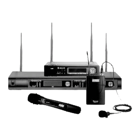
RELACART UR-222 Series Owner's manual

Installation and Operation
UR-222 Series
UR-222S SINGLE CHANNEL WIRELESS MICROPHONE SYSTEM
UR-222D DUAL CHANNEL WIRELESS MICROPHONE SYSTEM

P1 P2
Contents
01 Safety Operation and Notice .....................................................................................................
02 System Performance Feature ...................................................................................................
03 Receiver Installation Method ....................................................................................................
04 Packing List ............................................................................................................................
05 Receiver Front Panel Function Introduction ...............................................................................
06 Receiver Rear Panel Function Introduction ................................................................................
07 Transmitter Function Introduction .............................................................................................
Handheld microphone (UH-222) ...........................................................................................
Bodypack transmitter (UT-222) .............................................................................................
Boundary microphone (UB-222) ...........................................................................................
Desktop gooseneck microphone (UD-222) ............................................................................
08 Transmitter Battery Installation ................................................................................................
09 System Setup .........................................................................................................................
Receiver Setup ...................................................................................................................
Operating menu of the Receiver ...........................................................................................
10 User-friendly steps ....................................................................................................................
11 Technical Specification ............................................................................................................
P3
P4
P5
P6
P7
P9
P11
P11
P13
P14
P15
P17
P19
P19
P21
P22
P25
Thank you for choosing a RELACART professional wireless microphone system. You have
joined thousands of other satisfied customers. Our years of professional experience of
design and manufacturing to ensure our products’ quality, performance and reliability.

P3 P4
System Performance Feature
Safety Operation and Notice 0201
Key Features:
· International EIA STANDARD 1/2U, 1U metal chassis, combined with new-style compact and elegance LCD
display.
· Bright and easy-to-read LCD display shows working frequency or channel, RF/AF, diversity strengths;
transmitter battery level, mute and built-in electronic volume.
· Super wide frequency range UHF 521.25MHz~936.85MHz, automatic frequency selection, CPU intelligent
antenna diversity receiving.
· “AFS” Automatic frequency selection function, Press the “AFS” (Auto Frequency Selection) button 3S and
the receiver will auto-scan and lock on to an open, interference-free frequency.
· Press [IR] button to upload automatically the receiver frequency to the transmitter.
· Stable PLL (Phase Lock Loop frequency control) circuit, combining “IP address” and “NOISE DETECTION”
mute control function, can effectively separate the RF interference from computer equipment, song
machine and DVD in the working environment.
· Four frequency group in total, 40 channels, providing more than 400 adjustable frequency for the users.
· 134MHz wide bandwidth transmitter, four different frequency groups (400 mics) can be exchangeable,
greatly convenient for debugging and management.
· The handheld microphone: novel design, OLED display screen, showing battery level, working channel and
frequency. The tube is made by durable alloy, effectively protecting the circuit element and battery rack,
and with ergonomic grip.
· The new optimized circuit design, good sound quality, transmission distance is longer and more stable
· Precise low-power circuit design, use two AA alkaline battery, battery life is one time longer as common.
· Can match UH-222 handheld microphone, UT-222 bodypack transmitter, UD-222 desktop microphone or
UB-222 boundary microphone.
UR Series of condensed the technology essence that Relacart accumulated over a long period. With
advanced technology, sophisticated design, stable performance, with beautiful appearance, convenient
operation and attractive price, with superior professional quality to win the market competition. This
series is suitable for the nightclub of high requirements, multi-functional hall, hotel, conference room and
small to medium performance.
1. Please read instructions for safety operation carefully before installation and operation. Please save your safety
operation guide for future reference.
2. Do not scratch, bend, twist, stretch or heat the power cord as this may cause damage to the power cord, resulting
in a fire or electric shock.
3. Do not open the device shell, otherwise it may cause electric shock. If you need to repair, maintain or repair,
please contact your local agent.
4. Do not touch the power plug with wet hands as this may cause a fire or electric shock.
5. Do not attempt to modify this device. Failure to do so may result in personal injury or product malfunction.
6. Do not use this equipment near water.
7. If the power cord is damaged (such as a broken wire or bare core), obtain replacement parts from your dealer.
Continued use of the equipment with a damaged power cord may result in fire or electric shock.
8. To move the device he power, unplug the power cord, and unplug all connecting cables as this may damage the
cable, resulting in a fire or electric shock.
9. Before cleaning the device, unplug the power cord and unplug all connecting cables. Please clean it with a dry
soft cloth.
10. If the device is not in use for a long time, turn off the power, it is best to unplug the socket.
11. With the power plug and appliance coupler as the disconnecting device, it should be kept easy to operate.
12. For the safe use of the equipment and adequate ventilation, the minimum clearance around the equipment should
be maintained at a distance of 5 cm or more.
13. DO NOT cover the Ventilation holes, such as: newspaper / fabric / curtains and other items.
14. Equipment should not be placed on a bare flame source, such as: lit candles.
15. Battery should not be exposed to sunshine, roasted or other high temperature overheating environment.
16. Do not throw the waste battery, please put in the designated bins.
17. Water protection rating: IPX0
18. The device can be used normally in tropical / temperate climates.
19. This product is only suitable for safe use at the altitude of 2000m and below.
20. This symbol “ ” indicates that dangerous voltage constituting a risk of electric shock is present within this unit.
21. All Relacart products will be afforded one year free maintenance except for man-made damage, such as:
— the device is damaged by man-made factors.
— the device is damaged by improper operation.
— some components are damaged or loss after the self-disassembly.

P5 P6
Receiver Installation Method
03
Installation:
① For better operation the receiver should be at least 3ft (1m). above the ground and at least 3ft (1m).
away from a wall or metal surface to minimize reflections.
② Attached a pair of UHF antennas to the antenna input jacks, the antenna are normally positioned in the
shape of a “ V ” (both 45° from vertical) for best reception.
③ Keep antennas away from noise sources such as computer, digital equipment, motors, automobiles
and neon lights, as well as away from large metal objects
④ Keep open space between the receiver and transmitter for better reception.
⑤ The transmitter should be at least 6ft (2m). from the receiver
Packing List
04
(UR-222D)
(UR-222S)
Wireless microphone receiver *1
Wireless *2transmitter
BNC Antenna *2
External power adapter * 1
1 meter audio cable *2
1.5V AA battery *4
1 U rack mount kit (screw) * 1 set
Installation and operation * 1
UR-222D:
888.888MHz
CH00
888.888MHz
CH00
Wireless microphone receiver *1
Wireless *1transmitter
BNC Antenna *2
External power adapter * 1
1 meter audio cable *1
1.5V AA battery *2
1 U rack mount kit (screw) * 1 set
Installation and operation * 1
UR-222S:
888.888MHz
CH00
888.888MHz
CH00

P7 P8
Receiver Front Panel Function Introduction
05
(UR-222S)
(UR-222D)
1
7
234 5 6
1 253
7
24 4
656
Power switch: Turn on the receiver of power supply, long press to turn off the receiver.
“SYNC” button: When the infrared frequency window of the receiver and transmitter is aligned, press the
“SYNC” button, synchronization of transmitters via IR interface from receiver.
Infrared data transfer window (IR) : Transmit channel data from the receiver to the transmitter, so that they
are in the same frequency, in order to realize the synchronization.
LCD display: Display working channel or frequency, RF/AF, diversity strengths, transmitter battery level,
mute and operation menu.
“ / ” allow control button: Press the allow button to edit the menu parameter values; Long press “ ”
button to enter [AFS] auto- scan function and the receiver will auto- scan and lock on to an open,
interference-free frequency.
“SET” button: Press to step through menus, choose operating frequency and select receiver function
options.
1/2 wavelength BNC antenna: Used to receive radio transmitter for transmission.
1
3
4
5
2
6
7

P9 P10
Receiver r Panel Function IntroductionRea
06
1
(UR-222S)
1
(UR-222D)
123456
32 6 5 4 5 6
RF antenna diversity BNC input connector: suitable for connection of antenna A and antenna B, and
supports DC 8V/150mA power output.
Anti-pull device: used to fix the connecting cable of the external power adapter.
DC IN socket: connect to external power adapter.
LIFT/GND switch: control XLR pin 1 whether is contact GND.
Unbalanced audio output port (dual channel independent): The 6.3mm port can be connected to an
aux- level input of a mixer or power amplifier.
Balanced audio output port (dual channel independent): The XLR port can be used to connect a
standard 2 conductor shielded cable the receiver output to a balanced microphone level input on a
mixer.
4
1
3
2
5
6

P11 P12
Infrared data receiving window (IR): Synchronization of transmitters via IR interface from receiver.
Battery Cover: Unscrew it can reveal the battery compartment; When installing, replacing or setting the
infrared frequency, the battery cover must be opened.
RF power switch: HI is 50 mW, LO is 30 mW.
Battery Compartment: Insert 2 fresh 1.5V AA batteries. (Alkaline type is recommended. Please remember
to replace both batteries.)
Warn: Observe correct polarity as marked inside the battery compartment to avoid damage to the internal
electric parts.
The audio gain switch: 3 optional (0dB, -6dB, -12dB), the factory default setting is 0dB (no attenuation);
when the volume is too large, can according to the actual situation adjusted the gain (-6dB or -12dB ).
Transmitter Function Introduction
07
Microphone Head: It is the important part to transfer sound into audio signal. The microphone head is
separate to change other microphone head if needed.
OLED display: display the frequency, channel, lock and battery life. Battery indicator displays a
maximum of 4 bar segments. When it leaves 1 bar segment, the batteries should be replaced
immediately.
Power Button/Mute Button: Press the power button to turn on the transmitter, press the power button
1.5 second enter the mute status, press one more time to close the mute function. Long press 3
seconds to turn off the transmitter.
6
1 2 4 53
7
88
5
7
4
6
3
1
2
Handheld microphone (UH-222)
888.888MHz
CH00

P13 P14
3.5mm crimp type antenna: For transmitting a bodypack radio carrier.
Power Button/Mute Button: Press the power button to turn on the transmitter, press the power button 1.5
second enter the mute status, press one more time to close the mute function. Long press 3 seconds to
turn off the transmitter.
TA4M/LEMO input jack: Connect to a microphone or instrument cable.
OLED display: display the frequency, channel, lock and battery life. Battery indicator displays a maximum
of 4 bar segments. When it leaves 1 bar segment, the batteries should be replaced immediately.
Infrared data receiving window (IR): Synchronization of transmitters via IR interface from receiver.
“SET” button: Press to enter the selection or confirmation menu.
“ < / > ” allow control button: Press the allow button to edit the menu parameter values.
Battery Compartment: Pull to open the battery door and insert 2 fresh 1.5V AA batteries. (Alkaline type is
recommended. Please remember to replace both batteries.)
Warn: Observe correct polarity as marked inside the battery compartment to avoid damage to the internal
electric parts.
Power Button/Mute Button: Press the power button to turn on the transmitter, press the power button 1.5
second enter the mute status, press one more time to close the mute function. Long press 3 seconds to
turn off the transmitter.
OLED display: Display the frequency, channel, lock and battery life. Battery indicator displays a maximum
of 4 bar segments. When it leaves 1 bar segment, the batteries should be replaced immediately.
Infrared data receiving window (IR): Synchronization of transmitters via IR interface from receiver.
Battery Door Switch: Open the battery door by sliding the switch.
Battery Compartment: Insert 2 fresh 1.5V AA batteries. (Alkaline type is recommended. Please remember
to replace both batteries.)
Warn: Observe correct polarity as marked inside the battery compartment to avoid damage to the internal
electric parts.
1 2 3
888.888MHz
CH00
4
6 7 5 8
Bodypack transmitter (UT-222) Boundary microphone (UB-222)
6
2
3
1
8
7
5
4
888.888MHz
CH00
1 2 3 4 5
1
5
3
2
4

P15 P16
Power Button/Mute Button: Press the power button to turn on the transmitter, press the power button 1.5
second enter the mute status, press one more time to close the mute function. Long press 3 seconds to
turn off the transmitter.
OLED display: Display the frequency, channel, lock and battery life. Battery indicator displays a maximum
of 4 bar segments. When it leaves 1 bar segment, the batteries should be replaced immediately.
Infrared data receiving window (IR): Synchronization of transmitters via IR interface from receiver.
Desktop gooseneck microphone (UD-222)
6
1
3
2
Microphone rod: bending gooseneck design, can flexibly put the pickup head to any position.
Speaking Aperture: When you open the microphone to speak, this instruction light bright.
Gain knob: adjust the input signal size.
Low cut switch: cut off the low-frequency signal below 150Hz.
Battery Door Switch: Open the battery door by sliding the switch.
Battery Compartment: Insert 2 fresh 1.5V AA batteries. (Alkaline type is recommended. Please remember
to replace both batteries.)
Warn: Observe correct polarity as marked inside the battery compartment to avoid damage to the internal
electric parts.
4
9
7
888.888MHz
CH00
2 3 1
4
57
8
9
5
6
8

P17 P18
Transmitter Battery Installation
08
OPEN, Toggle Switch
1 12 23 3
11
22
33

P19 P20
System Setup
09
Receiver Setup
1. Make sure the transmitter is off before turning on the receiver.
2 Press the power switch on the receiver, LCD backlight will turn bright, and the normal display will be in 1-2
seconds. If the screen shows more than two signals, which means that there is a frequency interference
from outside, please change the other operating frequency.
3 Change the operating frequency by manual or by auto-scan mold:
a) Set the operating frequency by manual: press ◄/► to change the frequency, after the selected frequency
fleshes 4 times, the receiver will enter the selected frequency and show it on the LCD screen.
b) AFS Auto Frequency Scanning: long press ◄/► or 3 seconds, the receiver will auto scan about 30
seconds and lock on to an interference-free frequency.
4 Enter the main menu: long press SET button 3 seconds to enter the main menu. Press ◄/► button to select
the following menu: DISPLAY (frequency or channel display), GROUP (frequency group from 01-10),
LEVEL (electronic volume adjustment: -06 ~ +18dB), SQUELCH (squelch evel ontrol: 10 ~ 30dB), LOCK
(lock peration) and ILOT (pilot witch).
(1) DISPLY (frequency or channel display):
mode, touch ◄ arrow button, “FREQUENCY” flashes, if stopping on “FREQUENCY”, the LCD will
display the RF frequency; touch ► arrow button, “CHANNEL” flashes, if stopping on “CHANNEL”, the
LCD will display the operational channel. Press SET Button to confirm the desired choice, then LCD
return to its previously displayed contents. Finally press “SET” to confirm.
(2) GROUP (group display 01-10): select GROUP, then press SET to enter the edit mode, press◄/►
button to select any group of 01-10, Finally press SET to confirm.
(3) LEVEL (electrical level adjustment -06 ~ +18dB): select LEVEL, then press SET to enter the edit
mode, press ◄/► button, the adjustable electronic volume (-06 ~ +18dB). Finally press SET to confirm.
(4) SQELCH (squelch level control):
small data flashes to indicate edit, touch ◄/► button to scroll through the available choice for the
function. The squelch level is adjustable in ten 5dB steps, providing a 50dB range. Press SET Button to
confirm the desired choice, then LCD return to its previously displayed contents. Finally press “SET” to
confirm.
(Receiver squelch threshold is factory preset. When the transmitter too far away from the reception
range or receiver does not receive enough transmit power, you can adjust by yourself. Note that unless
absolutely necessary, please do not adjust the squelch threshold, if adjusted too low will produce
excessive noise, system operation will not stable.)
(5) :
button, it displays “ON”, if stopping on “ON”, the system enters lock mode, the user can not use any
button for any control; touch ► arrow button, it displays “OFF”, if stopping on “OFF”, the user can do any
control by any button. Press SET (LOCK ON)status, long press SET button 3 seconds, press ◄/►
button to select LOCK, then press ► , the screen freshes OFF, finally press SET to confirm, the lock
status is released.
(6) PILOT (pilot switch): select PILOT, then press SET to enter edit mode, press ◄/► button, can select
ON or OFF (on or off pilot). Finally press SET to confirm.

P21 P22
Operating menu of the Receiver:
CHANNEL
/ FREQUENCY,CHANNEL
CHANNEL: display the CHANNEL;
SET: store setting.
SET FREQUENCY
Current standard display;
FREQ: display the FREQUENCY
DISPLY
Switching between the standard
displays
SET
SET
SET
SET
SET
SET
SET
SET
SET
SET
SET
SET
/
/
/
/
/
/
/
/
/
/
/
/
10
/ :
01-10 group, group selection;
SET: store setting.
+18dB
/ : -06~+18dB; -06dB: Lowest output
level; 0dB: Default output level; +18dB:
Maximum output level; SET: store setting.
30dB
/ : 10dB~30dB; 30dB: Maximum
Squelch; 10dB: Minimum Squelch;
15dB: Default Squelch; SET: store setting.
ON
/ : ON, OFF
ON: Lock mode activated; OFF: Unlock
mode activated; SET: store setting.
ON
/ : ON, OFF;
ON: Switch off ; OFF: Switch on;
SET: store setting.
01
Group selection
-06dB
The lowest output level
10dB
Minimum Squelch
OFF
Unlock receivers
Lock mode activated or deactivated
OFF
Switch on
GROUP
Group display
LEVEL
Setting the audio output level
SQELCH
Adjusting the squelch threshold
LOCK
Activating the lock mode
PILOT
Pilot
STORED
STORED
STORED
STORED
STORED
EXIT
STOREDSTORED
User-friendly steps
10
1. After connecting the antenna and the power cable, press the power button to turn on the
receiver. When the display is lit, the power is turned on successfully. (As shown below)
2. Long press “ ” button on the receiver to enter Automatic Frequency Search (AFS) function.
(As shown below)
(UR-222D) (UR-222S)
(UR-222D) (UR-222S)

P23 P24
The searched channel automatically calculates the interference-free frequency. The “RF” light on the
receiver display is 0 grid. If not, you can repeat this action until a clean channel is found. (As shown
below)
3. The transmitter’s infrared window facing to the receiver IR port. Press the “SYNC” button. (As
shown below)
(UR-222D) (UR-222S)
Frequency alignment<15cm(6 in)
(UR-222D) (UR-222S)
888.888MHz
CH00
888.888MHz
CH00
888.888MHz
CH00
888.888MHz
CH00
888.888MHz
CH00
888.888MHz
CH00
888.888MHz
CH00
888.888MHz
CH00
The frequency of the transmitter and the receiver are synchronized. When talking with the
microphone, the “AF” signal in the display jumps to indicate that there is an audio output. (As
shown below)
(UR-222S)
Channel display (receiver and transmitter display the same frequency)
572.000MHz
CH06
572.000MHz
CH06
572.000MHz
CH06
572.000MHz
CH06

P25 P26
Technical Specification
11
UR-222S Single Channel Receiver UR-222D Dual Channel Receiver
Main Frame Size :
Receiving Channel:
Frequency Stability :
Carrier Frequency Range :
Modulation Mode :
Oscillation :
Sensitivity:
Bandwidth :
Max Deviation Range :
S/N :
T.H.D :
Frequency Response :
Operating Range :
Power Supply :
Dimension (mm) :
Weight :
Main Frame Size :
Receiving Channel:
Frequency Stability :
Carrier Frequency Range :
Modulation Mode :
Oscillation :
Sensitivity:
Bandwidth :
Max Deviation Range :
S/N :
T.H.D :
Frequency Response :
Operating Range :
Power Supply :
Dimension (mm) :
Weight :
EIA standard 1/2 U
Single Channel
±0.005% (-10 ~ 50 C)
521.25MHz ~ 936.85MHz
FM
PLL synthesized
S/N >60dB at 25 deviation
32MHz
±45KHz
>105dB
<0.7 @1KHz%
80Hz — 18KHz ±3dB
80M typical (in open space)
DC 12V/12W
205 (W) x 206 (D) x 43 (H)
Approximately 1.0kg
EIA standard 1U
Dual Channel
±0.005% (-10 ~ 50
521.25MHz ~ 936.85MHz
FM
PLL synthesized
S/N >60dB at 25 deviation
32MHz
±45KHz
>105dB
<0.7%@1KHz
80Hz — 18KHz ±3dB
80M typical (in open space)
DC 12V/12W
410 (W) x 206 (D) x 43 (H)
Approximately 1.9Kg

P27 P28
UH-222 Handheld Microphone UT-222 Bodypack Transmitter
Carrier Frequency Range:
Oscillation:
Harmonic Radiation:
Bandwidth:
Max. Deviation Range:
Microphone Element :
RF Output Power:
Battery:
Current Consumption:
Battery Current/Life:
Microphone Lengths (mm):
Weight:
Carrier Frequency Range:
Oscillation:
Harmonic Radiation:
Bandwidth:
Max. Deviation Range:
Input Connector:
RF Output Power:
Battery:
Current Consumption:
Battery Current/Life:
Dimension (mm):
Weight:
521.25MHz ~ 936.85MHz
PLL Synthesized
<45dBm
134MHz (It depends on the region)
±45KHz
Dynamic/Condenser (removable)
10MW/40MW
AA x 2
110mA (Typical)
Approximately 11 hours
52 (Φ) x 255 (L)
Approximately 235g (w/o battery)
521.25MHz ~ 936.85MHz
PLL Synthesized
<45dBm
134MHz (It depends on the region)
±45KHz
4-pin mini-XLR connector
10MW/40MW
AA x 2
110mA (Typical)
Approximately 11 hours
84 (H) x 66 (W) x 23 (D)
Approximately 155g (w/o battery)

P29 P30
UB-222 Boundary Microphone UD-222 Desktop Gooseneck Microphone
Carrier Frequency Range:
Modulation:
Harmonic Radiation:
Bandwidth:
Max. Deviation Range:
Elements:
Polar Pattern:
RF Output Power:
Dynamic Range:
Audio Potentiometer:
Frequency Response:
Low-cut Switch:
Battery:
Current Consumption:
Battery Current/Life:
Dimension (mm):
Weight:
Carrier Frequency Range:
Oscillation:
Harmonic Radiation:
Bandwidth:
Max. Deviation Range:
RF Output Power:
Gain Adjustment Range:
Low cut switch:
Battery:
Current Consumption:
Battery Current/Life:
Microphone Lengths (mm):
Weight:
521.25MHz ~ 936.85MHz
FM
<45dBm
134MHz (It depends on the region)
±45KHz
Fixed-charge back plate,
Cardioid (120°sound-pickup angle)
10mW
>95dB, A Weighting
-10 ~ 10dB
50Hz — 17KHz
200Hz/-6dB
AA x 2
130mA(Typical)
Approximately 9 hours
110 (W) x 40 (H) x 110 (D)
Approximately 505g
521.25MHz ~ 936.85MHz
PLL Synthesized
<50dBm
134MHz (It depends on the region)
±45KHz
10MW
10dB ~ +10dB
>200Hz
AA x 2
130mA (Typical)
Approximately 9 hours
340, 420 (default), 480
Approximately 830g (w/o battery)
This manual suits for next models
2
Table of contents
Other RELACART Microphone System manuals

RELACART
RELACART UR-222S User manual

RELACART
RELACART PM-160 Owner's manual

RELACART
RELACART PN-160 User manual

RELACART
RELACART ER-5700 Programming manual

RELACART
RELACART MS1 User manual

RELACART
RELACART UR-222S User manual

RELACART
RELACART HR-31S User manual

RELACART
RELACART UR-220D SERIES Owner's manual

RELACART
RELACART PM-320 User manual

RELACART
RELACART UR-111 Series User manual