BEROTEC Mofessor User manual

Manual
BEROTEC GmbH
MOFESSOR
M O F E S S O R
Automatic Chain Lubrication System

BEROTEC GmbH P a g e | 1
MOFESSOR
Manual
revision date 04/2020
contact for support:
contact@BEROTEC.de

BEROTEC GmbH P a g e | 2
MOFESSOR
Manual
Content
1. Introduction 3
2. Safety Instructions 3
2.1 Basic Safety Instructions..........................................................................3
2.2 Intended Use............................................................................................3
3. Design and Function 4
3.1 Scope of Delivery.....................................................................................4
3.2 Design......................................................................................................5
3.3 Function ...................................................................................................5
3.4 Rain / Offroad...........................................................................................6
3.5 Flushing....................................................................................................6
3.6 Temperature Influence.............................................................................6
3.7 Oil.............................................................................................................6
4. Installation 7
4.1 Preparations.............................................................................................7
4.2 Place of Installation..................................................................................7
4.3 Application Nozzle....................................................................................7
4.4 Oil Tank and Dispensing Valve................................................................9
4.5 Electrics....................................................................................................9
4.6 Commissioning.......................................................................................10
5. Operation and Maintenance 11
5.1 Adjusting the Oil Flow ............................................................................11
5.2 Refill.......................................................................................................12
5.3 Check and Maintenance ........................................................................12
6. Troubleshooting 13
7. Disposal 13

BEROTEC GmbH P a g e | 3
MOFESSOR
Manual
1. Introduction
We congratulate you on the purchase of the automatic chain lubrication
system "MOFESSOR“.
For a start, the system will not only extend the lifespan of your chain, it
will also reduce the maintenance expense of your motorbike.
If you have any criticism, tips or improvements, do not hesitate to contact
us.
2. Safety Instructions
2.1 Basic Safety Instructions
This manual contains the safety requirements for a proper and safe use
of the device. This manual has to be respected by the user. Please pay
attention to possible restrictions by country-specific law.
The chain lubrication system MOFESSOR operates with oil. If the
installation is done improperly, an uncontrolled loss of oil can lead to
soiling the motorbike or even worse safety issues.
For that reason, the system has to be checked carefully before every
departure and also after having done the first miles.
2.2 Intended Use
The chain lubrication system is intended for the use on chain-driven
motorbikes. For all other possible types of use, correct function cannot
be guaranteed. Its use is at your own risk and without any warranty. This
in particular means the use of non-authorized fluids.
The installation and the use have to be done according to this manual. In
case of any improper use of the device or neglecting this manual the
manufacturer is not liable for possible damages.

BEROTEC GmbH P a g e | 4
MOFESSOR
Manual
3. Design and Function
3.1 Scope of Delivery
•oil tank
•dispensing valve
•control unit
•switch
•applicator incl. Hose
•self-adhesive nozzle mount
•t-connector incl. filler pipe and end cap
•filling syringe
•chain oil MOFESSOR (250ml)
•cable tie package
•dispensing valve bracket incl. screws
•screwdriver
•rain-switch bracket
•oil hose mounts
•nozzle mounting clamp
•self-adhesive foam

BEROTEC GmbH P a g e | 5
MOFESSOR
Manual
3.2 Design
3.3 Function
•Turn on ignition
oLED flashes (self-test)
oMOFESSOR activated
•Start of chain lubrication
ofirst oil is dispensed after time interval
olevel 1 = 8 min / level 9 = 1,5 min
•Continious and automatic chain lubrication
odosing valve opens/closes automatically
ooil dispensing is adjusted to the ambient temperature
oLED flashes with every lubrication pulse
•Turn off ignition
oMOFESSOR deactivated
ono dripping while standing
ono power consumption

BEROTEC GmbH P a g e | 6
MOFESSOR
Manual
3.4 Rain / Offroad
By using the integrated rain-mode of the system, the oil flow can be
increased. A quick push on the button of the switch increases the oil flow
by the factor ten of the normal amount (red LED is activated). The rain-
mode will be set back to normal by either pushing the button of the switch
again or by turning of the ignition.
3.5 Flushing
To flush the system, the button of the switch has to be pushed and held
for 4 seconds. If activated, the red LED will give feedback by flashing fast.
This mode opens the dispensing valve permanently. This can be helpful
in the following situations:
•Bleeding the system (see chapter 4.6)
•Re-oiling a dry chain fast
•Restoring lubricity after a long ride in heavy rain or dirt
Warning: This mode leads to a very high oil flow!
3.6 Temperature Influence
The common use of a motorbike lies in a temperature span between -
10°C and +50°C.
Within this temperature span, the viscosity of oil changes by the factor
60. To guarantee a steady oil application on the chain, the control unit is
measuring the outside temperature permanently and adjusts the oil flow
automatically.
3.7 Oil
We recommend the use of BEROTEC chain oil, tried and tested with the
MOFESSOR.
The use of other types of oil is possible. However, so-called “biological
oils“ as well as sunflower oil have to be avoided. These kinds of oil have
the tendency to gum and will block the system.
Solvent-based liquids or water are not allowed.

BEROTEC GmbH P a g e | 7
MOFESSOR
Manual
Viscosity recommendation:
Viscosity /40°C / ASTM D 7042: 100 mm²/s
Viscosity-index / ASTM D 2270: 135
4. Installation
4.1 Preparations
For some models special installation manuals exist. See our website for
more information:
https://berotec.de/produkt/chain-oiler/?lang=en
4.2 Place of Installation
The MOFESSOR works gravity based. No part of the system should be
mounted close to hot components such as exhaust or engine. Under the
passenger seat you may find enough space for the installation. The self-
adhesive foam can be used for the installation to protect the parts from
scrubbing.
4.3 Application Nozzle
The application nozzle is made of copper and can be easily bended to
optimal application position. It is not functional to bend a very tight radius,
to kink the hose or to shorten the nozzle (capillary tube).

BEROTEC GmbH P a g e | 8
MOFESSOR
Manual
Possible mounting positions:
•On the side of the sprocket
ovisible
ocan get damaged when changing tires
orotation of the sprockets transports the oil into the chain
•On the side of the pinion
ounvisible and protected
orotation transports the oil into the chain
ohigher oil spill through higher rotation speed possible
•direct application to the chain
ooil needs to be applicated on the inside of the chain
oeasy to mount
ooil spill through wind turbulences of oil drips possible
onozzle can get hit by the chain
The best place for the installation of the nozzle always depends on the
motorbike.
For the installation of the nozzle, a nozzle mounting clamp, a self-
adhesive nozzle mount with clamping screw and self-adhesive hose
holders are provided. The oil hose can be locked into the hose holders.
The clamping screw (torque: 0,4NM) of the nozzle mount locks the nozzle
position. The surface needs to be degreased properly. Bended surfaces
are not suitable for the use of the self-adhesive mounts. The processing
temperature is at least 20°C.

BEROTEC GmbH P a g e | 9
MOFESSOR
Manual
4.4 Oil Tank and Dispensing Valve
The oil tankmust be installed with the hose connection at the lowest point.
The golden ventilation of the tank must be at the highest point, so that no
oil can escape during driving.
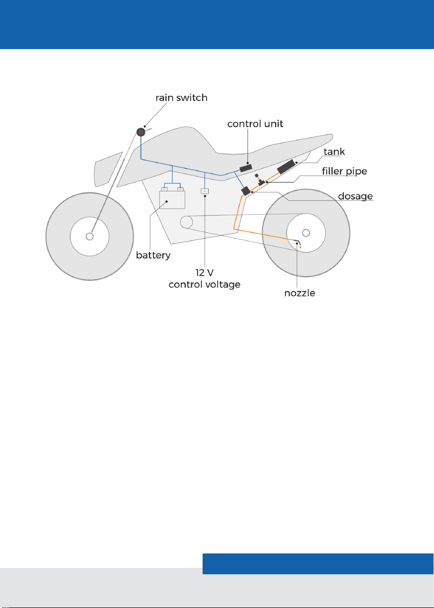
To refill the system, a t-connector is placed between oil tank and
dispensing valve (tube has to be cut). The end cap, located at the end of
the filler pipe, needs to be attached. The removable end cap should be
placed in an accessible area, so refilling can be done easily. The oil flow
direction is marked with an arrow on the dispensing valve. The tube
connectors can be removed by pushing the black locking edge.
4.5 Electrics
The MOFESSOR is delivered completely wired and tested. Don’t
connect/disconnect the plugs in energized condition.
Steps for the electrical installation:
1. Chose installation place for the control unit
2. Connect dispensing valve to the control unit
3. Place switch for rain-mode activation on the motorbike and
connect the switch to the control unit
→Avoid placing the cable of the switch close to the ignition
Warning: The wire connection at the backside of the switch is not made to
be bent forcibly. The switch will break and this is no issue of warranty. We
recommend laying the M8 connector side of the cable through the motorbike
and not the switch. Please mount washer and nut before. The cable on the
backside of the switch needs to be mounted completely traction-free,
especially with the handlebar at maximum steering angle.

BEROTEC GmbH P a g e | 10
MOFESSOR
Manual
4. Control voltage cable (black/white) connects to a 12V wire that is
switched by the ignition
Often this is already prepared by the manufacturer of the motorcycle,
often called “ACC2”. Otherwise The y-connector can be mounted to the
horn on most motorcycles (Except BMW) or the power supply of the
front- or taillight, the mark lighting can be used. The forked current is
very low (20mA), so there is no influence on the electrical system of your
bike.
5. Connect battery connection cable
Ring cable lugs need to be connected to the battery (positive pole = red;
negative pole = black).
Note: Battery connection cable and control voltage cable can also be
connected together to a switched current source (for example, on-board
socket), as long as an adequate power supply (520mA) is guaranteed.
The pluggable fuse holder is needed when connecting the red wire
directly to the battery. If you connect the red wire to a wire of your
electrical system that is already fused (max.10A) you don’t need the fuse
holder.
4.6 Commissioning
Before using the chain lubrication system, the chain should be cleansed.
Otherwise old dirt and grease will come lose due to the chain oil and get
centrifuged on the motorbike. We recommend our chain cleaning set.
The system can now be activated. If you turn on the ignition, the red LED
light inside the switch will flash once. This is a self-test of the system. The
system is now ready to go. You can also activate the rain mode with a
single push on the button of the switch.
The system needs to be bled after filling it for the first time or running it
completely empty (see chapter 5.2). Push the button of the switch for 4
seconds. The red LED will start flashing. The dispensing valve is now
open. Wait until oil starts dripping out of the nozzle. If the oil is very cold,

BEROTEC GmbH P a g e | 11
MOFESSOR
Manual
you can speed up this procedure by taking the oil-filled syringe and give
the system a light over-pressure. Keep in mind to close the golden
bleeding valve of the tank with your finger if you do this. When finished,
deactivate the flushing mode with a push on the button of the switch.
Warning: Before every departure have a close look at all parts of the system,
check if all hose connections are mounted properly and if there is no leaking
or malfunction.
5. Operation and Maintenance
5.1 Adjusting the Oil Flow
We recommend to initially set the rotary switch to level 1. This is the
setting for minimal oil flow. After 5 miles, check the amount of oil on the
chain and the whole system to ensure there is no malfunction. After
another 50 miles, start adjusting the rotary switch for a higher oil flow.
Find the optimal setting by turning the rotary switch step by step. Keep in
mind, changes in the oil flow need around 150 miles before a valid
evaluation is possible.
By following this procedure, soiling of the motorbike can be avoided.
Adjusting a high flowrate of chain oil can lead to the soiling of the rear
wheel. The oil flow has to be reduced immediately. A closed lubricity on
the chain rollers is sufficient and important.
The driver is responsible for a correct amount of oil. We are not liable for
damages caused by the oil flow being too low or too high.

BEROTEC GmbH P a g e | 12
MOFESSOR
Manual
1
0
2
3
4
5
6
7
8
9
1
0
2
3
4
5
6
7
8
9
1
0
2
3
4
5
6
7
8
9
Level 0: switched off
Level 1: low oil flow
Level 4: medium oil flow
1
0
2
3
4
5
6
7
8
9
Level 9: high oil flow
5.2 Refill
Refilling the chain oil is easy and fast. The syringe can be raised directly
on the cap of the oil bottle. The end cap of the filler pipe can be removed
by pushing the locking edge. With the syringe, oil can be filled into the
system. The oil tank is bleeding automatically. This has to be repeated
until the oil tank is full, but don’t overfill the tank, otherwise oil will leak out
of the ventilation of the tank.
5.3 Check and Maintenance
After the installation do some visual inspection to check the correct
setting of the oil flow.
The oil level of the oil tank should be checked and refilled every 1700
miles (long range tank every 3400 miles). Thus you can avoid the system
running dry.

BEROTEC GmbH P a g e | 13
MOFESSOR
Manual
6. Troubleshooting
problem
possible reason
action
no oil on the chain
- tank empty
- nozzle blocked
- kinked hose
- nozzle misadjusted
- electric connections not
properly connected
→refill oil
→clean nozzle
→check hose
→check nozzle position
→check connections
soiled rear wheel
- rain-mode not deactivated
after rain
- oil flow misadjusted
→put rain-mode switch in
field of view
→reduce oil flow
oil is leaking even
though ignition is turned
off
- control voltage cable is
connected to permanent
+12V
- hose damaged
→see chapter 4.5
→check hose
red LED isn’t working or
turning off by itself
- electric connections not
properly connected
- control voltage cable not
properly connected
→check connections
→see chapter 4.5
red LED is flickering
- rain-mode switch cable is
located too close to parts of
the ignition system
→re-lay cable
red LED is permanently
on
- control voltage too low
→check 12 V on control
voltage cable (black/white)
dosing valve doesn’t
work
- fuse broken
- connection failure
→check fuse / fuse holder
→check valve connection
7. Disposal
Nonfunctional systems shouldn’t be disposed as a whole but as individual parts
depending on the material. Non-recyclable parts have to be disposed according
to their type.

BEROTEC GmbH P a g e | 14
MOFESSOR
Manual

BEROTEC GmbH P a g e | 15
MOFESSOR
Manual
Other manuals for Mofessor
2
Table of contents
Other BEROTEC Lubrication System manuals