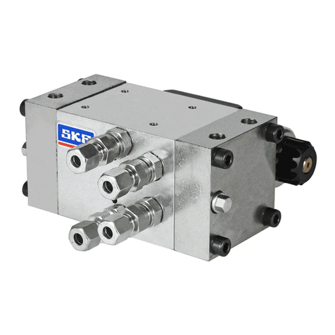
SKF HTL201 EEX User manual

EN
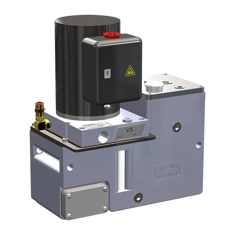
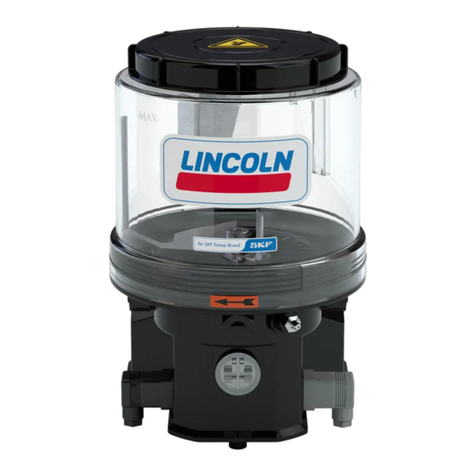
Hydraulically driven lubrication pump
HTL201EEX
Operating Instructions
following ATEX directive 2014/34/EU
951-181-016-EN
2022/11/24
Version 06

- 2 -
951-181-016
Version 06
EN
Jürgen Kreutzkämper
Manager R&D Germany
Stefan Schürmann
Manager PD Germany South
EU Declaration of conformity following ATEX directive 2014/34/EU, annex X
The manufacturer, SKF Lubrication Systems Germany GmbH, Walldorf Facilities, Heinrich-Hertz-Str. 2-8, DE - 69190 Walldorf hereby declares under
sole responsibility that the electrical equipment
Designation: Hydraulically driven pump to supply lubricants
Types: HTL201EEX
Part number: 642-41184-9
complies with all essential safety and health requirements of ATEX directive 2014/34/EU and the safety and health requirements of machinery directive
2006/42/EC at the time when first being launched in the market.
The technical documents according to:
ïATEX Directive 2014/34/EU Annex VIII No. 2 has been compiled and filed with the conformity assessment body (CE0123).
ïMachinery Directive 2006/42/EC Annex VII Part B has been compiled.
We undertake to transmit these in electronic form in response to a reasoned request by the national authorities. The manufacturer is authorized for the
technical documentation.
The following standards were applied in the applicable areas:
Standards
EN ISO 12100:2010 EN 1127-1:2019
EN 809:1998+A1:2009/AC2010 EN 1127-2:2014
EN ISO 80079-36:2016 EN ISO 80079-37:2016
The device must not be put into service until it has been established that the machinery into which it is to be incorporated is in compliance with the provi-
sions of ATEX Directive 2014/34/EU, Machinery Directive 2006/42/EC, and all other applicable Directives.
Walldorf, 2022/11/24
EU Declaration of conformity

- 3 - 951-181-016
Version 06
EN
Jürgen Kreutzkämper
Manager R&D Germany
UK Declaration of Conformity following to Regulation the Equipment and Protective Systems Intended for Use in Poten-
tially Explosive Atmospheres Regulations 2016 (2016 No. 1107)
The manufacturer, SKF Lubrication Systems Germany GmbH, Walldorf Plant, Heinrich-Hertz-Str. 2- 8, DE - 69190 Walldorf hereby declares, under its
sole responsibility, conformity of the device
Designation: Hydraulically driven pump to supply lubricants
Types: HTL201EEX
Part number: 642-41184-9
complies with all essential safety and health requirements of the regulation The Equipment and Protective Systems Intended for Use in Potentially Explo-
sive Atmospheres Regulations 2016 No. 1107, and the applicable health and safety requirements of the Supply of Machinery (Safety) Regulations 2008
No. 1597 at the time of placing on the market.
The technical documents according to:
ïThe Equipment and Protective Systems Intended for Use in Potentially Explosive Atmospheres Regulations 2016 No. 1107
ïSupply of Machinery (Safety) Regulations 2008 No. 1597 has been compiled
We undertake to transmit these in electronic form in response to a reasoned request by the national authorities. The authorized representative for the
compilation of the technical documentation is SKF (U.K.) Limited, 2 Canada Close, Banbury, Oxfordshire, OX16 2RT, GBR.
The following standards were applied in the applicable areas:
Standards
EN ISO 12100:2010 EN 1127-1:2019
EN 809:1998+A1:2009/AC2010 EN 1127-2:2014
EN ISO 80079-36:2016 EN ISO 80079-37:2016
The device must not be put into service until the machinery into which it is to be incorporated has been declared in conformity with the provisions of the
Equipment and Protective Systems Intended for Use in Potentially Explosive Atmospheres Regulations 2016 (2016 No. 1107), of the Supply of Machinery
(Safety) Regulations 2008 No. 1597 and all other applicable regulations
Walldorf, 2022/11/24
UK Declaration of Conformity
Stefan Schürmann
Manager PD Germany South

- 4 -
951-181-016
Version 06
EN
Description of the essential health and safety requirements according to 2006/42/EC, Annex I, which have been applied and fulfilled. Any essential health and
safety requirements not listed here are not relevant to this product.
No.: Essential health and safety requirement Applicable: Fulfilled:
1.1.1 Definitions YES YES
1.1.2 Principles of safety integration YES YES
1.1.3 Materials and products YES Partially
Regarding 1.1.3: Hazards due to the lubricant used must be assessed by the operator on the basis of the Safety Data Sheet (SDS) and, if necessary, protec-
tive measures must be taken.
1.1.5 Design of machinery to facilitate its handling YES YES
1.1.6 Ergonomics YES Partially
Regarding 1.1.6 Not completely fulfilled: The operator must ensure that the pump is integrated into the higher-level machine in such a way that the pump
can be operated and filled ergonomically.
1.2 Control systems YES YES
1.2.1 Safety and reliability of control systems YES YES
1.2.3 Starting YES YES
1.2.6 Failure of the power supply YES YES
1.3 Protection against mechanical hazards YES YES
1.3.1 Risk of loss of stability YES YES
1.3.2 Risk of break-up during operation YES YES
1.3.4 Risks due to surfaces, edges or angles YES YES
1.3.7 Risks related to moving parts YES YES
1.3.9 Risks of uncontrolled movements YES YES
1.5 Risks due to other hazards YES YES
1.5.6 Fire YES YES
Essential health and safety requirements according to 2006/42/EC, Annex II, No. 1 B

- 5 - 951-181-016
Version 06
EN
No.: Essential health and safety requirement Applicable: Fulfilled:
1.5.8 Noise YES YES
1.5.11 External radiation YES YES
1.5.13 Emissions of hazardous materials and substances YES YES
1.5.15 Risk of slipping, tripping, or falling YES YES
1.6 Servicing YES YES
1.6.1 Machinery maintenance YES YES
1.6.2 Access to operating positions and servicing points YES YES
Regarding 1.6.2 Not completely fulfilled: The operator must ensure that the pump is integrated into the higher-level machine in such a way that the pump
can be operated without danger.
1.6.4 Operator interventions YES YES
1.7 Information YES YES
1.7.1 Information and warnings on the machinery YES YES
1.7.1.1 Information and information devices YES YES
1.7.2 Warning of residual risks YES YES
1.7.3 Marking of machinery YES YES
1.7.4 Operating instructions/assembly instructions YES YES
1.7.4.1 General principles for the drafting of operating instructions/assembly instructions YES YES
1.7.4.2 Contents of the operating instructions/assembly instructions YES YES
1.7.4.3 Sales literature YES YES
Essential health and safety requirements according to 2006/42/EC, Annex II, No. 1 B

- 6 -
951-181-016
Version 06
EN Legal notice
Authorized local distributors
Great Britain
SKF (U.K.) Limited,
2 Canada Close, Banbury, Oxfordshire,
OX16 2RT, GBR.
North America
SKF Lubrication Business Unit
Lincoln Industrial
5148 North Hanley Road, St. Louis,
MO. 63134 USA
South America
SKF Argentina Pte. Roca 4145,
CP 2001 Rosario, Santa Fe
Copyright
© Copyright SKF
Alle Rechte vorbehalten.
Warranty
The instructions do not contain any informa-
tion on the warranty. This can be found in
our general terms and conditions.
Manufacturer
SKF Lubrication Systems Germany GmbH
Email: Lubrication-germany@skf.com
www.skf.com/lubrication
Berlin Plant
Motzener Strasse 35/37
12277 Berlin
Germany
Tel. +49 (0)30 72002-0
Fax +49 (0)30 72002-111
Walldorf Plant
Heinrich-Hertz-Strasse 2-8
69190 Walldorf, Germany
Germany
Tel.: +49 (0) 6227 33-0
Fax: +49 (0) 6227 33-259
Training courses
In order to provide a maximum of safety and
economic viability, SKF carries out detailed
training courses. It is recommended that the
training courses are attended. For more in-
formation please contact the respective SKF
Service address.
Warranty
The instructions do not contain any informa-
tion on the warranty. This can be found in
our general terms and conditions.
Disclaimer
The manufacturer shall not be held respon-
sible for damages caused by:
ïNon appropriate use
faulty assembly, operation, setting, main-
tenance, repair or accidents
ïUse of inappropriate lubricants
ïImproper or late response to malfunc-
tions
ïUnauthorized modifications of the prod-
uct
ïIntent or negligence
ïUse of non-original SKF spare parts
ïFaulty planning or layout of the central-
ized lubrication system
Liability for loss or damage resulting from
the use of our products is limited to the
maximum purchase price. Liability for con-
sequential damages of whatever kind is
excluded.

- 7 - 951-181-016
Version 06
EN
Table of contents
Table of contents
EU Declaration of conformity following ATEX directive 2014/34/EU,
annex X ..................................................................................................................2
UK Declaration of Conformity following to Regulation the Equipment and
Protective Systems Intended for Use in Potentially Explosive Atmospheres
Regulations 2016 (2016 No. 1107)....................................................................3
Explanation of symbols, signs and abbreviations...............................................9
1. Safety instructions...................................................................... 11
1.1 General safety instructions..................................................................11
1.2 General behaviour when handling the product.................................11
1.3 Intended use..........................................................................................12
1.4 Foreseeable misuse..............................................................................12
1.5 Modifications of the product................................................................12
1.6 Painting..................................................................................................13
1.6.1 Painting of plastic parts........................................................................13
1.7 Notes related to the CE marking.........................................................13
1.8 Prohibition of certain activities............................................................13
1.9 Inspections prior to delivery ................................................................13
1.10 Other applicable documents................................................................13
1.11 Markings on the product......................................................................14
1.12 Notes related to the UKCA marking ....................................................14
1.13 Notes related to the type identification plate.....................................14
1.14 Persons authorized to operate the pump ..........................................15
1.14.1 Operator.................................................................................................15
1.14.2 Specialist in mechanics ........................................................................15
1.14.3 Specialist in electrics ............................................................................15
1.14.4 Specialist for maintenance and repairs in potentially
explosive atmospheres.........................................................................15
1.15 Briefing of external technicians...........................................................15
1.16 Provision of personal protective equipment......................................15
1.17 Operation...............................................................................................16
1.18 Emergency stopping.............................................................................16
1.19 Transport, installation, maintenance, malfunctions, repair,
shutdown, disposal...............................................................................16
1.20 Initial commissioning / daily start-up.................................................18
1.21 Cleaning .................................................................................................18
1.22 Special safety instructions regarding explosion protection .............19
1.23 Expiry of the ATEX approval.................................................................20
1.24 Explosion protection marking..............................................................20
1.24.1 ATEX marking T6...T5...........................................................................20
1.25 General residual risks...........................................................................21
1.26 Residual risks ATEX...............................................................................22
2. Lubricants................................................................................... 24
2.1 General information .............................................................................24
2.2 Selection of lubricants..........................................................................24
2.3 Material compatibility...........................................................................24
2.4 Temperature characteristics................................................................24
2.5 Lubricants in explosive atmospheres .................................................25
2.6 Ageing of lubricants..............................................................................25
3. Overview, functional description ................................................ 26
4. Technical data ............................................................................. 29
4.1 Mechanics..............................................................................................29
4.2 Nominal output volumes .....................................................................30
4.2.1 Output diagram.....................................................................................30
4.3 Tightening torques ...............................................................................31
- 8 -
951-181-016
Version 06
EN Table of contents
5. Delivery, returns, and storage .................................................... 32
5.1 Delivery..................................................................................................32

5.2 Returns ..................................................................................................32
5.3 Storage...................................................................................................32
6. Installation.................................................................................. 33
6.1 General information .............................................................................33
6.2 Mechanical connection.........................................................................34
6.2.1 Minimum assembly dimensions .........................................................34
6.2.2 Installation bores ..................................................................................35
6.3 Hydraulic lines.......................................................................................36
6.4 Supply lines ...........................................................................................36
6.5 Equipotential bonding ..........................................................................36
6.6 Adjusting the output volume ...............................................................37
6.7 Filling with lubricant .............................................................................38
6.8 Venting of the pump .............................................................................39
6.9 Emergency lubrication .........................................................................40
6.10 Lubrication line connection .................................................................41
7. Initial start-up ............................................................................ 42
7.1 Inspections prior to initial start-up.....................................................42
7.2 Inspections during initial start-up ......................................................42
8. Operation.................................................................................... 43
9. Cleaning ...................................................................................... 44
9.1 Cleaning agents.....................................................................................44
9.2 Exterior cleaning ...................................................................................44
9.3 Interior cleaning....................................................................................44
10. Maintenance ............................................................................... 45
10.1 Clean or replace oil strainer.................................................................46
11. Troubleshooting.......................................................................... 47
12. Repairs........................................................................................ 48
12.1 Replacing the pressure control valve..................................................48
12.2 Replacing the reservoir ........................................................................49
13. Shutdown and disposal............................................................... 51
13.1 Temporary shutdown ...........................................................................51
13.2 Final shutdown and disassembly ........................................................51
13.3 Disposal..................................................................................................51
14. Spare parts................................................................................. 52
14.1 Pump HTL 201 EEX assy. ....................................................................52
14.2 Lubricant reservoir assy. ......................................................................52
14.3 Pressure control valve..........................................................................53
14.4 Oil strainer .............................................................................................53
14.5 Closure screw ........................................................................................53
14.6 Filler fitting.............................................................................................54
14.7 Emergency lubrication fitting..............................................................54
14.8 Flat packing............................................................................................54

- 9 - 951-181-016
Version 06
EN
Explanation of symbols, signs and abbreviations
General warning Dangerous electrical voltage Risk of falling Hot surfaces
Unintentional intake Crushing hazard Pressure injection Suspended load
Electrostatically sensitive
components Risk of explosion Explosion-protected
component
Wear personal protective
equipment (goggles)
Wear personal protective
equipment (face shield)
Wear personal protective
equipment (gloves)
Wear personal protective
equipment (protective clothes)
Wear personal protective
equipment (safety shoes)
Disconnect product from
mains General obligation
Keep unauthorized persons
away Protective earth Safety extra-low voltage
(SELV) Safe galvanic isolation (SELV)
CE marking Disposal, recycling Disposal of waste electrical
and electronic equipment
Warning level Consequence Probability Symbol Meaning
DANGER Death, serious
injury imminent üChronological guidelines
WARNING Death, serious
injury possible ñLists
CAUTION Minor
injury possible Refers to other facts, causes, or consequences
NOTICE Property damage possible
The following abbreviations may be used within these instructions. Symbols within safety notes mark the kind and source of the hazard.

- 10 -
951-181-016
Version 06
EN Explanation of symbols, signs and abbreviations
Abbreviations and conversion factors
re. regarding °C degrees Celsius °F degrees Fahrenheit
approx. approximately K Kelvin Oz. Ounce
i.e. that is N Newton fl. oz. fluid ounce
etc. et cetera h hour in. inch
poss. possibly s second psi pounds per square inch
if appl. if applicable d day sq.in. square inch
a.a.r. as a rule Nm Newtonmeter cu. in. cubic inch
incl. including ml millilitre mph miles per hour
min. minimum ml/d millilitre per day rpm revolutions per minute
max. maximum cc cubic centimetre gal. gallon
min. minute mm millimetre lb. pound
etc. et cetera l litre hp horse power
e.g. for example dB (A) Sound pressure level kp kilopound
kW kilowatt > greater than fpsec feet per second
U Voltage < less than conversion factors
R resistance ± plus/minus Length 1 mm = 0.03937 in.
I current Ø diametre Area 1 cm² = 0.155 sq.in
V volt kg kilogram Volume 1 ml = 0.0352 fl.oz.
W watt rh relative humidity 1 l = 2.11416 pints (US)
AC alternating current jabout Mass 1 kg = 2.205 lbs
DC direct current = equal to 1 g = 0.03527 oz.
A ampere % per cent Density 1 kg/cc = 8.3454 lb./gal(US)
Ah ampere hour ‰ per mille 1 kg/cc = 0.03613 lb./cu.in.
Hz frequency [Hertz] ggreater than Force 1 N = 0.10197 kp
nc normally closed fless than Pressure 1 bar = 14.5 psi
no normally open contact mm2square millimetre Temperature °C = (°F-32) x 5/9
OR logical OR rpm-1 revolutions per minute Output 1 kW = 1.34109 hp
&logical AND Acceleration 1 m/s² = 3.28084 ft./s²
Speed 1 m/s = 3.28084 fpsec.
1 m/s = 2.23694 mph

1
- 11 - 951-181-016
Version 06
EN
1. Safety instructions
1.1 General safety instructions
ïThe owner must ensure that safety infor-
mation has been read by any persons en-
trusted with works on the product or by
those persons who supervise or instruct
the before-mentioned group of persons.
In addition, the owner must also ensure
that the relevant personnel are fully fa-
miliar with and have understood the con-
tents of the Instructions. It is prohibited to
commission or operate the product prior
to reading the Instructions.
ïThese Instructions must be kept for fur-
ther use.
ïThe described products were manufac-
tured according to the state of the art.
Risks may, however, arise from a usage
not according to the intended purpose
and may result in harm to persons or
damage to material assets.
ïAny malfunctions which may affect safety
must be remedied immediately. In addi-
tion to these Instructions, general statu-
tory regulations for accident prevention
and environmental protection must be
observed.
1.2 General behaviour when handling the
product
ïThe product may be used only in aware-
ness of the potential dangers, in proper
technical condition, and according to the
information in these instructions.
ïFamiliarize yourself with the functions
and operation of the product.The speci-
fied assembly and operating steps and
their sequences must be observed.
ïAny unclear points regarding proper
condition or correct assembly/ operation
must be clarified. Operation is prohibited
until issues have been clarified.
ïUnauthorized persons must be kept
away.
ïPrecautionary operational measures and
instructions for the respective work must
be observed.
ïResponsibilities for different activities
must be clearly defined and observed.
Uncertainty seriously endangers safety.
ïSafety-related protective and emergency
devices must not be removed, modified
or affected otherwise in their function
and are to be checked at regular intervals
for completeness and function.
ïIf protective and safety equipment has to
be dismantled, it must be reassembled
immediately after finishing the work, and
then checked for correct function.
ïRemedy occurring faults in the frame of
responsibilities. Immediately inform your
superior in the case of faults beyond your
competence.
ïWear personal protective equipment.
ïNever use parts of the centralized lu-
brication system or of the machine as
standing or climbing aids.

- 12 -
951-181-016
Version 06
EN 1. Safety instructions
1.3 Intended use
Supply of lubricants within a centralized lu-
brication system following the specifications,
technical data and limits stated in these
Instructions:
Usage is allowed exclusively for professional
users in the frame of commercial and eco-
nomic activities.
1.4 Foreseeable misuse
Any usage differing from the one stated in
these Instructions is strictly prohibited, par-
ticularly a usage:
ïoutside the indicated temperature range
ïwith non-specified means of operation
ïwithout adequate pressure control valve
ïin areas with aggressive or corrosive ma-
terials (e.g. high ozone pollution). These
may affect seals and painting.
ïin areas with harmful radiation (e. g. ion-
ising radiation)
ïwithout an adequate and tested switch-
off device for operation of explosion-
protected devices in ATEX category I M2
ïto supply, transport, or store hazardous
substances and mixtures in accordance
with annex I part 2-5 of the CLP regula-
tion (EC 1272/2008) and marked with
GHS01 - GHS06 and GHS08 hazard
pictograms.
ïto feed, forward, or store gases, liquefied
gases, dissolved gases, vapours, or fluids
whose vapour pressure exceeds normal
atmospheric pressure (1013 mbar) by
more than 0.5 bar at the maximum per-
missible operating temperature.
ïto feed, forward, or store lubricants con-
taining volatile solvents
ïin explosive gas and vapour atmos-
pheres, the ignition temperature of which
is smaller than 125 % of the maximum
surface temperature
ïin explosive dust atmospheres, the mini-
mum ignition and glow temperature of
which is smaller than 150 % of the maxi-
mum surface temperature
ïIn a different, more critical potentially
explosive atmosphere than stated on
the type identification plate of the pump
used.
ïwith damaged or lacking ATEX painting or
ATEX painting done wrongly later on. The
painting must comply with the standards
valid for ATEX.
ïto operate the pump without lubricant
This results in a heating up of bearing
points up to the ignition temperature
range). Fill the pump reservoir at regular
and adequate intervals with suitable
lubricant.
1.5
Unauthorized conversions or modifica-
tions may result in unforeseeable impacts
on safety. Therefore, any unauthorized
conversions or modifications are expressly
prohibited.

1
- 13 - 951-181-016
Version 06
EN
1. Safety instructions
1.6 Painting
The pump is delivered in unpainted condi-
tion and can be operated without painting. If
the pump shall be painted, the painting must
comply with the requirements of the stand-
ards valid for ATEX. Should a new painting
be required, for example, after repair or cor-
rosion, etc., make sure to also comply with
the requirements of the standards valid for
ATEX. Carefully mask all seals before paint-
ing. Ensure that the painting is compatible
with the sealing materials employed.
1.6.1 Painting of plastic parts
Painting of plastic parts and seals, if any,
is prohibited. Remove or completely tape
parts concerned before painting the superior
machine.
1.9 Inspections prior to delivery
The following inspections were carried out
prior to delivery:
ïSafety and functional tests
ïTests in accordance with ATEX directive
2014/34/EU
1.10 Other applicable documents
In addition to these instructions, the fol-
lowing documents must be observed by the
respective target group:
ïOperational instructions and approval
rules
ïSafety data sheet (MSDS) of the lubricant
and the hydraulic oil used.
ïOperator's explosion protection docu-
ment.
Where appropriate:
ïProject planning documents
ïAny documents of other components
required to set up the centralized lubrica-
tion system
1.7 Notes related to the CE marking
CE marking is effected following the require-
ments of the applied directives:
ï2014/34/EU
Directive relating to equipment and
protective systems for use in explosive
atmospheres (ATEX)
Reference on Pressure Equipment Directive
2014/68/EU
Because of its performance data the product
does not achieve the limit values defined in
Article 4 (1) (a) (ii) and is therefore excluded
from the scope of application of Pressure
Equipment Directive 2014/68/EU following
Article 1 (2) (f).
1.8 Prohibition of certain activities
Due to potential sources of faults that may
not be visible or due to legal regulations
the following activities may be carried out
by manufacturer specialists or authorized
persons only:
ïRepairs or changes to the pump hous-
ing, the pump element or to the reservoir
vent

- 14 -
951-181-016
Version 06
EN 1. Safety instructions
1.11 Markings on the product
Marks the equipotential bonding
connection on the bottom of the
product
Marks the bore from which a
small amount of grease leaks in
case of maximum filling of the
reservoir
Warning of hot surfaces.
Wear suitable eye protection
1.12 Notes related to the UKCA marking
The UKCA conformity marking con-
firms the product’s conformity with
the applicable legal provisions of
Great Britain.
1.13 -
tion plate
The type identification plate states important
characteristics such as type designation, or-
der number, and regulatory characteristics.
To ensure that the loss of data due to an il-
legible type identification plate is avoided,
the characteristics should be entered in the
Instructions.
Model: ________________________________
P. No. ________________________________
Series ________________________________
SKF Lubrication Systems Germany GmbH
Made in Germany D-69190 Walldorf
09/16
Model:
P.No.:
Series:
pmax = 270 bar / 3916 psi
Hydr.pmax = 210 bar / 3045 psi
Hydr.pmin = 80 bar / 1160 psi
HTL-K7-1,5XF EEX
642-41184-9
2010113679
≤Ta≤-25 °C +65 °C
II 2G Ex h IIC T6...T5 Gb
II 2D Ex h IIIC T80 °C...T100 °C Db
I M2 Ex h I Mb

1
- 15 - 951-181-016
Version 06
EN
1. Safety instructions
1.14 Persons authorized to operate the
pump
1.14.1 Operator
A person who is qualified by training, know-
ledge and experience to carry out the func-
tions and activities related to normal opera-
tion. This includes avoiding possible hazards
that may arise during operation.
1.14.2 Specialist in mechanics
Person with appropriate professional educa-
tion, knowledge and experience to detect
and avoid the hazards that may arise during
transport, installation, start-up, operation,
maintenance, repair and disassembly.
1.14.3 Specialist in electrics
Person with appropriate professional educa-
tion, knowledge and experience to detect
and avoid the hazards that may arise from
electricity.
1.14.4 Specialist for maintenance and
repairs in potentially explosive
atmospheres
A person who is qualified by training, know-
ledge and experience to identify and assess
possible risks and hazards during work on
the machine or partial components in po-
tentially explosive areas and to initiate suita-
ble measures to prevent such risks. The spe-
cialist has knowledge of the different ignition
protection types, installation procedures and
zone divisions. He is familiar with the rules
and regulations relevant for his activities and
explosion protection, in particular with ATEX
directives 2014/34/EU and 1999/92/EC.
1.15
Prior to commencing the activities, external
technicians must be informed by the opera-
tor of the company safety provisions, the
applicable accident prevention regulations
to be maintained, and the functions of the
superordinate machine and its protective
devices.
1.16 Provision of personal protective
equipment
The operator must provide suitable personal
protective equipment for the respective
location of operation and the purpose of
operation. For work in potentially explosive
atmospheres this also includes ESD clothing
and ESD tools.

- 16 -
951-181-016
Version 06
EN 1. Safety instructions
1.17 Operation
The following must be observed during
commissioning and operation.
ïAny information within this manual and
the information within the referenced
documents
ïAll laws and regulations to be complied
with by the user
1.18 Emergency stopping
In case of an emergency stop the pump sta-
tion by:
ïSwitching off the superior machine or
system in which the pump station has
been integrated.
ïActuating the emergency stop switch of
the superior machine.
ïEnsure through suitable measures that
movable or detached parts are immobi-
lized during the work and that no limbs
can be caught in between by inadvertent
movements.
ïAssemble the product only outside of the
operating range of moving parts, at an
adequate distance from sources of heat
or cold. Other units of the machine or ve-
hicle must not be damaged or impaired in
their function by the installation.
ïDry or cover wet, slippery surfaces ac-
cordingly.
ïCover hot or cold surfaces accordingly.
ïWork on possible supplementary elec-
trical components must be carried out
by electrical specialists only. Observe
any waiting periods for discharging, if
necessary. Carry out works on electrical
components using voltage insulated tools
only.
1.19 Transport, installation, maintenance,
malfunctions, repair, shutdown,
disposal
ïAll relevant persons must be informed
of the activity prior to starting any work.
Observe the precautionary operational
measures and work instructions.
ïCarry out transport using suitable trans-
port and hoisting equipment on suitable
ways only.
ïMaintenance and repair work can be
subject to restrictions at low or high tem-
peratures (e.g. changed flow properties of
the lubricant).Therefore, where possible,
try to carry out maintenance and repair
work at room temperature.
ïPrior to performing work, the product
and the machine, into which the product
will be integrated, must be depressur-
ized and secured against unauthorized
activation.

1
- 17 - 951-181-016
Version 06
EN
1. Safety instructions
ïEnsure proper connection of the equipo-
tential bonding connection.
ïUndertake drilling at non-critical, non-
load bearing parts only. Use any available
boreholes. Do not damage lines and ca-
bles when drilling.
ïObserve possible abrasion points. Protect
the parts accordingly.
ïAll components used must be designed
for:
- maximum operating pressure
- maximum / minimum ambient tem-
perature
- the lubricant to be supplied
- the ATEX zone required
- the operating / ambient conditions at
the place of usage.
ïNo parts of the centralized lubrication
system may be subjected to torsion,
shear, or bending.
ïCheck all parts prior to their usage for
contamination and clean, if necessary.
ïLubricant lines should be primed with
lubricant prior to installation. This makes
the subsequent ventilation of the system
easier.
ïObserve the specified tightening torques.
When tightening, use a calibrated torque
wrench.
ïWhen working with heavy parts use suit-
able lifting tools.
ïAvoid mixing up or wrong assembly of
dismantled parts. Mark these parts ac-
cordingly.

- 18 -
951-181-016
Version 06
EN 1. Safety instructions
1.20 Initial commissioning / daily start-up
Ensure that:
ïAll safety devices are completely available
and functional
ïAll connections are correctly connected
ïAll parts are correctly installed
ïAll warning labels on the product are
present completely, highly visible and
undamaged
ïIllegible or missing warning labels are to
be replaced without delay
ïThe machine is correctly earthed
ïThe equipotential bonding connection is
properly connected
1.21 Cleaning
ïRisk of fire and explosion when using
inflammable cleaning agents Only use
non-flammable cleaning agents suitable
for the purpose.
ïDo not use aggressive cleaning agents.
ïThoroughly remove residues of cleaning
agents from the product.
ïWork on possible supplementary electri-
cal components must be carried out by
electrical specialists only.
ïMark damp areas accordingly.
ïDo not use sharp-edged or spark-gen-
erating tools for cleaning.

1
- 19 - 951-181-016
Version 06
EN
1. Safety instructions
1.22 Special safety instructions
regarding explosion protection
ïAlways behave so that explosion hazards
are avoided.
ïA written work approval from the opera-
tor is required prior to working in poten-
tially explosive areas. Keep unauthorized
persons away.
ïThere must be no indications that parts
of the explosion protection are missing or
are not working. Should such indications
become apparent, switch off the machine
and inform a superior without delay.
ïMeasures for explosion protection must
never be deactivated, modified or by-
passed.
ïIt is forbidden to bring in ignition sources
such as sparks, open flames and hot sur-
faces in potentially explosive areas.
ïCheck the machine at regular intervals for
damage which may represent an ignition
risk.
ïThe ignition temperature of the hydraulic
oil must lie at least 50 K over the maxi-
mum admissible surface temperature of
the components.
ïThe ignition temperature of the ambient
explosive gas and vapour atmospheres
must be greater than 125 % of the maxi-
mum surface temperature.
ïThe minimum ignition and glow tem-
perature of the ambient explosive dust
atmospheres must be greater than 150 %
of the maximum surface temperature
ïThe limits of use related to explosion pro-
tection are clearly defined by the device
categories, gas and dust groups as well
as temperature classes stated in the ex-
plosion protection marking. In any case,
also if dust group IIIC is specified, light-
metal dusts as explosive ambient media
are prohibited
ïOnly use tools and clothing which are
permitted for use in potentially explosive
areas (ESD).
ïTransport, installation, repairs and work
on electrical components may only be
carried out, if it has been ensured that the
atmosphere is not potentially explosive.
ïRepairs or modifications to machines
which are protected against explosions
may be carried out only by the manufac-
turer or by a workshop recognized by a
named institution and confirmed in writ-
ing. If the work is not carried out by the
manufacturer, the repairs must be ap-
proved by a named expert and confirmed
in writing.
Repairs are to be marked by a repair sign
on the machine, stating the following:
- Date
- Executing company
- Type of repair
- If applicable, expert's code
ïTransport damages can result in the loss
of the explosion protection. If transport
damages can be seen, do not assemble
the product nor put it into operation.
ïAll parts of the grounding concept must
be correctly available and connected with
the superordinate machine.
ïIf transport lugs are dismantled after
set-up, the threaded bores must be per-
manently sealed in accordance with the
protection class.
ïAll parts are to be checked regularly for
corrosion. Replace the affected parts.

- 20 -
951-181-016
Version 06
EN 1. Safety instructions
ïHandle the materials so that no sparks
generated by tilting, falling, sliding, rub-
bing, impacting, etc. If needed, cover
materials with suitable means.
ïThe operator must check critically
whether operation without a low-level
signal might lead to a new risk potential.
If this cannot be ascertained, provide a
low-level signal or suitable organisational
measures for monitoring of the bearing
point temperature.
ïAvoid dust accumulation and remove
dust immediately. Dust accumulations
have a thermally insulating effect and, if
whirled up, generate the formation of a
potentially explosive atmosphere.
ïThe product must be integrated in the
operator's lightning protection concept.
ïThe product must be integrated in the
operator's switch-off concept for explo-
sion protected equipment in ATEX cat-
egory I M2.
ïTerminal boxes must be firmly closed and
the cable breakthroughs correctly sealed.
ïAdditional electrical monitoring devices
must be firmly connected and correctly
adjusted.
1.23 Expiry of the ATEX approval
The ATEX certificate for this product expires
through:
ïUse not in accordance with the intended
purpose
ïunauthorized modifications.
ïUse of non-original
SKF spare parts
ïnon-observance of these instructions
and other applicable documents.
ïUse of non-specified lubricants
ïNon-observance of the specified mainte-
nance and repair intervals
ïOperation with damaged or lacking ATEX
painting or ATEX painting done wrongly
later on and not complying with the
standards applicable for ATEX
Operation is permitted only, if in compliance
with:
ïAll information given in these instructions
or stated in the referenced documents.
ïAll laws and regulations to be complied
with by the user.
ïInformation on explosion protection
according to directive 1999/92/EC
(ATEX 137).
ïATEX approval.
1.24 Explosion protection marking
Gas: II 2G Ex h IIC T6...T5 Gb
Dust: II 2D Ex h IIICT80 °C...T 100 °C Db
Mining: I M2 Ex h I Mb
The explosion protection marking is addi-
tionally found on the type identification plate.
1.24.1 ATEX marking T6...T5
The surface temperature of the pump basi-
cally depends on the temperature of the hy-
draulic oil used. To determine the maximum
temperature occurring on the product, for
safety reasons, there should be considered
a temperature increase of 10 K compared to
the temperature of the hydraulic oil used.
Other manuals for HTL201 EEX
1
Table of contents
Other SKF Lubrication System manuals

SKF
SKF 729101/300MP User manual

SKF
SKF Lubrigun 85100 Series Instruction Manual

SKF
SKF VectoLub VE1B Guide

SKF
SKF GVP-S-034-3D+924 User manual

SKF
SKF LAGD 400 User manual

SKF
SKF CLU4eco PDYE Series Quick start guide

SKF
SKF GVP-S-049-1 User manual

SKF
SKF KGF Series Configuration guide

SKF
SKF HS04 User manual

SKF
SKF 501-301-310-S1 User manual
Popular Lubrication System manuals by other brands

Atlanta
Atlanta BKI 109 e operating instructions

BEROTEC
BEROTEC Mofessor manual

IMI
IMI norgren Micro-Fog L68C Installation & maintenance instructions

SMC Networks
SMC Networks AL430-1 Series Operation manual

DROPSA
DROPSA MiQueL EXT User Operating and Maintenance Manual

Simatec
Simatec simalube 60 User manual & technical information