Relcross Door Controls 4040XP.TANDEM.61.US28 User manual

1
4040XP.TANDEM.61.US28

2
–4040XP.TANDEM.61.US28
You have been provided with the following:
4040XP.TANDEM.61. RH Extra Heavy Duty Closer - Silver, Top Jamb . Regular
Duty Arm (Right Hand)
-clockwise closing doors (viewed in plan)
and/or
4040XP.TANDEM.61. LH Extra Heavy Duty Closer - Silver, Top Jamb . Regular
Duty Arm
) models suit clockwise closing doors (viewed in plan)
Part #1 4040XP-3071.US28 Closer Mechanism – Non-Handed
(Prepared for Top Jamb (Push Side)
Part #3 4040XP-72MC.US28 Metal Closer Cover – Handed
Lower – arm & bush connector
Upper – Cut only to accommodate bush connector

3
Part #4 4040XP-159 Arm Screw – (- see page 2)
Secures the closer arm to the lower mechanism. Note the mark on the arm and the
lower closer mechanism pinion -load.
See below (page 7)
Part #5 4040XP-31 Cover Screw – (- see page 2)
Secures the metal covers 3/32
Allen key provided). The sequence of assembly is important. The upper cover must
(page 9)
Part #6 4040XP-3077.US28 Regular Duty Door Closer Arm – Non-Handed ()
via the hex hole on the main arm (see also Part #4). The arm
shoe (bull nose trim) door. See below (page 7)
Part # 7 4040XP-TANDEM.PLATE.US28 – Non-
Fixed to the top jamb (push side) of the door/frame assembly. Accommodates the
closer mechanisms (see Part #1). *Drilled and tapped for closer
and prepared with 11 for M6 x
16mm machine screws.
–
from the drawing (dictated by frame detail)

4
Part #8 4040XP-TANDEM.BUSH Connector –
We have supplied one complete closer fully assembled (but LESS the closer arm) to show you how
the partr guide for assembly.
NB – there is no part #2
The 4040XP.TANDEM.61Extra Heavy Duty Closer is designed to suit doors <272 kilos.
Internal doors widths <1524mm and perimeter door widths <1220mm. F
Maximum hinge open width 127mm. For doors hung on
NB - When using pivots or swing clear hinges, always locate the closer and shoe from the
centre line – i.e., the pivot point.
–
Establish the hand of the door:
Plan View
Select the correct handing – clearly marked on each complete box.

5
–
(Maximum Opening Angle 120°)
-TANDEM.PLATE.US28 – Part #7 to the top jamb (push side):
For (Right Hand Opposite)
– . The lower most row of drilled and tapped holes -
i.e., those closest to the edge of the plate - must be within 17mm of the underside of the reveal or
stop face, as indicated (see below). This will ensure the closer arm passes beneath the underside of
the reveal as the door opens.
lower if necessary
movement through the door without the closer or
– B
tapped holes, asindicated (see above). This dimension istaken from the centre line of the pivot point
of the door.
Lateral Arm Shoe Alignment -. This dimension istaken from the centre line ofthe pivot
point of the door.
(Dcloser mechanisms inplace yet).
11 (assumes steel doors
).

6
–
the lower* 4040XP-3071.US28 Closer Mechanism – Part #1 to the 4040XP-
TANDEM.PLATE.US28
front of the
spring power dial at this point.
bolts provided.
*Labelled accordingly
–
the upper* 4040XP-3071.US28 Closer Mechanism – Part #1 to the 4040XP-
TANDEM.PLATE.US28 via the 4040XP-TANDEM.BUSH connector – Part #8
Place the 4040XP-
closer mechanism’s lower
tap the bush connector the
front of . Do not adjust the hydraulic valves or the spring power dial at this point.
Fix to the plate using the remaining
*Labelled accordingly
in place since you will need access to the hydraulic valves
and the spring power dials
power dials at this point.

7
(see page 8) –
the lower mechanism has a black mark at the
-load purposes (see below).
–
4040XP-3077.US28 Regular Duty Door Closer Arm – Non-Handed – Part #6
Place the closer arm hex hole onto the of
the lower
hole) align correctly. Once the closer arm is in
gently tap the
arm in place fully. Use the 4040XP-159 Arm
Screw – .
The hex hole at the end of the closer arm engages with the lower
100° angle to the closer
view from the underside of the instal.
-
Pre-load the arm to 90° as shown - Rotate the
main arm such that the fore arm meets the door
at a 90° angle. This will ensure the closer pulls
is complete
the closing arc.

8
–
hydraulic control.
–
right hand doors will be a mirror image).
In detail – per mechanism:
r speed open the door back to the maximum angle
manner, you do not need
to make any adjustment.
–
s 10 & 11.
NB - Once correctly adjusted you should never need to return to the closer mechanism unless
external circumstances change.

9
–
Fixing the 4040XP-72MC.US28 Metal Closer Covers – Part #3 and Part #5
Upper Cover –
upper 4040XP-3071.US28 Closer Mechanism has the 4040XP-31 Cover Screws in
place already. Select the Upper Cover – cut only to accommodate the bush connector with U
- carefully slide this over the upper 4040XP-3071.US28 Closer Mechanism. Using the
smaller (3/32) Allen key,
Lower Cover – Fix this cover second
Fixing the low
Select the Lower Cover – the lower the arm & the
bush connector - carefully slide this over the lower 4040XP-3071.US28 Closer Mechanism. The cover
Allen key,

10
- I
-
–
All LCN door closers have a minimum of 3
All closer mechanisms equipped with a ‘delay
valve on the reverse side of the mechanism which must be screwed in fully when the closer is to be
necessary ability to close the door into the frame (you can increase spring power with a simple Allen
key adjustment). Once you are happy with this adjust
Final adjustme
to the closer.
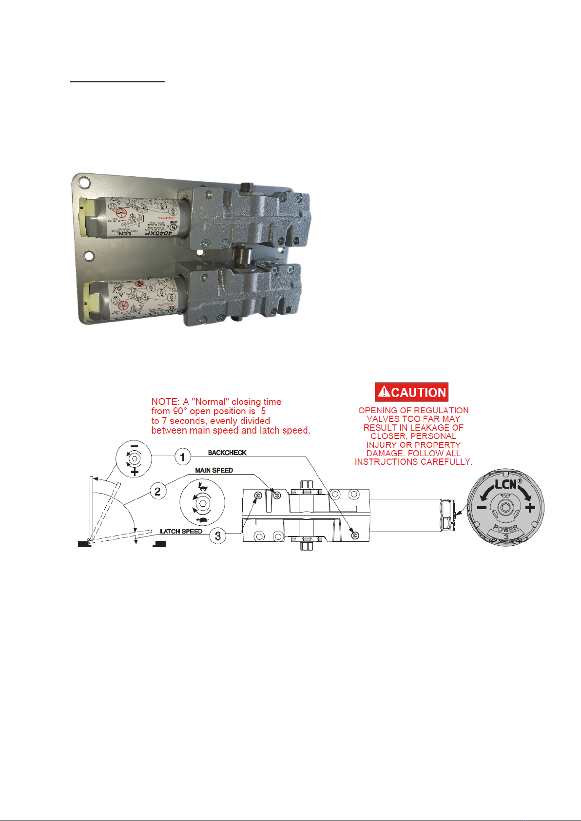
5 – 7 seconds from 90° open to fully closed.
-
When you are happy the closer is installed in accordance with the template and the closer arm has
the necessary pre-
required:
, is located on the end of the spring tube (5/32 Allen key). It is used to
adjust the spring’s power (force to close the door). Clockwise adjustment gives the closer more
-clockwise adjustment gives the closer
reduced closing power and makes the door easier to open.
spaces you must consider combining a number of availabl
-
-
mechanical overhead closer to perform correctly. Similarly, opening windows and doors in connected
-N-Stop arm and
adjust the back check valve (see below) to protect doors and frames.
(*Universal, power adjustable closers only – excludes 2000 series, 3000 series and 4016/4116
closers) (**e)

11
The , (valve #1 -
(3/32 Allen key). Use the back check feature to protect the door, frame and closing mechanism.
Back check slows the door during the opening arc; should it be thrown open or should the wind
the valve clockwise - -clockwise will
give you a weaker back check.
-N-Stop
feature can be used for dead stop angles between 85-
The , (valve #2 -
closed – clockwise will
-clockwise will increase the door’s closing
speed.
The , (valve #3 –
– as the door returns to the frame/stop.
Turning the valve clockwise will reduce the door’s speed to ensure it closes quietly into the frame
-
momentum where required –
–
– i.e.,
and weight parameters do not exceed recommended maximums - will be capable of closing doors in
to
close the door be tempted to ‘over adjust’ speed control valves (valves #2 & #3) to address
the problem. Valves which are backed out to the end of their thread will be dangerously close to
from the mechanism
and the closer will be a write-
closers.
Where there remains any doubt over suitability and/or correct adjustment methods please contact
Relcross Door Controls. We will be pleased to assist wherever possible.
- To adjust any LCN door closer to its - turn all adjustment valves (back
check, main speed, and latch speed valves-
clockwise.
- If the spring force adjustment is set to the very minimum force on 1260 series closers,
the internal spring adjustment plate may rest in a safety area of the threaded spring adjustment rod.
To address this, open the door to approximately 30° to engage the closer spring and turn the power
adjustment screw approximately 6 full turns clockwise.
see here.
Other Relcross Door Controls Door Opening System manuals
Popular Door Opening System manuals by other brands

CLR Jackson
CLR Jackson 400 Series installation instructions

Assa Abloy
Assa Abloy DC130 installation instructions

Nice
Nice STX KIT Instructions and warnings for installation and use

Taurean
Taurean B Series installation instructions

Geberit
Geberit DuoFresh user manual

Mobeye
Mobeye Call-Key MCK100 installation manual

Automatic Technology
Automatic Technology Dominator Tempo ATS-2AM instruction manual

RYTEC
RYTEC Spiral HZ installation manual

Assa Abloy
Assa Abloy Lockwood L7714SDSIL installation instructions

cinetto
cinetto PS23 Assembly instructions

BFT
BFT LUX BT 2B installation manual

Excel
Excel XL8000 Series Installation