ES 200
ES 200
ES 200-2D
ES 200
ES 200
ES 200-2D
DORMA DORMA
Easy Easy
Einweisung:
Nach erfolgreicher Einstellung, Inbetriebnahme und
Funktionsprüfung der Türanlage, ist die Bedienungs-
anleitung dem Betreiber auszuhändigen und eine
Einweisung durchzuführen.
Türverhalten bei unterschiedlichen Witterungsverhältnissen
Die Sicherheitssensoren der Türanlage (Infrarot-
Lichtvorhänge) dienen der Absicherung des
Durchgangsbereichs. Höchste Priorität hat bei der
Einstellung der Empfindlichkeit der Sensoren der
Personenschutz. Insbesondere bei wechselnden
Witterungseinflüssen (Regen- oder Schneeschauern), bei
umherfliegendem Laub oder auch direkter
Sonneneinstrahlung auf reflektierenden Bodenbelägen, kann
es sporadisch zu Fehldetektionen der Sensoren kommen.
Diese haben unter Umständen eine Öffnung der Tür von bis
zu einer Minute zur Folge. Dieser Offenstand der Türanlage
ist durch eine Normvorgabe festgelegt und völlig normal. Er
dient ausschließlich der Sicherheit der Türnutzer.
Wartung
Wartungsarbeiten dürfen nur im spannungsfreien Zustand
durchgeführt werden. Netzstecker ziehen oder bei
Festanschluss Sicherung ausschalten.
Pflege
Reinigungsarbeiten dürfen nur im spannungsfreien Zustand
durchgeführt werden. Netzstecker ziehen oder bei
Festanschluss Sicherung ausschalten.
Die ES 200 , ES 200 und ES 200-2D können mit
einem feuchten Tuch und handelsüblichen Reinigern
gereinigt werden.
Scheuermittel sollten nicht verwendet werden, da sie die
Oberfläche beschädigen könnten.
Lassen Sie kein Wasser oder andere Flüssigkeiten auf oder
in die ES 200 , ES 200 oder ES 200-2D gelangen.
Führen Sie niemals Metallgegenstände in die Öffnungen am
ES 200 , ES 200 oder ES 200-2D ein. Andernfalls
besteht die Gefahr eines elektrischen Schlages.
Verschleiß
Um ein einwandfreies Funktionieren der Anlage zu
gewährleisten muß die Anlage jährlich geprüft werden.
Folgende Verschleißteile müssen geprüft und ggf.
ausgetauscht werden:
·Laufrollen alle 2 Jahre
·Akkublock alle 3 Jahre
·Gummi-Endanschläge bei jedem Servicecheck
·Die Laufschiene alle 5 Jahre
·Den Zahnriemen alle 1 000 000 Lastwechsel
·Die Bodengleiter bei jedem Servicecheck
·Die Bürsten (option) bei jedem Servicecheck
Es dürfen nur Originalersatzteile eingesetzt werden.
Easy
Easy
Easy
Recycling und Entsorgung
Sowohl die
ES 200-2D als auch die Verpackung bestehen
zum überwiegenden Teil aus recyclefähigen
Rohstoffen.
Die ES 200 , ES 200 und ES 200-2D wie
auch das Zubehör gehören nicht in den
Hausmüll.
Sorgen Sie dafür, dass das Altgerät und ggf.
vorhandenes Zubehör einer ordnungsgemäßen
Entsorgung zugeführt werden.
Beachten Sie dabei die geltenden nationalen gesetzlichen
Vorschriften.
Sicherheit bei der Montage
·Der Arbeitsplatz ist gegen unbefugtes Betreten zu
sichern. Herunterfallende Teile oder Werkzeuge
können zu Verletzungen führen.
·Die ES 200 , ES 200 und ES 200-2D müssen vor
Wasser und anderen Flüssigkeiten geschützt werden.
·Befestigungsart und Befestigungsmittel, wie z.B.
Schrauben und Dübel, müssen auf jeden Fall den
baulichen Gegebenheiten angepasst werden
(Stahlkonstruktion, Holz, Beton usw.).
·Die hier beschriebene Montage der ES 200 ,
ES 200 und ES 200-2D sind ein Beispiel. Bauliche
oder örtliche Gegebenheiten, vorhandene Hilfsmittel
oder andere Umstände können eine andere
Vorgehensweise sinnvoll machen.
·Im Anschluss an die Montage sind die Einstellungen
und die Funktionsweise der ES 200 , ES 200 und
ES 200-2D und der Schutzeinrichtungen auf
einwandfreien mechanischen Zustand zu überprüfen.
·Nur qualifizierte Fachleute dürfen das
Netzanschlussgehäuse öffnen.
·Vor Abnahme der Schutzhaube den ES 200 ,
ES 200 oder ES 200-2D spannungsfrei schalten.
Netzstecker ziehen oder, bei Festanschluss, Sicherung
ausschalten.
·Fassen Sie das Netzkabel nur am Stecker und niemals
am Kabel an, um es aus der Steckdose zu ziehen.
Sicherheit bei der Inbetriebnahme
·Der Schutzleiter muss angeschlossen sein.
·Die Sicherheitssensorik soll angeschlossen sein
(siehe Inbetriebnahmeanleitung).
·Antriebseinheit und Fahrflügel sind Korrekt
miteinander verbunden
·Die Endanschläge sind so eingestellt, dass die
Fahrflügel bei max. Öffnungsweite die Endanschläge
berühren. Die Fahrflügel und die Standflügel bei
geschlossener Tür nicht mit den Dichtungsprofilen
zusammenstoßen.
·Fahrflügel müssen leichtgängig sein.
·Die separat gelieferten Teile wie Programmschalter,
NOT-AUS Schalter und Impulsgeber, (Radarmelder,
NACHT/BANK-Schlüsseltaster) müssen montiert und
angeschlossen sein.
·Akkueinheit ist eingebaut (optional)
Überprüfung und Abnahme
Die ES 200 , ES 200 und ES 200-2D st vor der ersten
Inbetriebnahme und nach Bedarf, jedoch mindestens
einmal jährlich, von einem Sachkundigen zu prüfen und ggf.
zu warten.
Die Überprüfung und Abnahme müssen anhand des
Prüfbuchs von einer durch DORMA ausgebildete Person
durchgeführt werden.
Die Ergebnisse sind gemäß DIN 18650-2 zu dokumentieren
und für mindestens 1 Jahr durch den Betreiber
aufzubewahren.
Es empfiehlt sich mit DORMA einen Wartungsvertrag
abzuschließen.
ES 200 , ES 200 undEasy
Easy
Easy
Easy
Easy
Easy
Easy
Diese Dokumentation enthält wichtige Anweisungen für die
Montage. Lesen Sie diese Anweisungen, bevor Sie den
200 , ES 200 oder ES 200-2D montieren.
Für Ihre Sicherheit ist es wichtig, allen beiliegenden
Anweisungen Folge zu leisten.
Eine falsche Montage kann zu schwerwiegenden
Verletzungen führen.
Die Verwendung von Steuerelementen, Einstellungen oder
Verfahren, die in dieser Dokumentation nicht beschrieben
sind, können elektrische Schläge, Gefahren durch
elektrische Spannungen/Ströme und/oder Gefahren durch
mechanische Vorgänge verursachen.
Die Unterlagen sind aufzubewahren und bei einer
eventuellen Weitergabe der Anlage mit zu übergeben.
In dieser Anleitung benutzte Symbole
WICHTIG Dieses Piktogramm macht auf wichtige
Informationen aufmerksam, die Ihnen
die Arbeit erleichtern,
warnt vor möglichen Beschädigungen
des Gerätes und erläutert, wie diese
verhindert werden können und
weist auf Gefahren hin, die zu
Sachschäden, Personenschäden oder
zum Tod führen können.
Bestimmungsgemäßer Gebrauch
Der ES 200 dient ausschließlich zum Öffnen und
Schließen von Schiebetüren mit einem zulässigen
Türflügelgewicht bis zu 1 x 100 kg oder 2 x 85 kg.
Der ES 200 ist nicht zur Verwendung in
Rettungswegen, an Brandschutztüren (Feuer-
/Rauchschutztüren) und im Außenbereich geeignet.
Der ES 200 dient ausschließlich zum Öffnen und Schließen
von Schiebetüren mit einem zulässigen Türflügelgewicht
bis zu 1 x 200 kg oder 2 x 160 kg.
Der ES 200 ist nicht zur Verwendung an Brandschutztüren
(Feuer-/Rauchschutztüren) und im Außenbereich geeignet.
Der ES 200-2D dient ausschließlich zum Öffnen und
Schließen von Schiebetüren mit einem zulässigen
Türflügelgewicht bis zu 1 x 150 kg oder 2 x 130 kg.
Der ES 200-2D ist für den Einsatz in Flucht- und
Rettungswegen geeignet.
Der ES 200-2D ist nicht zur Verwendung an
Brandschutztüren (Feuer-/Rauchschutztüren) und im
Außenbereich geeignet.
Die maximale Kabellänge externer Komponenten darf 30 m
nicht übersteigen.
Haftungsbeschränkung
Die ES 200 , ES 200 und ES 200-2D dürfen nur
gemäß ihre bestimmungsgemäßen Verwendung eingesetzt
werden. Eigenmächtige Änderungen am ES 200 ,
ES 200 oder ES 200-2D schließen jede Haftung durch die
DORMA GmbH + Co. KG für daraus resultierende Schäden
aus. Für die Verwendung von Zubehör, das von DORMA
nicht freigegeben ist wird keine Haftung übernommen.
Sicherheitshinweise
Arbeiten an Elektroanlagen dürfen nur von geschulten
Fachkräften (Elektriker) ausgeführt werden.
·Kinder nicht mit dem ES 200 , ES 200,
ES 200-2D oder fest montierten Regel- und
Steuereinrich-tungen spielen lassen. Fernsteuerungen
außerhalb der Reichweite von Kindern halten.
·Führen Sie niemals Metallgegenstände in die
Öffnungen des ES 200 , ES 200 oder ES 200-2D
ein. Andernfalls besteht die Gefahr eines elektrischen
Schlages
·Für Glastürflügel muss Sicherheitsglas verwendet
werden.
ES
Easy
Easy
Easy
Easy
Easy
Easy
Easy
Wichtige technische Daten
ES 200 , ES 200 ES 200-2D
·Spannungsversorgung 230
·Bauseitige Absicherung 16 A
·Betriebsgeräusch < 70 dB(A)
Normen, Gesetze, Richtlinien und Vorschriften Allgemeines
·Der neueste Stand der allgemein gültigen und länder-
spezifischen Normen, Gesetze, Richtlinien und
Vorschriften ist einzuhalten.
DIN 18650
Der Hersteller (die Person, die den Einbau vornimmt) und
der Auftraggeber/Betreiber müssen bei der Planung der
Anlage gemeinsam eine individuelle Risikobeurteilung
durchführen.
Wir verweisen hierzu auf das zur Unterstützung der
Durchführung zur Verfügung stehende Formular
"Risikobewertung", Sie erhalten es unter dem Register
PRODUKTE auf unserer Internetseite www.dorma.de.
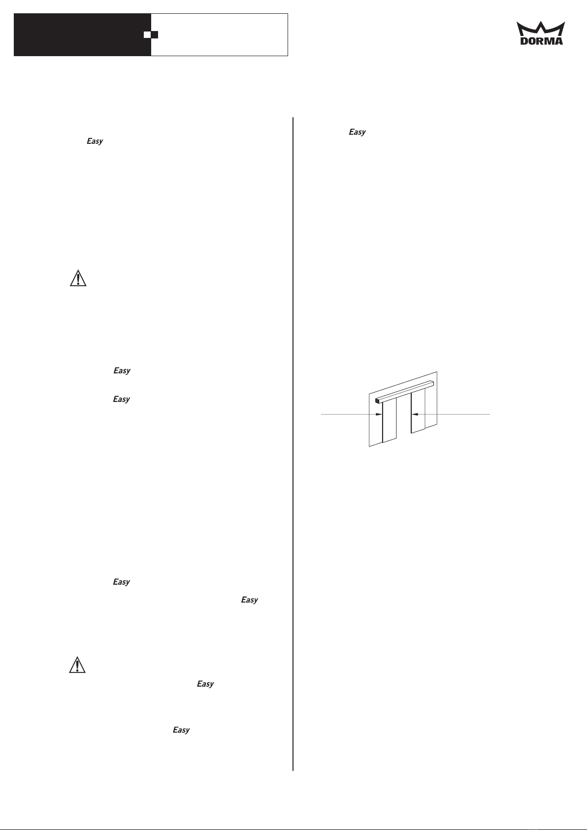
Gefahrenstellen an Schließkanten
An automatischen Türen können an den verschiedenen
Schließkanten Quetsch-, Scher-, Stoß- und
Einzugsgefahren bestehen.
Restrisiko
Je nach baulicher Gegebenheit, Türvariante und
Absicherungsmöglichkeit können Restgefahren (z. B.
Quetschen, kraftbegrenztes Anstossen) nicht
ausgeschlossen werden.
Easy
·Zul. Luftfeuchtigkeit: 93% rel. Feuchte,
nicht kondensierend
·Zul. Betriebstemperatur -20°C bis 60°C
Haupt-
schließkante
Neben-
schließkante
1. Zu Ihrer Sicherheit