Relcross Door Controls 9130 User manual

9130/9140 Series
Low Energy Swing Operator
UK Installation Instructions
rev 11/21

CONTENTS
1
GENERAL
2
2
PRE-INSTALLATION & PRODUCT CHECK
3
3
OPERATOR INSTALLATION
4
4
WIRING
5
5
ARM & COVER INSTALLATION
6
6
OPERATOR ADJUSTMENT
7
7
FUNCTION TABLES & WIRING DIAGRAMS
10
8
RELEASE FOR SERVICE
15
1/15

1
GENERAL
The 9130/9140 series is an automatic electro-mechanical swing door
operator for use on hinged, centre pivoted and offset pivoted doors.
The controller is a microprocessor based system, tracking the door position
at any time during the cycle. When activated the operator drives the door
to the full open position creating potential energy in the spring.
When closing,the electrical power is reduced and the door closes by
controlling the potential energy release in the spring force.
The activating circuit opens the door from any position on the closing
swing. During power failure the operator acts as a manual door closer
(size 3). Door opening and closing cycles, including opening speed,
back check speed, hold open time delay, closing speed, and latch position
are all adjustable.
CAUTION
Always disconnect mainspower to the
operator prior to servicing or cleaning
2/15

2PRE-INSTALLATION & PRODUCT CHECK
2.1 Check the product model is correct for the required application.
2.2 Check all parts listed for the installation are received.
2.3 Check architectural drawings and final approved shop drawings
for position of frame and structural openings.
2.4 Check header and frame dimensions and required clearances (see below).
2.5 Ensure door weight does not exceed 90kilos
2.6 Check that a 240 Volt, single phase, 50 Hz, fused supply (5 amp fuse
maximum) is available adjacent to the door - preferably
150mm above the pivot point on the operator side
2.7 If an electric lock is to be connected to the system the
maximum current draw is 2 Amps. The switching relay contact is
a maximum resistive current of 2 Amps.
2.8 The supply must be a dedicated circuit from the main circuit
breaker panel and must not be connected into building
lighting circuit with fluorescent lights.
2.9 When Pre-Install & Product Check is complete
go to: 3 OPERATOR INSTALLATION.
Clearances for Pull System Clearances for Push System
3/15

3 OPERATOR INSTALLATION
3.1 Remove the control box then the motor from their mounting brackets.
3.2 Prepare the header frame for push or pull system (see below).
3.3 Install the operator-mounting bracket onto the header/frame.
3.4 Re-install the motor then the control box onto their mounting brackets.
3.5 When the operator installation is complete go to 4 WIRING.
Header Frame & Door Preparation: Push System
REVEAL DIM A: Butt-Hung or Offset Pivot DIM A: Centre Pivot
25mm 559mm 686mm
51mm 533mm 660mm
76mm 508mm 635mm
102mm 483mm 610mm
127mm 457mm 584mm
152mm 457mm 584mm
NOTE: For push units with a reveal greater than 152mm you will need
to purchase an extended arm
Header Frame & Door Preparation: Pull System
129
49
37
3
660
440
220
Ø22
HIGH VOLTAGE
CONDUIT
DIM A
22
129
49
16
3
660
440
220
Ø22
HIGH VOLTAGE
CONDUIT
704
22
29
Relcross Door Controls | E: [email protected] | T: 44(0)1380 729600Relcross Door Controls | E: [email protected] | T: 44(0)1380 729600
4/15

4
WIRING
CAUTION
Make sure all wires are properly dressed and secured to
prevent interference
Route all wiring away from moving parts, sharp edges
and heat sources
Use copper conductors only
Do not modify the factory wiring or connect into existing
electrical circuits or devices
4.1 Refer to the appropriate wiring diagram for the standard control box (Page
13) or the diagram supplied for custom applications. Connect the
following cables:
- Ground cable (ground the operator properly with the earth from the
mains supply)
- Hall effect cable (do not wrap the hall effect cable around the motor
cable)
- Motor power cable (do not wrap the motor cable around the hall-effect
cable).
- Control box power cable
4.2 Connect activation and safety devices + operational keyswitch and lock
accessories if applicable. Refer to the accessory instructions for any
accessories used. Do not connect any remote activating device to the door
unless it is located within line of sight of the door.
4.3 When the wiring is complete go to
5 ARM & COVER INSTALLATION.
5/15

5
ARM & COVER INSTALLATION
CAUTION
Keep hands, clothing, wires, tools, etc. away from the
operator motor when the operator is turned on
5.1 Make sure the operator power switch is turned OFF.
5.2 Install a jumper across the control box MAIN ACT T28 and COMMON T27.
5.3 Turn the operator power switch on. The operator motor will activate and
drive to the full open position.
5.4 Attach the arm to the operator spindle loosely with the 8-mm socket head
screw (for push systems ensure the adjusting boss is inserted correctly).
5.5 Attach the arm to the door:
5.5.1 For push systems attach the push arm shoe to the door.
5.5.2 For pull systems, slide the pull arm roller into the track, insert a track
cap on each end of the track, and attach the track to the door.
Push Arm
Pull Arm
5.6 Adjust the arm:
5.6.1 For pull systems, remove the locking screw from the arm.
5.6.2 For the push system remove the locking screw from the arm.
5.6.3 Keep the door in the full open position and adjust the arm length as
necessary to align the door at 90 degrees from closed. When the arm
is adjusted to the correct length, tighten up the 8 mm socket head
screw that secures the arm to the operator spindle (ensure this
is secure) and then tighten the arm locking screw.
5.7 Turn off the power operator switch - the door closes.
5.8 Remove the jumper from the control box T27, T28.
5.9 When arm installation is complete go to 6 OPERATOR ADJUSTMENT
6/15

6
OPERATOR ADJUSTMENT
CAUTION
If the encoder is connected in the opposite direction, disconnected or
faulty the door will operate erratically (continuously opening halfway,
closing, latching and reopening etc.). This will continue until power is
switched off and problem rectified.
6.1 SETTING FUNCTION
6.1.1 From the FUNCTION SELECTOR switch to one of the 6 standard
program settings depending on the desired fire alarm position AND
monitored safety requirement (see FUNCTION table on page 11). If
no safety devices are to be used then only the fire alarm position is
critical.
6.1.2 For function 0, 3 & 6 (i.e. fail safe to open position) Fire Alarm input
operates the door and it remains in the open position for as long as
the contact is made.
6.1.3 For function 1, 4 & 7 (i.e. fail safe to closed position) Fire Alarm input
disables all activation allowing the door to close where it remains for
as long as the contact is made.
6.2 LEARNING CYCLE & SET UP (no safety sensors)
6.2.1 From start-up, the door will activate from either T9 & T10 (Fire Alarm)
or T27 & T28 (One Way). Activate the operator using the activation
device - the operator will perform one learning cycle. During the
learning cycle, the door opens and closes one time.
6.2.2 The speed of the learning cycle is adjusted automatically to
compensate for the door weight and is not set from a potentiometer.
6.2.3 The door drives to the fully open position where the control box sets
the parameters to the fully open setting (NB - remember to install
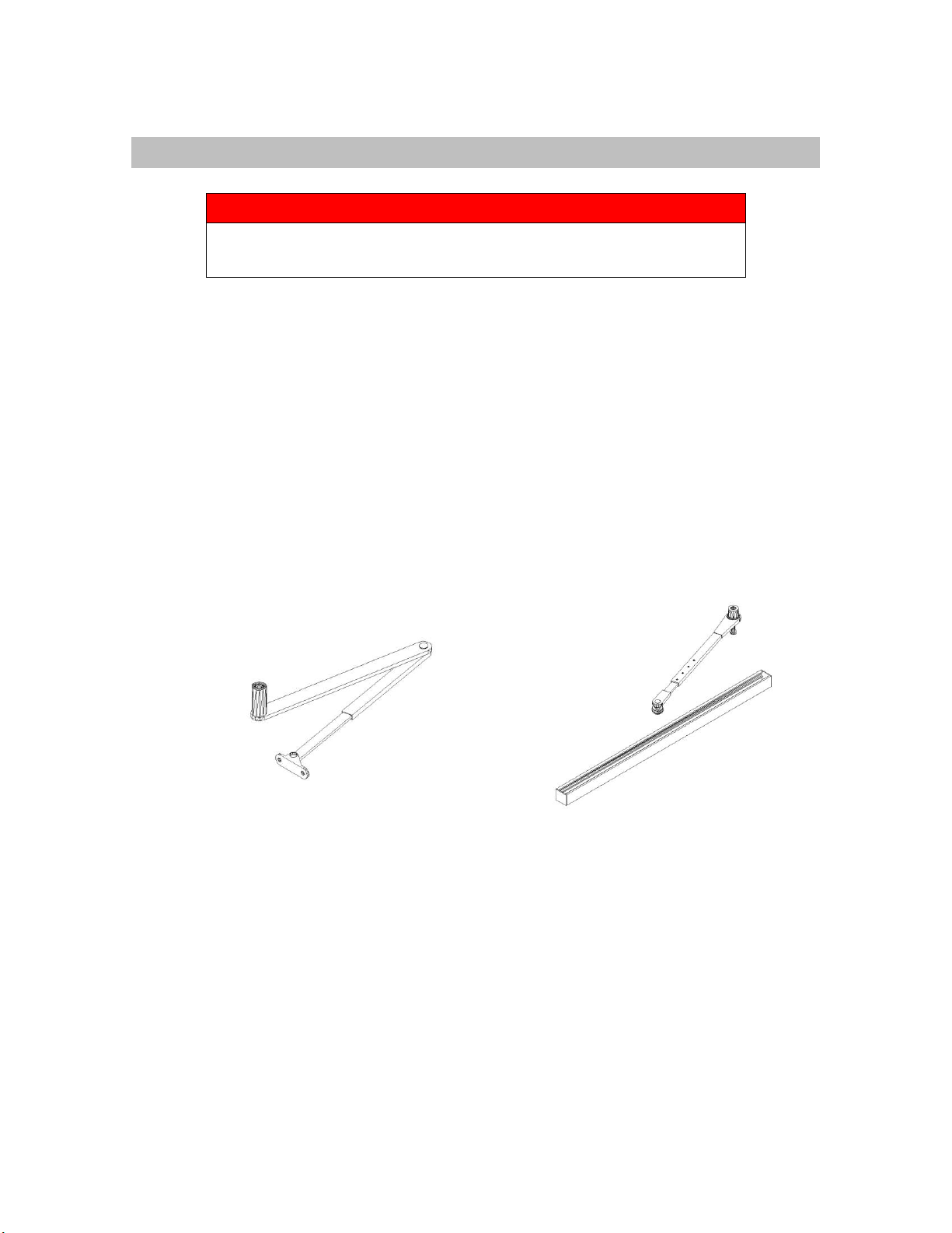
drive arm when door is in the open position).
6.2.4 When the door reaches the fully open position the control box
automatically sets the power required to keep the door open until
activation and/or timer is cleared
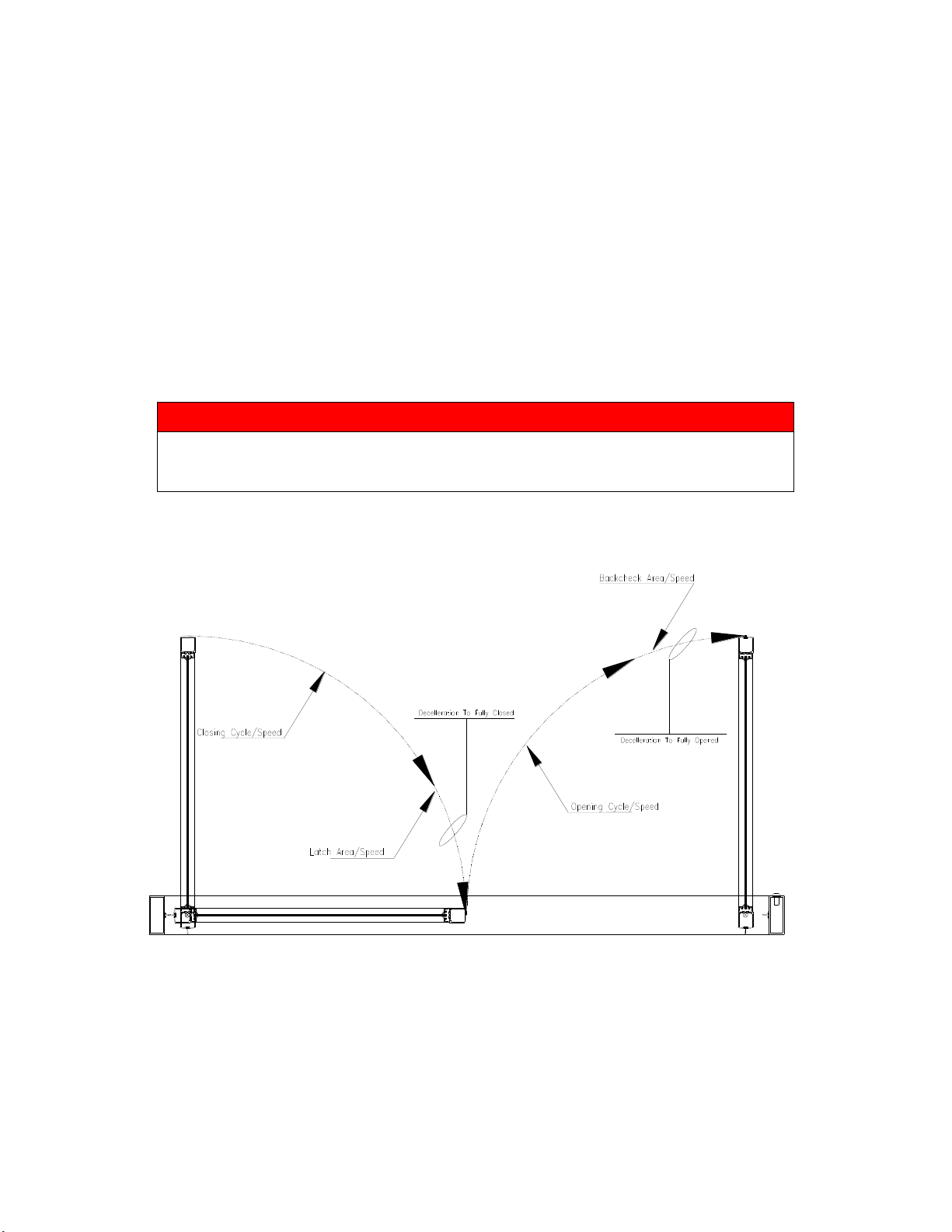
6.2.5 The door closes at the designated close speed (P6) up to latch
position (P5) where the speed is decreased automatically by the
control box allowing the door to close smoothly until fully closed.
6.2.6 If the door does not open at all during learning cycle:
- Check the door for binding.
7/15

- If an electromechanical lock is being used, check that the lock
disengages before the operator opens the door.
- Check fuses, circuit breakers and connections.
- Adjust the operator and check door operation.
Opening speed 75%
Back check speed 75%
Hold open time delay Minimum
Latch position Maximum
Closing speed 50%
SW 1,2,3,4 OFF
6.2.7 If the door does not open fully during learning cycle:
- Check the door for binding.
- Increase the back-check speed slightly and check door
operation. Continue increasing back-check speed until door
opens fully.
6.2.8 If the door slams open decrease the back check speed slightly (P2)
and check door operation. Continue decreasing back check speed
until the door opens without slamming.
6.2.9 After the learning cycle is complete and the door is closed, apply a
maintained activation signal and check that the door remains open
while the signal is applied.
6.3 AUTO REVERSE
6.3.1 The door will auto reverse back to the open position
if an obstruction is present
6.3.2 P4 sets the level of torque required to trip the door as it is opening so
that it automatically reverts to the closed position
6.4 SAFETY SENSORS
6.4.1 Door Safety Opening:
Firstly, when the door is in the closed position, activate the safety
device (T1 & T2) then try to activate the door. The door should remain
closed
Secondly, activate the door and as it is opening activate the safety
device. The door should stop and then slowly drive to the fully
opening position
The point at which the safety device becomes inactive can be
adjusted via P8 from closed position up to back check position
8/15

6.4.2 Door Safety Closing:
Firstly, activate the door to the full open position then activate the
safety device (T5 & T6). The door should remain open.
Secondly, activate the door and as it is closes activate the safety
device. The door should stop and then re-open slowly to the fully
open position, time out and close.
The point at which the safety device becomes inactive can be
adjusted via P7 from open position up to a few degrees of closed
position
NOTE
Adjust operator in accordance with EN16005 be it for power assisted
low energy power operated doors
9/15

7
FUNCTION TABLES & WIRING DIAGRAMS
See table and diagrams that follow for operator feature selection and
adjustments. After adjustment, cycle the door several times and check for proper
operation. Then go to 8 RELEASE FOR SERVIVE.
N
7.1 CONTROL BOX: POTENTIOMETERS & SWITCHES
7.4OTE
ON
OFF
POWER BOOST ADJ
CONT
5 SECS
SW4
POWER BOOST ACT
ON
OFF
SW3
PUSH & GO
ON
OFF
SW2
MONITORED SAFETY
ON
OFF
SW1
10/15

7.2 CONTROL BOX: FUNCTIONS
FUNCT.
PROGRAM
DESCRIPTION
MONITORING
TERMINAL
OPERATION
0
Standard
Standard functionality and
adjustment - door to failsafe open on
fire alarm
Safety: Opening &
Closing
T1, T2
Door Safety Opening
T5, T6
Door Safety Closing
T9, T10
Fire Alarm
1
Fire Alarm
Standard functionality and
adjustment - door to failsafe closed
on fire alarm and remain electrically
unlocked (if locking present)
T27, T28
One Way
T14
Door Open
T12
Key Switch Off
2
WC
BESPOKE SOLUTION - ALLEGION
T22, T23
Two Way
3
Standard
Standard functionality and
adjustment - door to failsafe open on
fire alarm
Safety: Opening
Only
T1, T2
Door Safety Opening
T5, T6
Door Safety Closing
T9, T10
Fire Alarm
4
Fire Alarm
Standard functionality and
adjustment - door to failsafe closed
on fire alarm and remain electrically
unlocked (if locking present)
T27, T28
One Way
T14
Door Open
T12
Key Switch Off
5
WC
BESPOKE SOLUTION - ALLEGION
T22, T23
Two Way
6
Standard
Standard functionality and
adjustment - door to failsafe open on
fire alarm
Safety: Closing
Only
T1, T2
Door Safety Opening
T5, T6
Door Safety Closing
T9, T10
Fire Alarm
7
Fire Alarm
Standard functionality and
adjustment - door to failsafe closed
on fire alarm and remain electrically
unlocked (if locking present)
T27, T28
One Way
T14
Door Open
T12
Key Switch Off
8
WC
BESPOKE SOLUTION - ALLEGION
T22, T23
Two Way
9, A-F
NOT IN USE
A
B
C
D
E
F
11/15

7.3 CONTROL BOX: SETTINGS
Features
Control
Description
Anti-Clockwise
Clockwise
Opening
Speed
P1
Controls opening speed of door
Slower
Faster
Back Check
Speed
P2
Controls speed of door near full open
position prevent door slamming
Slower
Faster
Hold Open
Time Delay
P3
Controls length of time door remains
in the full open position
Less time
(min 1 sec)
More time
(max 30 sec)
Auto Reverse
Setting
P4
Sets pressure required on door
opening before door stops
Less pressure
required
More pressure
Required
Latch
Position
P5
Distance at which the door begins to
decelerate to fully closed position to
prevent door slamming
Less latch
More latch
Closing
Speed
P6
Controls closing speed of door
Slower
Faster
Safety
Opening
Angle
P7
Controls the angle during the open
cycle that safety operates
Closer to closed
position
Further from
closed position
Safety
Closing
Angle
P8
Controls the angle during the close
cycle that safety operates
Closer to open
position
Further from
open position
Monitored
Safety
SW1
To allow monitoring of safety sensors
Monitoring
‘ON’
Monitoring
‘OFF’
Push & Go
SW2
Pushing the door open by 5° causes
the operator to open for the remainder
of the open cycle
Push & Go
‘ON’
Push & Go
‘OFF’
Power Boost
Activation
SW3
Power boost gives a force in the
closed direction when the door is
closed - used for high wind situations
Power Boost
‘ON’
Power Boost
‘OFF’
Power Boost
Adjustment
SW4
Enables power boost to operate
continuously or for 5 seconds only
after the door closes
Continuous
5 Seconds
12/15

7.4 WIRING DIAGRAM INCLUDING TERMINALS
13/15

8
RELEASE FOR SERVICE
8.1 Snap the optional end cap insert into the end cap opposite the on/off
switch.
8.2 Install the cover assembly onto the operator.
8.3 Remove all installation equipment and debris from the vicinity of the door.
8.4 Install all safety, traffic control and instruction labels on the door as
required under EN16005. Failure to do this leaves the installer LIABLE for
any accident that might occur - this must be done.
8.5 Instruct the owner or person in charge of the proper operation of the door.
8.6 Instruct the owner or person in charge to routinely inspect the door for the
following:
- Occasional damage
- Developing problems
- Minor preventative maintenance
8.7 Instruct the owner or people in charge who and where to call for service
and maintenance when required.
IMPORT
IMPORTANT
Make sure to install all safety, traffic control
and instruction decals on the door as required
15/15
Other manuals for 9130
2
This manual suits for next models
1
Table of contents
Other Relcross Door Controls Gate Opener manuals