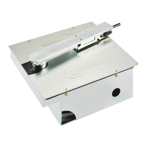
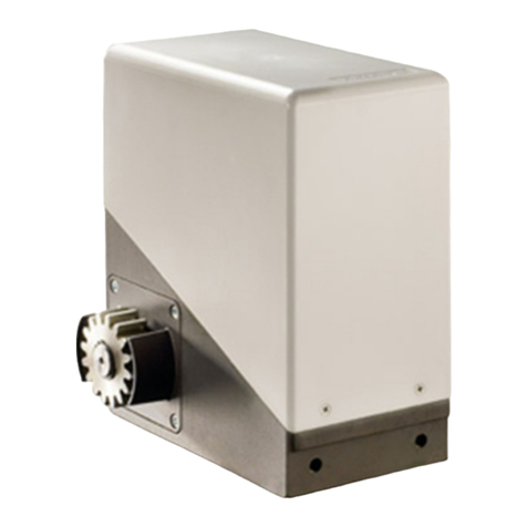
Erreka KAIROS User manual
Other Erreka Gate Opener manuals

Erreka
Erreka ARES Series User guide
Erreka
Erreka SIRIUS Operating instructions
Erreka
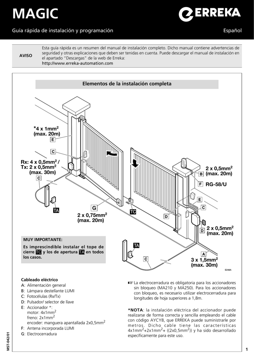
Erreka MAGIC Operating instructions

Erreka
Erreka VULCAN D User manual

Erreka
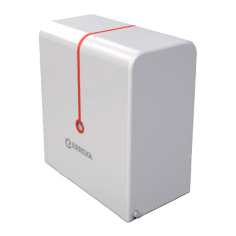
Erreka Fenix User guide
Erreka
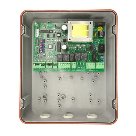
Erreka DINGO Operating instructions
Erreka
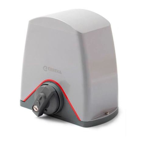
Erreka VIVO-M101 Operating instructions
Erreka
Erreka Puma Operating instructions

Erreka
Erreka DINGO Operating instructions

Erreka
Erreka CICLON Operating instructions

Erreka
Erreka ARES User guide
Erreka
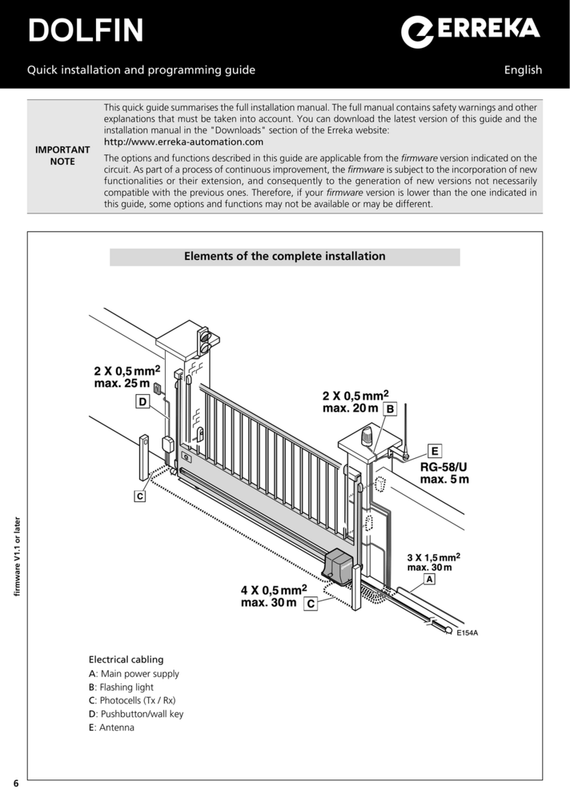
Erreka Dolfin Operating instructions
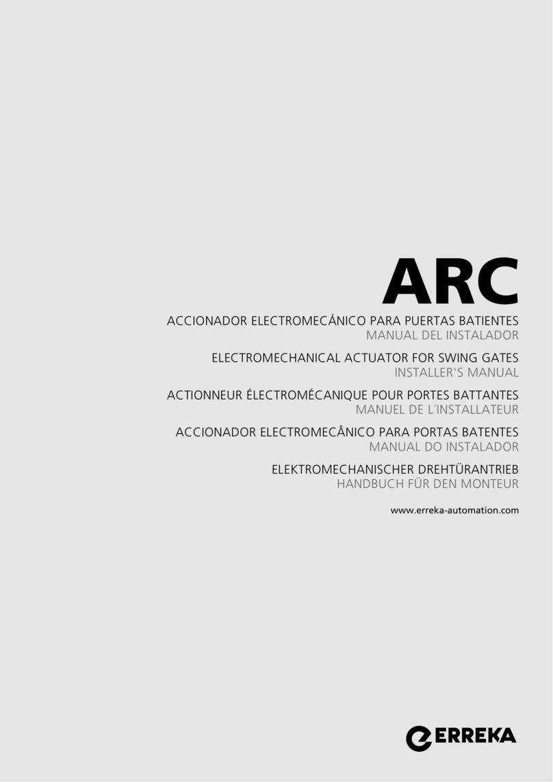
Erreka
Erreka ARC Series User guide
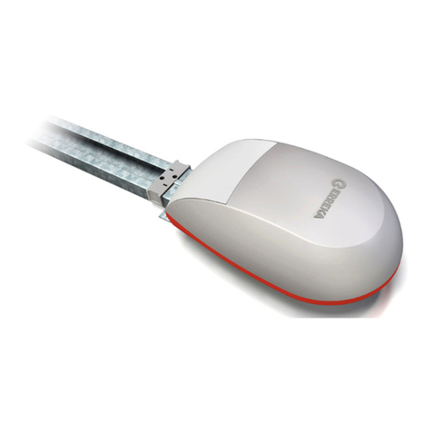
Erreka
Erreka NAOS Operating instructions
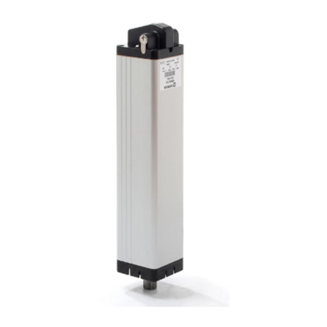
Erreka
Erreka V2 CICLON User manual
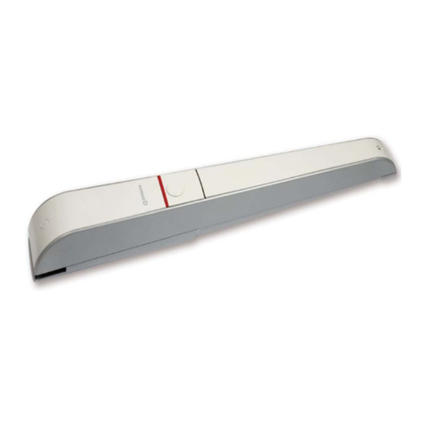
Erreka
Erreka AXIL Operating instructions
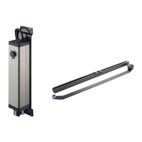
Erreka
Erreka CICLON Series User manual

Erreka
Erreka VIVO-M201M Operating instructions

Erreka
Erreka VULCAN S User manual
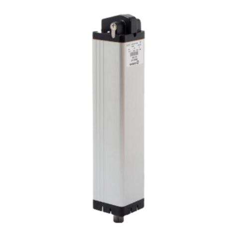
Erreka
Erreka MAGIC User guide
Popular Gate Opener manuals by other brands

Comunello Automation
Comunello Automation ABACUS 220 Installation and user manual

CAME
CAME FA40230CB installation manual

Mighty Mule
Mighty Mule 200 E-Z GATE OPENER UL325 SERIES installation manual

Riello Elettronica
Riello Elettronica CARDIN ACE FAST Instruction handbook

Telcoma
Telcoma ARM Instruction handbook
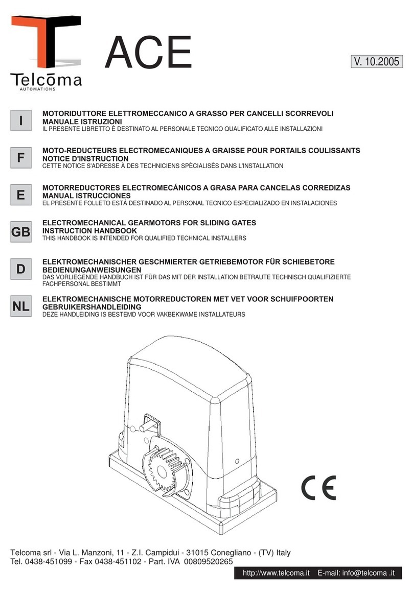
Telcoma
Telcoma ACE Instruction handbook


