manuals.online logo
Brands
  1. Home
  2. •
  3. Brands
  4. •
  5. DKS
  6. •
  7. Gate Opener
  8. •
  9. DKS 9200 "Full Open" User manual

DKS 9200 "Full Open" User manual

Anti-Grounding Plate
TIME
DELAY
EXIT
LOOP
LMT
REVERSE
LOOP
REV SENSE
OPEN
REV SENSE
CLOSE
1
ON
2 3 41
ON
2 3 4 5 6 7 8
NC
NO
P8 P7P6
4404-010
20 19 18 17 16 15 14 13 12 11 10 987654321
94109410
1
2
5
6
11
13A
13B
13E
25
16
17
U
L1 L2/N B- B+
VWPE PE
Mode
EPM
1.0
PE
SCM series
basic I/O control
115 VAC Convenience Outlets
DO NOT power up and
cycle the operator until
the “DIP-Switches” and
the “Limit Switches”
have been adjusted.
Damage could occur to
the gate and operator.
T
T
T
T
T
T
T
T
T
Opening
direction
OFF setting.
Opening
direction
ON setting.
Tip: It is recommended that a surge suppressor be installed on the high voltage
power lines.
GATE OPERATOR MUST BE PROPERLY GROUNDED!!
CAUTION
High Voltage AC input power MUST MATCH
the operator specifications or DAMAGE will
occur and VOID the warranty!
VERIFY Input AC power MATCHES your
specific operator power BEFORE wiring!
EXIT
LOOP
LMT
REVERSE
LOOP
REVSENSE
CLOSE
P8 P7
P6
4404-010
12
43
12
43
12
43
Electronic Box
Power safety and opening devices
that require 115 VAC power.
Two 115 VAC Convenience Outlets
Model 9200 is intended for installation only on sliding gates used for vehicles.
Pedestrians must be supplied with a separate access opening. For safety and installation instructions,
please refer to the Installation/Owner’s manual.
See reverse side
See reverse side to wire main terminal.
With power OFF, push and hold the
lock plate down where shown to
adjust the Open and Close limit nuts.
After adjusting the limit-nuts, be sure
that the lock-plate is engaged in the
slots on the limit-nuts to prevent them
from rotating.
The slow-down limits on all models
but the 9210 will move up or down
3/4 inch. DO NOT remove the
slow-down limit assembly from the
3/4 inch slot and re-attach it in the
longer slot on the partial open
adjustment rail to gain further
adjustment. This will cause mechani-
cal damage to the switch assembly
when the operator is activated.
Turn power ON and activate the gate
operator. Re-adjust the limit nuts as
necessary for full-open and full-close
gate travel. After you are satisfied with
the gate limit settings, the speed
control knob can then be adjusted on
all models but the 9210 to personal
preference.
4” Min.
Pad depth is determined by soil conditions and local building codes.
Minimum depth is 18 inches. Reinforced concrete recommended.
Concrete Pad
Wire
Mesh
3/4”conduit with
sweeps recommended.
Clear Plastic Electronic Box Cover
1
2
3
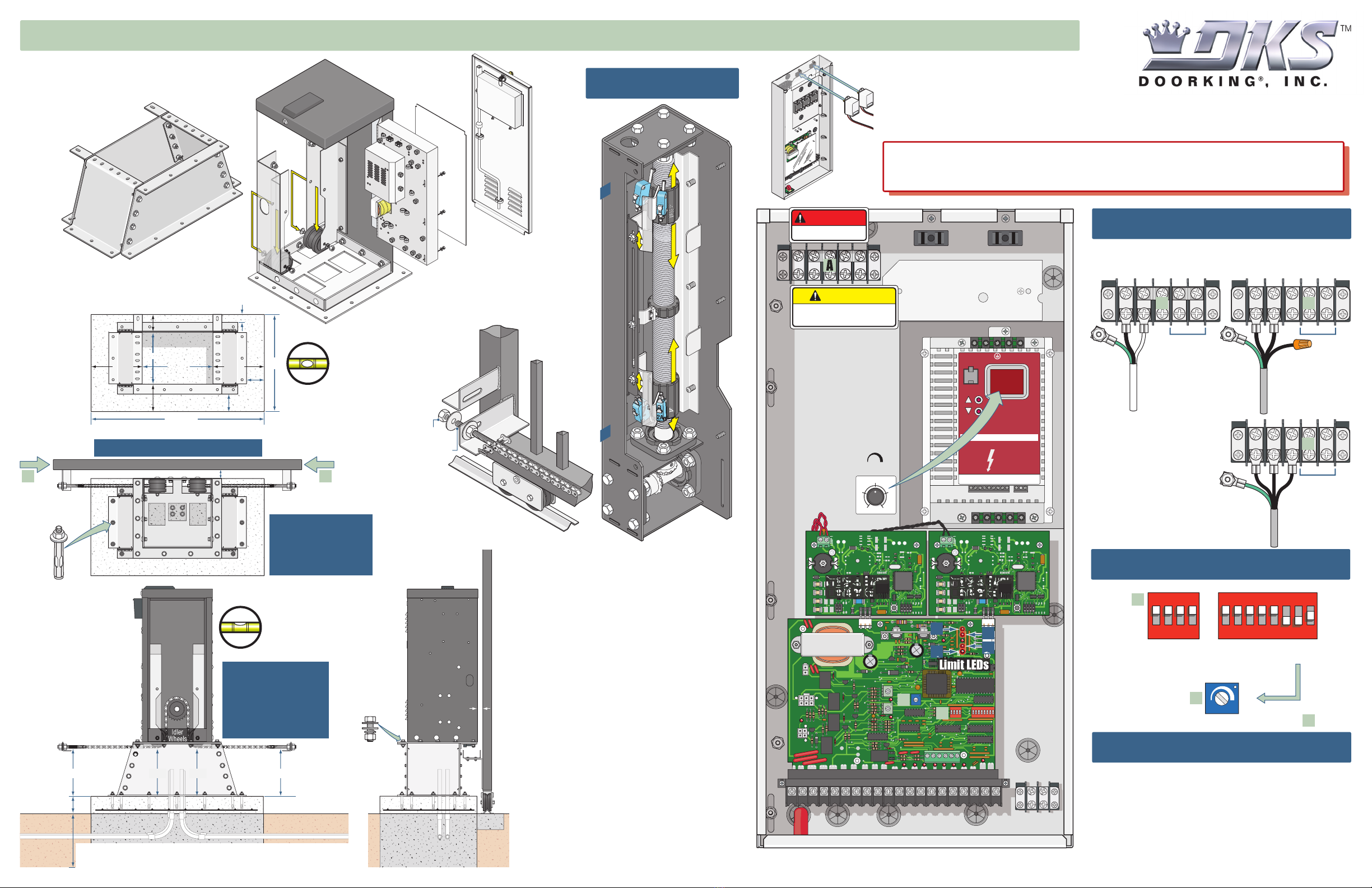
QUICKSTART “BASIC” GUIDELINES FOR MODEL 9200 “FULL OPEN”: MOUNTED ON THE PEDESTAL MOUNTING STAND
120 Glasgow Avenue
Inglewood, California 90301
U.S.A.
Copyright 2013 DoorKing, Inc. All rights reserved. 9240-066-E-2-13
Plug-In Loop Detectors
Not included - Refer to the Installation/Owner’s manual AND
Loop Information Manual (available from www.dkaccess.com)
for more information on loops and plug-in loop detectors.
Important Note: DoorKing highly recommends that loops and
loop detectors are installed with this slide gate operator. A loop
detection system will preventing the gate from automatically
opening or closing on a vehicle when it is in the gate’s path.
High Voltage Connection
DIP-Switches
Limit Switches
1. Opening Direction
2. ON
3. ON
4. OFF
5. OFF
6. OFF
7. OFF
8. OFF
1. OFF
2. OFF
3. OFF
4. OFF
Auto-Close Timer
Chassis
Ground
DANGER
HIGH VOLTAGE!
1
ON
2 3 4 5 6 7 8 1
ON
2 3 4
SW 1 and 2 are Upside-Down on Circuit Board.
123
TIME
DELAY
A
B
D
C
C C
B
D
1 ft/s
.5 ft/s
0 ft/s 2 ft/s
1.5 ft/s
Limit LEDs
Plug-In Loop
Detector Plug-In Loop
Detector
MinMax
Speed
Push Push
Lock-Plate
Limit Nut Limit Nut
1
2
1
2
2
2
2
Slow-Down Limit
Slow-Down Limit
1A
2A
Partial Open
Not Used
1
2
2A
1A
Adjust 1 to 23 sec.
1 Limit
Switch
2 Limit
Switch
Check polarity of Three Phase:
Position the gate half way open.
Give open command and while
gate is opening, activate the
appropriate limit switch with your
finger. Gate should STOP. If it does
not, activate the other limit switch.
If this STOPS the gate, AC power
wires must be changed (Reverse
the connection of any 2 wires and
re-check limits).
Partial Open Adjustment Rail
208/230 VAC
THREE Phase
Chassis
Ground High
Voltage
AC Input
Wire
Hot
115 VAC Output
HotHot
208/230 VAC
SINGLE Phase
Chassis
Ground
High
Voltage
AC Input
Wire
Hot
115 VAC Output
Hot Hot
Use only two legs
of the incoming
3-phase power.
Chassis
Ground
High
Voltage
AC Input
Wire
Hot
115 VAC Output
Neu
115 VAC
SINGLE Phase
White - Neutral
Black - 115 VAC Hot
Green - Chassis
Ground
SW 1SW 2
AA
A
Operator MUST be parallel to gate!
Chain brackets MUST
align with idler
wheels so chain
stays parallel to gate!
Remove the 3 locknuts inside the
electronic box to swing box open.
Gain Access Inside Operator
Move the idler wheels to the lower position.
Fits on All 9200 Models.
Standard with 9230, 9235, 9240 and 9245 Models
1/2
Attach pedestal stand with
sixteen (16) 1/2” x 3” sleeve
anchors (not supplied) after
concrete pad has been
poured and has cured.
Bolt operator to
pedestal with
hardware supplied
in pedestal kit.
Manual
crank in
stored
position.
Caution:
Never
attempt to
manually
operate the
9200 until
you have
verified that
power has
been shut-off.
Connect
Chain to
the Gate
Chain nut
and chain bolt
should not protrude
past gate frame. The chain
should sag no more than one
(1) inch per 10 feet of travel. Do not
over tighten the chain.
Chain
Nut
Chain Bolt
Option 2
Master Link
Option 1
Gate
Frame
1”
Assemble Pedestal
Mounting Stand
Concrete Pad
Dimensions,
Pedestal
Mounting
Stand and
Conduit
Positions
1.75”
11.75”
4”
6.25” 4”
4”
Concrete Pad
Conduit
Area Concrete pad
MUST be level!
Idler
Wheels
Gate
Chain
Bracket
Conduit
Chain
Bracket
Chain
Bracket
Idler Wheels
Chain
Configuration
Concrete Pad
Electronic Box
DoorKing
Part Number
9200-135
See instruction
sheet with
pedestal kit
for assembly.
Chain
Tray
Washer
12 Sets
Washer
Lockwasher
Operator Base Plate
Gate
“Optional” Chain
Tray Kit:
Recommended for
gates longer than 20
ft. to support the
weight of the chain.
DoorKing offers a
chain tray and
supporting brackets
in 10 ft. sections to
fit any length gate
(DoorKing Part
Number 2601-270,
10 Ft. section). See
instruction sheet
with chain tray kit
for installation.
Chain brackets MUST
be mounted so the
chain remains the
same height as it is
on the idler wheels!
15.75”11.75”
11.75”
10.5” 10.5”10.5” 10.5”
1”
39.25”
22”
Top
Views
Side
Views
Pedestal mounting stand
MUST be level!
Idler Wheels
Speed Control Knob
On all models but 9210.
SW 1 DIP-Switches (Right Hand Side)
SW 2 DIP-Switches (Left Hand Side)
NC
NO
P7
20 19 18 17 16 15 14 13 12 11 10 9 87654321
Red Full Open
Green Close
White Com
Key Switch
Stand-Alone
Keypad
Stand-Alone
Card Reader
Telephone Entry
3-Button Control Station
DoorKing ONLY
Functions ONLY during gate closing cycle.
Note: All stand-alone and
telephone entry devices must
use a separate power source.
Important: Controls must be
far enough from the gate so
that the user is prevented
from coming in contact with
the gate while operating the
controls. Outdoor or easily
accessible controls should
have a security feature to
prevent unauthorized use.
“Optional” REVERSE GATE
for Closing Direction
Photo Sensors
#1-Com
#1-Com
#5 - Partial Open (See manual)
#4 - Full Open
Com
To #4 or #5
#2 or #5-Relay
250 mamp. max.
#3-24 volt
#1-Relay Com
#2 or #5-Relay
#1-24 Volt Power Com
#3-24 Volt Power
4-Wire Radio Receiver
#2-Fully opens gate.
3-Wire Radio Receiver
Safety Opening Device
SW 1, switch 7: After photo sensor beam
gets obstructed:
OFF Setting - REVERSES GATE.
ON Setting - Stops gate then continues
closing when gate is clear (Same function
as UL 325 terminal #2).
Note: The ON setting is used to help
prevent tailgating but the photo sensor
should be wired to the UL 325 terminal #2
when the “stop gate” function is desired,
see manual for more information.
#5 Terminal Note: Any opening
device connected to terminal #5 will
open the gate to the partial open
setting. Secondary entrapment
protection devices will also open the
gate to the partial open setting. If the
Inherent Reverse Sensor gets
activated during the close cycle, it
will always fully open the gate.
1
ON
2 3 4 5 6 78
SW 1 is Upside-Down on Board
1
ON
234 5 6 7 8
SW 1 is Upside-Down on Board
Auxiliary Common
Terminal
Connect any common
wire to these 2 terminals.
SW 1, Switch 3 MUST be ON
except for dual operators or
exit loop partial open
applications.
Main Terminal
1
ON
2 3 4 5 6 7 8
1
ON
2 3 4
Switch Function Setting Description
SW 2 - Left 4 Switches
2
Spare
4
1Self-Test
Gate Opens
Uphill
3Gate Opens
Downhill
OFF
ON
Normal Setting. Normal gate operation.
Self-test mode. Operator MUST be disconnected from gate to run self-test.
OFF
ON
Normal Setting. Normal gate operation.
MUST be ON if gate opens UPHILL.
OFF
ON
Normal Setting. Normal gate operation.
MUST be ON if gate opens DOWNHILL.
OFF Leave in the OFF position.
SW 1
Upside-Down on Circuit Board.
SW 2
Upside-Down on Circuit Board.
Exit Loop Port
Output
Full Open Input
Lower Configuration
Warn Before
Operate
The output wired to terminal #4 becomes the output from the loop detector
installed in the EXIT loop port. Plug-in loop detector required for “OFF” function.
Normal Setting. Terminal #4 is a normal full open input for a single gate operator.
Reverses Gate
Stops Gate
Switch Function Setting Description
SW 1 - Right 8 Switches
OFF
ON
4-OFF
4-OFF
4-ON
4-ON
5-OFF
5-ON
5-OFF
5-ON
Auto-Close
Timer
Relay Activation
and
LED Indicator
Light Activation
2
1
3
4 and 5
7
8
OFF
ON
OFF
ON
Normal Setting. No sound.
Internal alarm will sound before gate starts and throughout gate’s cycle.
Auto-close timer is OFF. Manual input required to close gate.
Auto-close timer is ON. Adjustable from 1-23 seconds to close gate.
6
Relay activates and LED is ON when the gate is fully open.
Relay activates and LED is ON when the gate is not closed.
Relay activates and LED is ON when the gate is opening and open.
Relay activates and LED is ON when the gate is opening and closing.
Changes the direction
the operator will
open/close the gate. Opening direction
using ON setting.
Opening direction
using OFF setting.
OFF
ON
Normal Setting. Timer will function normally.
Opening gate will stop and begin to close as soon as all reversing inputs (Reverse
loops, photo sensors) are cleared regardless of the distance the gate has opened.
OFF
ON
Normal Setting. Input to terminal #6 and/or reverse loops will REVERSE gate
during CLOSE cycle.
Input to terminal #6 and/or reverse loops will STOP gate during CLOSE cycle.
Quick-Close
Timer Override
Jumper Wire
Needed
See Manual
Note: After a DIP-switch setting is changed, power must be turned
OFF and then turned back on for the new setting to take affect.
QUICKSTART “BASIC” GUIDELINES FOR MODEL 9200 - DIP-SWITCH AND WIRING REFERENCE
120 Glasgow Avenue
Inglewood, California 90301
U.S.A.
Model 9200 is intended for installation only on sliding gates used for vehicles.
Pedestrians must be supplied with a separate access opening. For safety and installation instructions, please refer to the Installation/Owner’s manual.

Other DKS Gate Opener manuals

DKS 9000-080 Operating instructions

DKS

DKS 9000-080 Operating instructions

DKS 1601 Operating instructions

DKS

DKS 1601 Operating instructions

DKS 6500 Series Operating instructions

DKS

DKS 6500 Series Operating instructions

DKS 9300 User manual

DKS

DKS 9300 User manual

DKS 9100 Operating instructions

DKS

DKS 9100 Operating instructions

DKS 6004 User manual

DKS

DKS 6004 User manual

DKS 9310 User manual

DKS

DKS 9310 User manual

DKS 66011200 Instruction Manual

DKS

DKS 66011200 Instruction Manual

DKS 1150 User manual

DKS

DKS 1150 User manual

DKS 6400 User manual

DKS

DKS 6400 User manual

DKS 9050 Operating instructions

DKS

DKS 9050 Operating instructions

DKS 9150 Operating instructions

DKS

DKS 9150 Operating instructions

DKS 9100 User manual

DKS

DKS 9100 User manual

DKS 1603 Operating instructions

DKS

DKS 1603 Operating instructions

DKS 6300 Series User manual

DKS

DKS 6300 Series User manual

DKS Standard User manual

DKS

DKS Standard User manual

DKS 9024-080 Instruction Manual

DKS

DKS 9024-080 Instruction Manual

DKS 6300 Series Operating instructions

DKS

DKS 6300 Series Operating instructions

DKS 6002 User manual

DKS

DKS 6002 User manual

DKS 6003 User manual

DKS

DKS 6003 User manual

DKS 9200 User manual

DKS

DKS 9200 User manual

DKS Doorking 9000 User manual

DKS

DKS Doorking 9000 User manual

DKS Series 6050 User manual

DKS

DKS Series 6050 User manual

DKS 6300 Series User manual

DKS

DKS 6300 Series User manual

Popular Gate Opener manuals by other brands

Automatic Technology Elite installation manual

Automatic Technology

Automatic Technology Elite installation manual

Beninca DU.35 Operating instructions and spare parts catalogue

Beninca

Beninca DU.35 Operating instructions and spare parts catalogue

Ismartgate Mini instructions

Ismartgate

Ismartgate Mini instructions

C.C.E. RX EVO Assembly instructions

C.C.E.

C.C.E. RX EVO Assembly instructions

Nice HYPPO HY 7005 Instructions and warnings for installation and use

Nice

Nice HYPPO HY 7005 Instructions and warnings for installation and use

Chamberlain Motorlift HC300ML-2 manual

Chamberlain

Chamberlain Motorlift HC300ML-2 manual

Roger Technology R30/803 Instructions and Recomendations for the Installer

Roger Technology

Roger Technology R30/803 Instructions and Recomendations for the Installer

BFT DEIMOS BT A400 120 quick start guide

BFT

BFT DEIMOS BT A400 120 quick start guide

Dahua VTO65 Series quick start guide

Dahua

Dahua VTO65 Series quick start guide

Platinum Access Systems ACTP715 Installation instruction and owenrs manual

Platinum Access Systems

Platinum Access Systems ACTP715 Installation instruction and owenrs manual

CAME ZCX10 manual

CAME

CAME ZCX10 manual

Chamberlain CHSL400EVC installation manual

Chamberlain

Chamberlain CHSL400EVC installation manual

Beninca BILL 50M manual

Beninca

Beninca BILL 50M manual

Telcoma PASSO CARD Receiver installation instructions

Telcoma

Telcoma PASSO CARD Receiver installation instructions

Automatic Solutions ASA244BS Installation and maintenance manual

Automatic Solutions

Automatic Solutions ASA244BS Installation and maintenance manual

tau SPEED Use and maintenance manual

tau

tau SPEED Use and maintenance manual

Richmond GTR062 user manual

Richmond

Richmond GTR062 user manual

Genius Falcon 5M manual

Genius

Genius Falcon 5M manual

manuals.online logo
manuals.online logoBrands
  • About & Mission
  • Contact us
  • Privacy Policy
  • Terms and Conditions

Copyright 2025 Manuals.Online. All Rights Reserved.