Reliable Equipment PDY-510 Manual

1
DISTRIBDISTRIB
DISTRIBDISTRIB
DISTRIBUTED BYUTED BY
UTED BYUTED BY
UTED BY
OPERAOPERA
OPERAOPERA
OPERATT
TT
TORS’ORS’
ORS’ORS’
ORS’
GUIDEGUIDE
GUIDEGUIDE
GUIDE
PDY-510 Manual 10-17
RELIABLE EQUIPMENT & SERVICE CO., INC.
301 Ivyland Road • Warminster, PA 18974 • USA
Phone: 215-357-3500 • Fax: 215-357-9193
MODEL: __________________________________
MAX. PRESSURE: _________________________
SERIAL NO.: ______________________________
YEAR: ___________________________________
NOTICENOTICE
NOTICENOTICE
NOTICE
Sizes, weights and tool
specifications listed in
this manual are subject
to change without notice.
Please consult factory for
information and updates.
WW
WW
WARNINGARNING
ARNINGARNING
ARNING
All information found in this guide
must be read and understood before
use or testing of this tool.
Failure to read and understand these warnings
and safe handling instructions could result in
severe personal injury and or death.
12 TONS OF FORCE
ACCEPTS “U” TYPE DIES
PDY-510
DOUBLE ACTING HYDRAULIC
COMPRESSION TOOL
DIRECT CONNECT

2
DISTRIBDISTRIB
DISTRIBDISTRIB
DISTRIBUTED BYUTED BY
UTED BYUTED BY
UTED BY
REGISTRATION
UPON RECEIPT OF THIS TOOL, COMPLETE THE REGISTRATION BELOW.
COMPANY _____________________________________________________
ADDRESS ______________________________________________________
_______________________________________________________________
PHONE____________________ FAX _______________________________
SERIAL NUMBER _______________________________________________
DATE OF PURCHASE ___________________________________________
DEALER NAME _________________________________________________

3
TABLE OF CONTENTS
DISTRIBUTOR INFORMATION .............................................................. 2
REGISTRATION ........................................................................................ 3
TABLE OF CONTENTS........................................................................... 3
TOOL SPECIFICATIONS ........................................................................ 4
DOUBLE ACTING TOOL OVERVIEW................................................... 5
CONTROL VALVE INFORMATION ........................................................ 6
SAFETY INFORMATION AND WARNINGS .................................... 7-11
OPERATING INSTRUCTIONS .............................................................. 1 2
DAILY & GENERAL MAINTENANCE .................................................. 1 3
PARTS LIST ............................................................................................ 1 4
PARTS DIAGRAM ................................................................................... 1 5
LABELS.................................................................................................... 1 6
MAINTENANCE RECORDS .................................................................. 1 6
CONTACT INFORMATION .................................................................... 1 6
THIS SYMBOL INDICATES ITEMS OF EXTREME IMPORTANCE.
Safety of user and others may be in jeopardy if these instructions
are not read and understood.
CAUTION
The information in this manual is intended to guide the user in
the use and application of this tool. It is not intended as a
substitute for proper training and experience in safe work
practices for this type of equipment.
Consult your supervisor or safety personnel if you have any
questions regarding the safe operation of this tool.
If you have any questions regarding the information found in this manual please
contact the supervising authority, or RELIABLE EQUIPMENT before continuing.
Phone: 215-357-3500 • Toll Free: 800-966-3530 • Fax: 215-357-9193

4
The PDY-510 Double Acting
Hydraulic 12 ton Crimping Head.
Designed for connectors requiring
12 tons of crimping force.
Features double-acting hydraulic
power to eliminate die hang-up.
Easy, one-hand operation, and a
360 O rotating head allow easy tool
orientation for precision control of
crimping cycle to improve safety
and enhance reliability.
The PDY-510 accepts 12 ton “U”
style dies to easily crimp connector
sizes up to 1-1/2 inch in diameter.
This tool accepts standard Reliable
12 ton “U” style dies, as well as some
dies from Burndy, Alcoa, Blackburn,
and Thomas & Betts.
PDY-510
Weight: 12 lb.
Length: 10.75 in.
Width: 4.5 in.
SPECIFICATIONS
System Double-Acting
Jaw Capacity 1-1/2"
Crimping Force 24,300 lb.
Return Force 4,030 lb.
Oper. Pressure 10,000 psi (690 bar)
Return Pressure 5,000 psi (345 bar)
Couplers Direct Connect
Dies Accepted Y-35 or Equal
Head Rotation 360O
12 TON - DOUBLE ACTING - DIRECT CONNECT
HYDRAULIC COMPRESSION TOOL

5
Hydraulic Power
Source (from vehicle
or portable power
unit; 3-8 gpm @
1,000-2,000 psi)
Electric
Hydraulic
Pump
REL-10-I
Intensifier
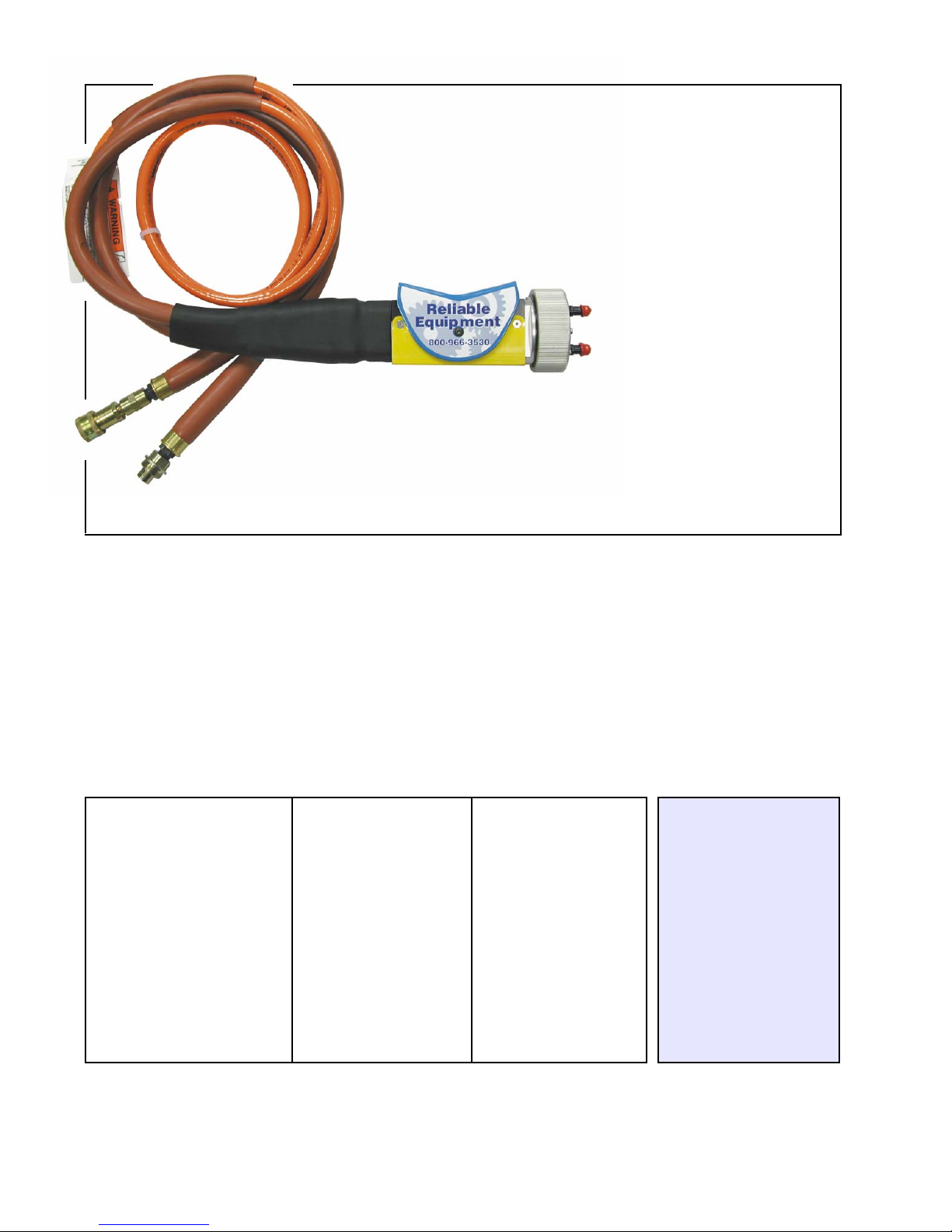
TYPICAL DOUBLE-ACTING
HIGH-PRESSURE
CUTTING OR CRIMPING SYSTEM
Shown with Double Acting
Direct Connect Control Valve
High Pressure Hose Set
Double Acting
Control Valve Double Acting
Crimping Heads
High-pressure hoses may be
used for remote operation.
Double Acting
Cable Cutters
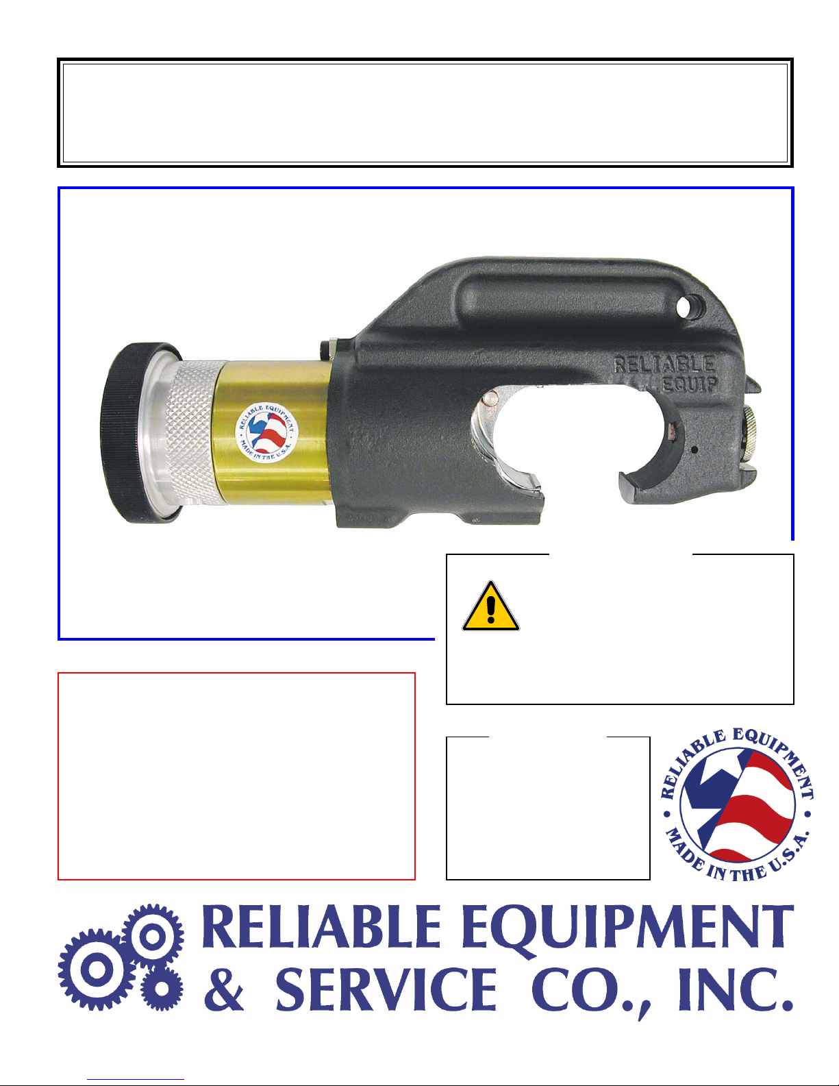
DOUBLE-ACTING TOOLS ARE BUILT TO PROVIDE SAFETY, QUALITY AND
RELIABILITY IN EVERY STEP OF HIGH PRESSURE TOOL OPERATION.
In most cases, double-acting tools are lighter and more compact than comparable crimping and cutting
equipment, insuring easier and safer use. This is especially important in compact working areas and hot
stick use when every ounce of a tool’s weight is felt by the operator.
The one-hand valve operation is safer and easier to use, leaving your other hand free to control the tool
head. Each valve has two pressure reliefs for extra safety: One to reduce the return cycle pressure to
prevent damage to the tool; The second to protect against over pressurizing.
DOUBLE-ACTING HYDRAULIC SYSTEM
Superior Performance - beats competitive
power tool systems on key features and benefits.
Better tool control - start, stop, feather, and
position your crimping or cutting head with ease.
No die hang-ups - crisply retracts the die
after every crimp.
Compatible with many existing tool and die
inventories or convert your existing tools and
dies to our double-acting system.
Consistent Pressure - Delivers up to 10,000 psi
at tool head, regardless of positioning.
Quality Features - Lightweight, built-in pressure
reliefs; ground dumps; scavenger pump reduces
back-pressure problems; one-hand valve
operation; and certified non-conductive hoses.
Portability - Lighter and more streamlined than
most other tools.
Adaptability - Use Reliable tools with your
truck’s existing system or one of our portable
power units.
VALVES
Reliable valves feature one-hand operation for
extreme ease of use. They can be direct-coupled
to the tool or, if you wish, attached with hoses for
remote operation. In addition, they feature a built-
in relief valve to limit tool return pressure and a
ground dump safety valve to prevent over
pressurizing in case the return hose becomes
disconnected or plugged.
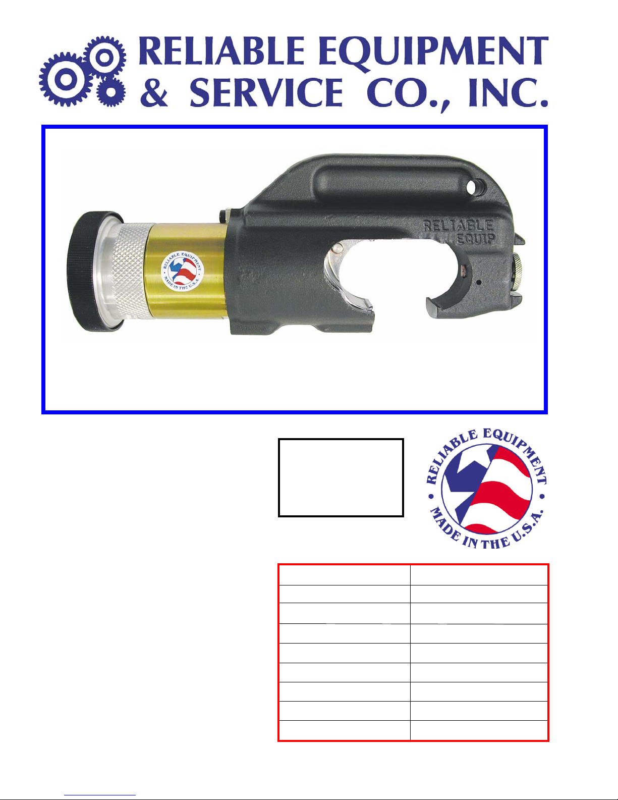
CRIMPING HEADS
In many cases, double-acting crimping heads are
significantly lighter than competitive models. Safety
is designed-in as well. One example: A pressure
reducing cavity is designed into each head to
reduce the risk of personal injury from a high-
pressure oil leak.
CUTTERS
All cutters are double-acting and available in
capacities from 1/2 in. to 4 in. Some models can
handle a wide range of materials, including rebar,
ACSR, guy strand, and bolts. Other safety features
include hoses rated at four times the working
pressure, and dielectrically safe hoses.

6
PVA-1122
DOUBLE-ACTING DIRECT CONNECT
4 WAY CONTROL VALVE
Open center 4-way, 3-position control valve used for controlling double-acting
Crimping Heads and Cutters. Connect directly to the tool or use with high pressure
hoses for remote operation. The Pivot Style Control Valve may be operated with
one hand, leaving the second hand free to control the head.
Lever “locks” in the forward position for tool advance, and in the rear position for
tool retraction. Returns automatically to center “OFF” position when rated tool
pressure is reached.
The Ground Dump Safety Valve, a standard feature, will activate if the return line is
not connected. It protects the system by dumping the flow into the atmosphere.
FEATURES:
• Compact Design
• Controlled Advance with Built-in Hold Feature
• Tool Return Circuit 5,000 psi Return Line
• 6,200 psi Return Line Ground Dump Safety Valve
Dimensions:
Length: 7 in.
Width: 2 in.
Hight: 3.5in.
Weight: 2.5 lb.
PVA 1122 is 3 lb.
W/ Coupler
SPECIFICATIONS PVA 0022 PVA 1122
System Double-Acting Double-Acting
Max. Oper. Pressure 10,000 psi 10,000 psi
Return Pressure 5,000 psi 5,000 psi
Port Size (Inlet) 1/4-18 NPTF 1/4-18 NPTF
Port Size (Tool) 1/4-18 NPSM 1/4-18 NPSM
Couplers H/P 10,000 psi Direct
Quick Connect Connect
RELIABLE DIRECT CONNECT HEADS
HAVE BEEN DESIGNED FOR USE WITH
NOTE: Any of the RELIABLE direct connect tool heads may also be used with
the PVA 0022 or comparable 4 way control valve with the addition of a set of
high pressure couplers.

7
WARNING
BEFORE USING THIS TOOL, READ THE WARNINGS
and the recommended practices described in this manual.
Failure by the operator to read and fully understand these
warnings will leave this person unqualified to use and
operate this tool. Property damage, severe personal injury,
and/or death could result by not following these warnings.
Eye
Protection
These warnings will appear in appropriate locations when they are pertinent to the
particular subject being shown. Read each one carefully and follow them strictly.
WARNING
Always wear eye protection to avoid
injury from flying debris or hydraulic
oil leaks. Failure to do so can result
in serious personal injury.
Hard Hat
WARNING
Always wear a hard hat to avoid injury
from falling debris. Failure to do so
can result in serious personal injury.
Hearing
Protection
WARNING
Always wear hearing protection, to
avoid hearing loss due to long term
exposure to high noise levels.
Foot
Protection
WARNING
Always wear foot protection.
Failure to do so can result in serious
personal injury.
Skin
Irritation
WARNING
WARNING
Protective
Gloves
Always wear protective gloves
Failure to do so can result in serious
personal injury.
Hydraulic oil may cause irritation.
Use care to prevent contact with skin.
In case of accidental contact, wash
affected area immediately

8
WARNING
HYDRAULIC POWER SUPPLY
DO NOT attempt to make any changes to any of the component
parts or accessories when connected to the power source.
DO NOT adjust, inspect, or clean tool while the tool is connected
to the power source. The tool could accidentally start up
and cause serious injury.
DO NOT lock the tool in the On Position. In an emergency,
serious damage or injury could occur during the time
required to stop the tool.
SAFE OPERATION & CARE
USE THIS TOOL FOR ITS INTENDED PURPOSE ONLY
Any other use can result in injury or property damage.
INSPECT TOOL BEFORE USE. Replace any worn, damaged or
missing parts. A damaged or improperly assembled tool may
malfunction, injuring operator and/or nearby personnel.
INSPECT HYDRAULIC HOSES AND COUPLINGS before
each use. Repair or replace if any cracking, leakage, wear or
damage is found. Worn or damaged hoses may fail resulting
in personal injury or property damage.
CLEAR WORK AREA of all bystanders and unnecessary
personnel before operating this tool.
KEEP ALL PARTS OF THE BODY AWAY FROM MOVING PARTS.
Failure to observe this warning could result in serious injury.
WARNING
OIL INJECTION INJURY
Hydraulic oil or fluid under the skin is a serious injury. Oil
under pressure can penetrate the skin and may cause
dismemberment or loss of life. Seek medical assistance
immediately if such an injury should occur.
Always wear safety gloves, eye protection and all required
safety equipment when operating or handling this tool.
DO NOT use fingers or hands to attempt to locate a leak.
DO NOT handle hoses or couplers while system is pressurized.
NEVER open or service the system before depressurizing.
WARNING

9
HOSES AND FITTINGS
There exists the potential for shock in using anything other
than certified nonconductive hoses and hydraulic oil with
dielectric properties, when using system components near
energized electrical lines. Failure to recognize these conditions
could cause electrocution.
Hoses and fittings used with this tool must comply with S.A.E. J1273 which covers
recommended practice for selection, installation, and maintenance of hose and hose
assemblies. The correct hoses and fittings are available from your supplier.
WARNING: Failure to comply with these warnings could result in severe bodily injury.
WARNING
UNIT/HOSE CONNECTIONS
ALWAYS DISCONNECT pump/power source and move toggle
switch to OFF before connecting or disconnecting any components.
ALWAYS DEPRESSURIZE hydraulic system, before slowly
disconnecting this unit or any of the systems components.
ALWAYS TIGHTEN couplings completely. Loose or improperly
tightened couplings will not allow fluid to pass through the
hose creating a blockage in the supply or return line.
ALWAYS INSPECT HOSES AND CONNECTORS before
connection to tool. Replace or repair if any leakage is evident.
Leakage is a sign of deterioration in component parts. Worn or
leaking parts must be repaired or replaced, or tool damage or
severe injury could result.
WARNING
HOSE INSTALLATION
ALWAYS ENSURE CONNECTORS ARE CLEAN
DOUBLE ACTING - Care must be taken to assure the correct
connection of the hoses to the pressure and return (tank) ports.
Connect the return hose to the return (tank) port on the power
source, then to the return port on the tool.
Connect the pressure hose to the pressure port on the tool, then
to the “P” pressure port on the power source.
Operation with hydraulic flow reversed can cause malfunction.
Failure to fully comply can result in severe injury or death.
CAUTION

10
GENERAL SAFETYGENERAL SAFETY
GENERAL SAFETY
USE ALL APPROPRIATE AND APPLICABLE PERSONAL SAFETY EQUIPMENT as required
by the operating company.
ALWAYS INSPECT TOOL for wear or deterioration every day. Replace all parts that
show signs of wear or damage.
KEEP ALL PARTS OF THE BODY AWAY from moving parts of the tool.
KEEP HANDS OUT FROM BETWEEN FIXED AND MOVING JAWS AT TOOL HEAD.
HANDS SHOULD BE OUTSIDE DANGER ZONE PRIOR TO ACTIVATING JAWS.
MAKE SURE there is no person in close proximity to you or the tool who could be
injured by any operation being performed, tool malfunction or flying debris.
DO NOT OVEREXTEND your position by overreaching or unbalancing the footing
necessary to maintain physical control of your body.
ALWAYS MAINTAIN a firm grip on the tool to avoid loss of control during an operation,
causing property damage, serious injury or death.
USE THIS TOOL FOR THE MANUFACTURERS’ INTENDED PURPOSE ONLY.
OBSERVE CLOSELY ALL SAFETY RULES FOR A PARTICULAR JOB CLASS
FAILURE TO HEED THESE WARNINGS COULD RESULT IN
PROPERTY DAMAGE, SERIOUS PERSONAL INJURY OR DEATH.
ELECTRICAL SHOCK HAZARD
Always wear and use the necessary clothing, equipment and
safety practices to protect against electrical shock. Failure to
follow these rules can result in serious personal injury or death.
WARNING
WARNING
Operation/Safety methods may vary in accordance
with the working guidelines established by each utility
or contractor.
For your own safety, ensure that you fully comply with
all safe operation guidelines required by your employer.

11
SERIOUS BURN HAZARD
HOT SURFACES MAY CAUSE SERIOUS BURNS.
The hydraulic cylinder may be hot during and after operation.
CACA
CACA
CAUTION:UTION:
UTION:UTION:
UTION: HYDRAULIC FLUID MAY CAUSE SERIOUS BURNS.
Never disconnect tool, hoses, or fittings while the hydraulic
power source is running or if the hydraulic fluid is hot.
Failure to observe this warning could result in serious injury.
WARNING
WARNING
CRIMP DANGER
This hydraulic crimping tool can crush and/or disable.
KEEP ALL PARTS OF THE BODY AWAY FROM MOVING PARTS.
DO NOT lock the tool in the On Position. In an emergency,
serious damage or injury could occur during the time required
to stop the tool.
Failure to observe this warning could result in serious injury
.
TOOL HAZARD
DO NOT OPERATE TOOL WITHOUT DIES.
DO NOT EXCEED THE MAXIMUM HYDRAULIC FLOW, RELIEF
PRESSURE, OR BACK PRESSURE.
Failure to observe warnings could result in tool damage or injury.
WARNING
WARNINGWARNING
WARNINGWARNING
WARNING
FIRE HAZARDFIRE HAZARD
FIRE HAZARD
An incomplete crimp may pose a fire hazard.
Always use the appropriate connector, die set, and
compression tool, as required by the intended application.
Compression tool should be tested on a regular schedule to
ensure acurate compression.
Failure to observe this warning could result in serious injury.
IF YOU HAVE ANY QUESTIONS REGARDING THE SAFE USE
AND/OR OPERATION OF THIS TOOL, CONSULT YOUR AREA SUPERVISOR,
OR CONTACT RELIABLE EQUIPMENT AT 800-966-3530

12
Read entire manual prior to using this tool.
(Refer to all safety recommendations and warnings)
Observe all safety precautions and procedures required by the operating company.
(Also refer to SAFETY information found on pages 5 through 9)
Before crimping, ensure that crimp is within the capacity listed for the tool.
Refer to connector manufacturer’s instructions for cable preparation and crimping procedure.
Ensure that you are using the proper die, as recommended by the connector manufacturer.
WARNING: DO NOT OPERATE TOOL WITHOUT DIES
1. Ensure that proper 10,000 psi power source is turned OFF and valve is in OFF position.
2. Connect to a 10,000 PSI power source with an audible “Pop Off” type relief valve.
(Recommended) (Refer to page 7 UNIT/HOSE CONNECTION)
3. Ensure that the ram is fully retracted.
4.Insert proper die into die seat.
OPERAOPERA
OPERAOPERA
OPERATIONTION
TIONTION
TION
5. Place tool over connector. Center connector between the dies.
6. Align jaw as necessary to ensure proper crimp. Position subject at a 90O angle to the tool.
KEEP HANDS AND ALL BODY PARTS AWAY FROM COMPRESSION OPERATION
7. Turn power source “ON” and activate control valve to advance compression dies
up to subject. Check tool alignment.
8. Continue to advance until “pop off” is felt or heard and full pressure has been obtained.
9. Use valve or double acting pump to retract dies.
10. Repeat procedure as required by compression sleeve or regulating authority.
11. Visually inspect crimp for correctness.
12. Return source to the “OFF” position and allow to retract completely.
Manufacturer recommends regular testing for proper pressure and operation.
Test at least every 6 (six) months, test more often under heavy usage.
INSERT DIE
UNDER LIP
PULL
INSERT DIE
UNDER LIP
PUSH
Pull die retainer knob and
slide die under die lip.
Press die retainer button
and slide die under lip.
Ensure both die halves are
installed and secure.

13
This tool requires well-trained experienced personnel for major repairs, adjustments or
maintenance. Complete disassembly is not recommended. Return the unit to an
authorized dealer for total disassembly and/or repair. It is suggested that tools requiring
repairs be returned to Reliable Equipment for correction unless overall local conditions are
adequate and service training has been provided. Reliable Equipment is set up to provide
quick maintenance and overhaul service. Contact your Reliable Equipment representative if
service is required.
All maintenance or disassembly should take place on a flat, clean work surface covered
with towels or wipers so as to have a clean space for the disassembled parts.
Inspect each part during disassembly for wear, scratches, and cuts. Discard the worn or
damaged parts and replace with new factory authorized parts.
O-rings are sensitive to sharp edges. Inspect closely for cuts or damage. A small cut
will cause a leak. When assembling or disassembling O-rings, use hydraulic fluid as a
lubricant to help disassembly or installation.
NOTICE: When disposing of hydraulic fluid, parts or components observe all federal,
state, and local guidelines.
IF YOU HAVE QUESTIONS REGARDING THE REPAIR AND MAINTENANCE OF THIS TOOL
CONTACT RELIABLE EQUIPMENT OR YOUR RELIABLE EQUIPMENT REPRESENTATIVE.
GENERAL MAINTENANCEGENERAL MAINTENANCE
GENERAL MAINTENANCE
DAILYMAINTENANCE
The life, reliability, and safety of the tool is dependent on proper use and maintenance.
STORE THE TOOL PROPERLY . . . Before storing tools release pressure and ensure
the ram is fully retracted. This protects the operating ram from moisture and condensation.
NOTE: When the tool has been stored for extended period of non-use, the tools should
be activated approximately every 3 weeks to keep o-rings and seals lubricated.
Clean and inspect all surfaces including tool head, ram, body and connectors.
Particularly avoid joint compounds from building up on the die retainers and ram.
WARNING: Head, retainers, and/or parts may cut or pinch. Please use extreme caution.
Worn or damaged parts may malfunction during operation, causing more extensive damage
to the tool and/or severe injury to the operator or bystander.
All parts must be replaced with new parts if signs of wear or damage are evident.
DO NOT MAKE ADJUSTMENTS TO THE TOOL . . . There are no adjustments on
this tool which can be made in the field. If a tool becomes inoperative and the instructions
in this booklet do not correct the malfunction have the tool serviced by RELIABLE
EQUIPMENT or an authorized service provider.
Keep Label Set clean and legible. Replace decals when necessary.

14
PDY-510 PARTS LIST
# PART QTY PART #
1 RAM ............................................................................................ 1 R19001K
2 OUTTER CYLINDER ................................................................... 1 R19002
3 CYLINDER .................................................................................. 1 R19003
4 C-FRAME .................................................................................... 1 R19100
5 PISTON RETAINER .................................................................... 1 R19005
6 BALL ........................................................................................... 1 R19006
7 FLAT POINT SCREW ................................................................. 1 R19007
8 INNER PISTON ........................................................................... 1 R19008
9 WIPER ........................................................................................ 1 *
10 DIE BUTTON ............................................................................... 1 R13810
11 DIE RETAINER ............................................................................ 1 R13811
12 COMPRESSION SPRING .......................................................... 1 R19012
13 SPRING PIN ................................................................................ 1 R19013
14 RETAINING RING ........................................................................ 1 R19014
15 BACK UP RING .......................................................................... 4 *
16 BACK UP RING .......................................................................... 1 *
17 O-RING ........................................................................................ 1 *
18 BACK UP RING .......................................................................... 1 *
19 KEY ............................................................................................. 1 R19019
20 SCREW ....................................................................................... 1 1220-7
21 LOCK WASHER ......................................................................... 1 1220-15
22 SCREW ....................................................................................... 1 1220-9
23 CYLINDER ROTATIONAL LOCK ................................................. 1 1220-18
25 O-RING ........................................................................................ 1 *
26 BACK UP RING .......................................................................... 1 *
27 O-RING ........................................................................................ 2 *
29 O-RING ........................................................................................ 1 *
31 O-RING ........................................................................................ 1 *
32 BACK UP RING .......................................................................... 1 *
34 O-RING ........................................................................................ 1 *
35 BACK UP RING .......................................................................... 1 *
36 END CAP .................................................................................... 1 R19058
37 O-RING ........................................................................................ 2 *
38 O-RING ........................................................................................ 3 *
39 PIPE PLUG ................................................................................. 2 R19039
40 CHECK BALL .............................................................................. 1 R19040
41 PINTLE ........................................................................................ 1 R19041
42 COMPRESSION SPRING .......................................................... 1 R19042
43 SET SCREW .............................................................................. 1 R19043
44 FLAT WASHER ........................................................................... 4 1220-10
45 SCREW ....................................................................................... 4 1220-12
46 LOCK WASHER ......................................................................... 4 1220-11
47 NUT ............................................................................................. 1 1220-8
48 LOCK WASHER ......................................................................... 1 1220-14
49 FLAT WASHER ........................................................................... 11220-13
50 DIPPED BUTTON ........................................................................ 1 1220-20D
51 SCREW ....................................................................................... 1 1220-3
52 SPRING ....................................................................................... 1 1220-4
53 RETAINER PIN ............................................................................ 1 1220-5
54 DRIVE PIN .................................................................................. 1 1220-16
55 CAP PLUG .................................................................................. 2
56 THREAD PROTECTOR ............................................................... 1 1220-19
57 ROLL PIN .................................................................................... 1 1220-17
* SEAL KIT(*ITEMS INCLUDED IN KIT) ......................................... R19050

15
PDY-510 PARTS DRAWINGS

16
Date Parts or Service Required
Maintenance Records
301 Ivyland Road Warminster, PA 18974
Phone: 800-966-3530 Fax: 215-357-9193
Visit us on the web at www.Reliable-Equip.com
If you have any questions regarding the information
found in this manual please contact RELIABLE EQUIPMENT at the
address, phone or fax numbers shown below.
BEFORE USING THIS PRODUCT
READ THE SAFETY WARNINGS
and recommended practices described
in the manual. Failure by the operator to
read and fully understand the warnings
will leave this person unqualified to use
and operate the tool.
Failure to observe all warnings and instructions could result
in property damage, severe personal injury, and/or death.
ELECTROCUTION
HAZARD
The user should be properly
trained in the correct procedures
required for work on or around
electrical lines.
REL-SM
WARNING
NOTE: Keep Label Set clean
and legible. Replace decals
when necessary.
Table of contents
Other Reliable Equipment Power Tools manuals
Popular Power Tools manuals by other brands

BGS technic
BGS technic 2834 instruction manual

STERWINS
STERWINS 8VGS2-3IN1.1 Assemby - Use - Maintenance Manual

Chicago Electric
Chicago Electric 66098 Set up and operating instructions

OK International
OK International MX-DS1 user guide

Titan
Titan CAPSpray 0524000 owner's manual

REMS
REMS MSG 25 EE Translation of the original instruction manual