Model F1FR Quick Response Concealed Pendent Sprinklers
Installation Wrench: Model RC1 Sprinkler Wrench
Technical Data:
Nominal
Orifice
“K” Factor Thread
Size Model
Temp. Rating Max.
Ambient
Temp
Bulb
Color Approvals
Sprinkler
Identification
Number(SIN)
US Metric Sprinkler Cover
½” (15mm) 5.6 80 ½” NPT F1FR 135°F/57°C 135°F/57°C 100°F/38°C Orange 1, 2 RA1414
½” (15mm) 5.6 80 ½” NPT F1FR 155°F/68°C 135°F/57°C 100°F/38°C Red 1, 2, 4(1) RA1414
½” (15mm) 5.6 80 ½” NPT F1FR 175°F/79°C 165°F/74°C 100°F/38°C Yellow 1, 2 RA1414
½” (15mm) 5.6 80 ½” NPT F1FR 200°F/93°C 165°F/74°C 100°F/38°C Green 1, 2 RA1414
(1) For VdS only = 155°F/68°C Norbulb and 1/2” [12,7mm] adjustment.
Figure 1 Figure 2
Installation Aid
A protective cap is included for use during installation.
Important: The F1FR 56 Sprinkler with Model CCP cover
plate is not an FM Approved combination.
Installation
Quick response sprinklers are intended for installation
as specified in NFPA 13. Quick response sprinklers and
standard response sprinklers should not be intermixed.
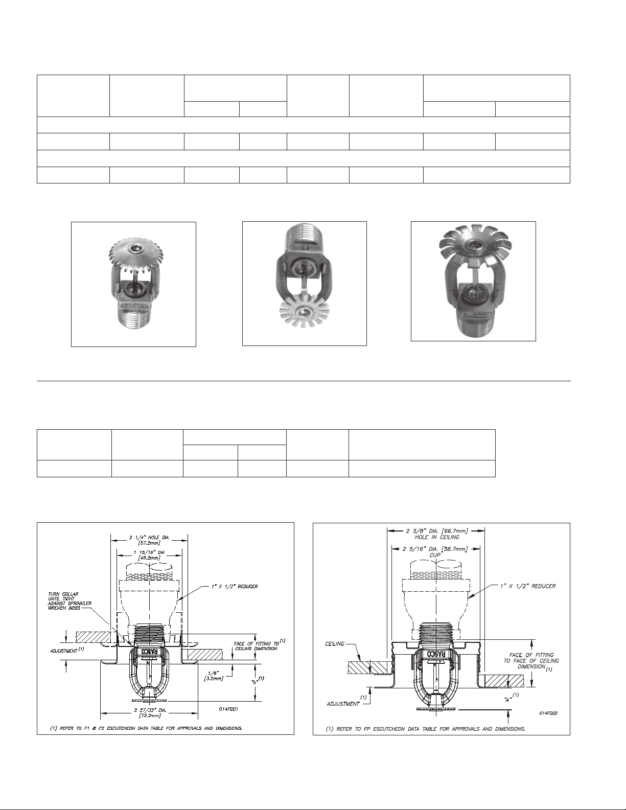
The Model F1FR 56 Recessed Quick Response Sprin-
klers are to be installed as shown. The Model F1 or F2 Es-
cutcheons illustrated are the only recessed escutcheons
to be used with the Model F1FR 56 Sprinklers. The use
of any other recessed escutcheon will void all approvals
and negate all warranties.
When installing Model F1FR 56 Sprinklers, use the
Model D Sprinkler Wrench. Use the Model GFR2 Wrench
for installing F1FR 56 Recessed Pendent Sprinklers. Any
other type of wrench may damage these sprinklers.
NOTE: A leak tight ½” NPT (R1/2) sprinkler joint can
be obtained with a torque of 8-18 ft-lbs (10,8 - 24,4 N-m).
Do not tighten sprinklers over maximum recommended
torque. It may cause leakage or impairment of the sprin-
klers.
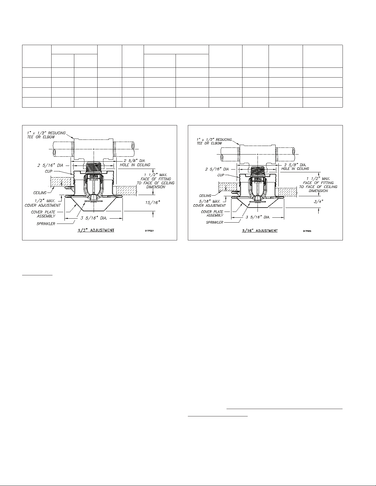
The Model F1FR 56/ CCP Concealed Sprinkler uses the
½” orifice, ½” NPT (R1/2), 135°F (57°C), 155°F (68°C),
175°F (79°C) or 200°F (93°C) Model F1FR 56 Pendent
Sprinkler with a threaded Model CCP cup which is fac-
tory attached to the sprinkler. The assembly is complet-
ed by the installation of the attractive, low profile, 135°F
(57°C) or 165°F (74°C) rated Model CCP push on cover
plate assembly. The cover plate and sprinkler cup as-
semblies are joined using a cover plate skirt with flexible
tabs for threaded engagement. A choice of two cover
plate assemblies provide either ½” (13mm) or 5/16” (8mm)
of cover adjustment.
Do not install these sprinklers in ceiling which have
positive pressure in the space above.
After a 25/8” (67mm) diameter hole is cut in the ceil-
ing, the sprinkler is easily installed with the Model RC1
Wrench. A Teflon* based thread sealant should be
applied to the sprinkler threads only. The Model RC1
Wrench is then used to engage the sprinkler wrenching
surfaces and to install the sprinkler in the fitting. When
inserting or removing the wrench from the sprinkler/cup
assembly, care should be taken to prevent damage to
the sprinkler. DO NOT WRENCH ON ANY OTHER PART
OF THE SPRINKLER. The cover plate is then pushed
onto the cup. Final adjustment is made by hand turning
the cover plate until the skirt flange makes full contact
with the ceiling. Cover plate removal requires turning in
the counter clockwise direction.
4.