Reliance Skyloc 4 Series User manual

INSTRUCTIONS FOR USE
4XXX - 4XXXXXX Series Skyloc™/
Skyloc II™/Roto-Loc™/Enviro-Shield™
Self Retracting Lifelines
Phone : 281-930-8000
Toll Free : 888-362-2826
Fax : 281-930-8666
Complies with the current ANSI Z359.14 and
all applicable OSHA regulations and requirements.
Reliance Industries
P.O. Box 2046
Deer Park, TX 77536

Page 2
Contents
DESCRIPTION 3 - 8
PRODUCT SPECIFICATIONS 9 - 10
APPLICATION 9
A. PURPOSE ....................................................................................................................9
1) PERSONAL FALL ARREST..................................................................................9
B. USE LIMITATIONS .......................................................................................................9
1) CAPACITY ...........................................................................................................9
2) FREE FALL ........................................................................................................10
3) FALL CLEARANCE .....................................................................................10 - 11
4) SWING PENDULUM FALLS ......................................................................11 - 13
5) CHEMICAL HAZARDS .......................................................................................13
6) HEAT...................................................................................................................13
7) CORROSION.............................................................................................. 13 - 14
8) ELECTRICAL HAZARDS....................................................................................14
9) MOVING MACHINERY.......................................................................................14
10) SHARP EDGES AND ABRASIVE SURFACES ..................................................14
11) WEAR AND DETERIORATION...........................................................................14
12) IMPACT FORCES...............................................................................................14
SYSTEMS REQUIREMENTS 15
A. COMPATIBILITY OF SYSTEM PARTS......................................................................15
1) COMPATIBILITY OF COMPONENTS AND SUBSYSTEMS ................................15
2) COMPATIBILITY OF CONNECTORS...................................................................15
3) ANCHORAGES AND ANCHORAGE CONNECTORS..........................................16
INSTALLATION PROCEDURE 16
A. CONNECTING THE SRL TO AN ANCHOR POINT ..................................................16
B. PREPARATION FOR USE .......................................................................................17
C. INSPECT PRIOR TO USE .........................................................................................17
D. PLAN SCOPE OF WORK TO BE PERFORMED, ANALYSIS .......................... 18 - 19
CARE OF THE SKYLOC/SKYLOC II/ENVIROSHIEL SRL 19 - 20
INSPECTIONS 20
A. INSPECTION FREQUENCY ......................................................................................20
B. INSPECTION PROCEDURE.............................................................................. 20 - 22
TRAINING 22
RESCUE PLANNING 23
SERVICING 23
GUARDING AGAINST APPLICATION FAILURE 23 - 24
WARNINGS AND LIMITATIONS 24 - 25
LABELING 25 - 28
INSPECTION RECORD 30
PART NUMBER LIST 31
WARRANTY STATEMENT 31

Instructions for Use
Page 3
User Instructions
Reliance Self Retracting Lifelines
User Instruction Manual - Self Retracting Lifelines
This manual is intended to meet the Manufacturer’s Instructions as required by
the current ANSI Z359.14, and should used as part of an employee training pro-
gram as required by OSHA.
WARNING: This product is one part of a personal fall arrest, restraint, work posi-
tioning, personnel riding, climbing, or rescue system. Without the other necessary
components in such sub-systems the self retracting lifeline itself serves no useful
purpose. The user must follow the manufacturer’s instructions for each compo-
nent of the system. These instructions must be provided to the user before using
this product and retained for ready reference by the user. The user must read,
understand (or have explained), and heed all instructions, labels, markings and
warnings supplied with this product and with those products intended for use in
association with it before using this equipment. Manufacturer’s instructions must
be followed for proper use and maintenance of this equipment. National stan-
dards and state, provincial and federal laws require the user to be trained before
using this product. This manual can be used as part of a such a user safety-
training program that is appropriate for the user’s occupation.
IMPORTANT: Alterations or misuse of this product or failure to follow in-
structions may result in serious injury or death. If you have questions on the
use, care, or suitability of this equipment for your application, contact RELIANCE
Fall Protection for information.

Page 4
Identifying Components of Skyloc™/Skyoc II™/Roto-Loc™/
EnviroShield™Self Retracting Lifelines
Figure 1
4102050-1, 4102130-1
DESCRIPTION
The Skyloc™/Skyloc II™/Roto-Loc™/Enviro-Shield™Self Retracting Lifeline (SRL)
is designed to be a component in a personal fall arrest systems (PFAS). It may be
used in most situations where a combination of worker mobility and fall protection
is required (i.e. inspection work, general construction, maintenance work, oil
production, conned space work, etc.). The Skyloc™/Skyloc II™/Roto-Loc™/Enviro-
Shield™SRL is designed for use by a single person weighing up to 400 lbs [181kg]
(body weight plus tools) *PLEASE NOTE - capacity is specic to lifeline model.
See Page 7 for complete details. Skyloc™/Skyloc II™/Roto-Loc™/Enviro-Shield™
Self Retracting Lifeline features a cam-action pawl system ensuring positive lock-
up even in the most demanding environments. Available standard cable / web
lengths allow the Skyloc™/Skyloc II™/Roto-Loc™/Enviro-Shield™to be mounted
overhead in areas where there are no other convenient anchor points for personal
fall arrest means. The Pelican™snap-hook’s unique hook body design prevents
the accidental “false engagement” to the harness dorsal D-ring, while the case
swivel or anchor connector (depending on model) provides an easy to see load
indicator showing whether the Skyloc™/Skyloc II™/Roto-Loc™/Enviro-Shield™has
been exposed to a fall arrest load and needs to be serviced.
Anchor Connector
Slot
Housing
Front Label
Load Indicating
Swivel
Carabiner
Easy Grip Cable Pull
Carry
Handle

Instructions for Use
Page 5
Easy Grip Cable Pull
Figure 2
4000020-1, 4000030-1, 4000050-1, 4000085-1, 4000100-1,
4008025-1, 4008040-1, 4008080-1
Swiveling
Anchor Connector
Housing
Carry Handle
Front Label
Carry
Handle
Load Indicating
Swivel
Snap Hook
Figure 3
4302020-1, 4302030-1, 4302050-1, 4302080-1, 4302100-1
Swiveling
Anchor Connector
Housing
Carry Handle
Load Indicating
Swivel
Carabiner
Carry
Handle
Front Label
Easy Grip Cable Pull

Page 6
Figure 5
4015, 4020
4030, 4050, 4051, 4075, 4100, 4101, 4120, 4121, 4130, 4131
Web or Cable lanyard
Rubber Overmold
Load Indicating
Anchor Connector
Housing
Label Area
Snap Hook
Load Indicating
Swivel
Snap Hook
Label
Rear Cover
Acorn Nut
Figure 4
Handle
Handle Screw
& Nut (2X)
Housing Screws
& Nuts (12X)
Torque Nut
Cover
Serial Number
Label Area
Nozzle
3/16” (4.5mm)
Wire Rope
Washer
Rubber Ball Stop
Ferrules (2X)
Thimble Eye
Thimble Eye
Ferrules (2X)
Rubber Ball Stop

Instructions for Use
Page 7
Figure 6
4400012-1
Easy Grip Cable Pull
Load Indicating
Swivel
Housing
Label Area
Snap Hook
Housing
Load Indicating
Anchor Swivel

Page 8
PRODUCT SPECIFICATIONS
Part # Working
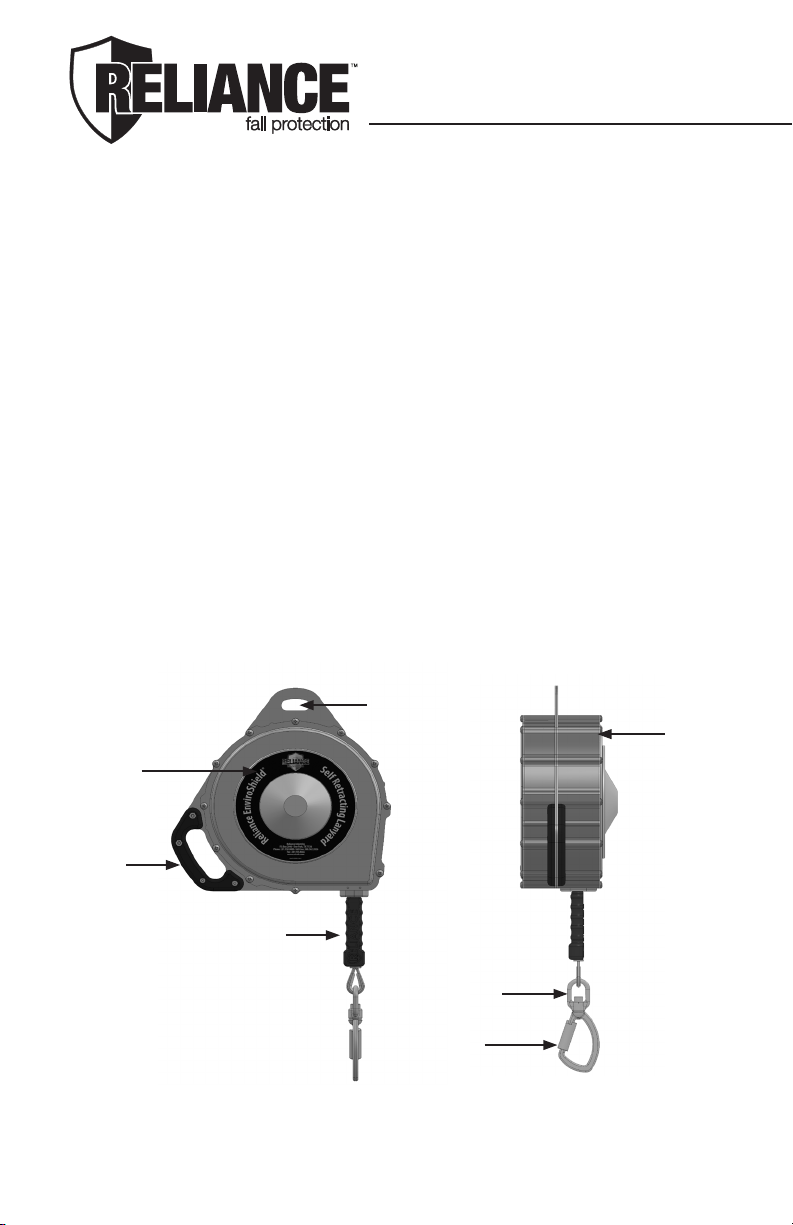
Length Line Type Weight Capacity Hook Type Housing
Type
Housing
Dimensions
4015 18’ (5.5m) 3/16” (4.5mm)
galvanized 7 lbs (3.1kg) 400 lbs (181kg) 3006 Pelican
Zn Plate
LDPE over ABS
Plastic
11”L X 6”W X 3”H
(28cm X 15cm X 8cm)
4020 20’ (6.1m) 1” (25mm)
polyester web 8 lbs (3.6kg) 400 lbs (181kg) 3006 Pelican
Zn Plate
LDPE over ABS
Plastic
11”L X 6”W X 3”H
(28cm X 15cm X 8cm)
4030 30’ (9.1m) 3/16” (4.5mm)
galvanized 25 lbs (11.3kg) 400 lbs (181kg) 3007 Swivel
Zn Plate Carbon Steel 15”L X 9”W X 4”H
(38cm X 23cm X 10cm)
4031 30’ (9.1m) 3/16” (4.5mm)stainless 25 lbs
(11.3kg) 400 lbs (181kg) 3008 Swivel
Stainless Stainless Steel 15”L X 9”W X 4”H
(38cm X 23cm X 10cm)
4050 50’ (15.2m) 3/16” (4.5mm)
galvanized
26 lbs
(11.7kg) 400 lbs (181kg) 3007 Swivel
Zn Plate Carbon Steel 15”L X 9”W X 4”H
(38cm X 23cm X 10cm)
4051 50’ (15.2m) 3/16” (4.5mm)stainless 26 lbs
(11.7kg) 400 lbs (181kg) 3008 Swivel
Stainless
Stainless
Steel
15”L X 9”W X 4”H
(38cm X 23cm X 10cm)
4075 75’ (22.8m) 3/16” (4.5mm)
galvanized
48 lbs
(21.7kg) 400 lbs (181kg) 3007 Swivel
Zn Plate Carbon Steel 19”L X 13.5”W X 4.5”H
(48cm X 34cm X 11cm)
4100 100’ (30.4m) 3/16” (4.5mm)
galvanized
44 lbs
(20kg) 400 lbs (181kg) 3007 Swivel
Zn Plate Carbon Steel 19”L X 13.5”W X 4.5”H
(48cm X 34cm X 11cm)
4101 100’ (30.4m) 3/16” (4.5mm)stainless 44 lbs
(20kg) 400 lbs (181kg) 3008 Swivel
Stainless
Stainless
Steel
19”L X 13.5”W X 4.5”H
(48cm X 34cm X 11cm)
4130 130’ (39.6m) 3/16” (4.5mm)
galvanized
48 lbs
(21.7kg) 400 lbs (181kg) 3007 Swivel
Zn Plate Carbon Steel 19”L X 13.5”W X 4.5”H
(48cm X 34cm X 11cm)
4131 130’ (39.6m) 3/16” (4.5mm)stainless 48 lbs
(21.7kg) 400 lbs (181kg) 3008 Swivel
Stainless
Stainless
Steel
19”L X 13.5”W X 4.5”H
(48cm X 34cm X 11cm)
4000020-1 20' (6m) 3/16" (4.5mm)
galvanized
15 lbs
(6.8kg) 310 lbs (140kg) 3007 Swivel Zn Plate Fiberglass-
Reinforced Nylon
11"L X 12"W X 4" H
(28cm X 30 cm x 10 cm)
4000030-1 30' (9.1m) 3/16" (4.5mm)
galvanized
17 lbs
(7.7kg) 310 lbs (140kg) 3007 Swivel Zn Plate Fiberglass-
Reinforced Nylon
11"L X 12"W X 4" H
(28cm X 30 cm x 10 cm)
4000050-1 50' (15.2m) 3/16" (4.5mm)
galvanized
22 lbs
(10.0kg) 310 lbs (140kg) 3007 Swivel Zn Plate Fiberglass-
Reinforced Nylon
12"L X 13"W X 4" H
(30cm X 33 cm X 10 cm)
4000085-1 85' (25.9m) 3/16" (4.5mm)
galvanized
35 lbs
(15.9kg) 310 lbs (140kg) 3007 Swivel Zn Plate Fiberglass-
Reinforced Nylon
14"L X 15"W X 4" H
(35 cm X 38 cm X 10 cm)
4000100-1 100' (30.5m) 3/16" (4.5mm)
galvanized
37 lbs
(16.8kg) 310 lbs (140kg) 3007 Swivel Zn Plate Fiberglass-
Reinforced Nylon
14"L X 15"W X 4" H
(35 cm X 38 cm X 10 cm)
4008025-1 25’ (7.6m) 1/4” (6.4mm) Dyneema
Rope
17 lbs
(7.7kg) 310 lbs (140kg) 3007 Swivel Zn Plate Fiberglass-
Reinforced Nylon
11”L X 12”W X 4” H
(28cm X 30 cm x 10 cm)
4008040-1 40’ (12.2m) 1/4” (6.4mm) Dyneema
Rope
19 lbs
(8.6kg) 310 lbs (140kg) 3007 Swivel Zn Plate Fiberglass-
Reinforced Nylon
12”L X 13”W X 4” H
(30cm X 33 cm X 10 cm)
4008080-1 80’ (24.4m) 1/4” (6.4mm) Dyneema
Rope
32 lbs
(14.5kg) 310 lbs (140kg) 3007 Swivel Zn Plate Fiberglass-
Reinforced Nylon
14”L X 15”W X 4” H
(35 cm X 38 cm X 10 cm)
4102050-1 50’ (15.2m) 3/16” (4.5mm)stainless 41.2 lbs
(18.7kg) 310 lbs (140kg) Swivel Carabiner
Stainless
Stainless Anodized
Aluminum
12.5”L X 12.5”W X 6.5” H
(32 cm X 32 cm X 17 cm)
4102130-1 130’ (39.6m) 3/16” (4.5mm)stainless 65 lbs
(29.5kg) 310 lbs (140kg) Swivel Carabiner
Stainless
Stainless Anodized
Aluminum
14.5”L X 14”W X 7” H
(37 cm X 36 cm X 18 cm)
4302020-1 20' (6m) 3/16" (4.5mm) stainless 15 lbs
(6.8kg) 310 lbs (140kg) Swivel Carabiner
Stainless
Fiberglass-
Reinforced Nylon
11"L X 12"W X 4" H
(28cm X 30 cm x 10 cm)
4302030-1 30' (9.1m) 3/16" (4.5mm) stainless 17 lbs
(7.7kg) 310 lbs (140kg) Swivel Carabiner
Stainless
Fiberglass-
Reinforced Nylon
11"L X 12"W X 4" H
(28cm X 30 cm x 10 cm)
4302050-1 50' (15.2m) 3/16" (4.5mm) stainless 22 lbs
(10.0kg) 310 lbs (140kg) Swivel Carabiner
Stainless
Fiberglass-
Reinforced Nylon
12"L X 13"W X 4" H
(30cm X 33 cm X 10 cm)
4302080-1 80' (24.4m) 3/16" (4.5mm) stainless 35 lbs
(15.9kg) 310 lbs (140kg) Swivel Carabiner
Stainless
Fiberglass-
Reinforced Nylon
14"L X 15"W X 4" H
(35 cm X 38 cm X 10 cm)
4302100-1 100' (30.5m) 3/16" (4.5mm) stainless 37 lbs
(16.8kg) 310 lbs (140kg) Swivel Carabiner
Stainless
Fiberglass-
Reinforced Nylon
14"L X 15"W X 4" H
(35 cm X 38 cm X 10 cm)
4400012-1 12' (3.6m) 3/16" (4.5mm) stainless 5.8 lbs
(2.6kg) 310 lbs (140kg) Pelican Swivel
Zinc Plate
Sanoprene Over
ABS
8"L X 5"W X 3.5" H
(20.3 cm X 12.7 cm X 88.9 cm)

Instructions for Use
Page 9
SELF RETRACTING LIFELINE APPLICATION
A. PURPOSE:
RELIANCE Self Retracting Lifelines (SRL’s) are used as one component in a
personal fall arrest system (PFAS). The SRL’s described in this manual meet,
ANSI Z359.14 and OSHA requirements (except where noted). These instruc-
tions, and markings borne by the SRL’s, fulll the instruction and marking re-
quirements of those standards and regulations. This equipment is specically
designed to dissipate fall energy and limit the fall arrest forces that are trans-
ferred to the body.
1) PERSONAL FALL ARREST:
The self retracting lifeline is used as a component of a personal fall
arrest system. Personal fall arrest systems typically include a full body
harness, a connecting subsystem (energy absorbing device such as
a shock absorbing lanyard or self retracting lifeline) and an anchorage
connector. Average arresting force must not exceed 900 lbs (4kN) for
ANSI Z359.14, Class A and 1350 lbs (6kN) for ANSI Z359.14, Class
B. Maximum arresting force must not exceed 1,800 lbs (8kN) for ANSI
Z359.14 and OSHA.
B. USE LIMITATIONS:
Consider the following application limitations before using this equipment:
1) CAPACITY:
These SRL’s are designed for use by persons with a combined weight
(clothing, tools, etc.) of no more than 400 lbs (181kg) *Capacities vary -
please see Page 7 for full details.
PRODUCT SPECIFICATIONS (continued)
The following specications apply to all Skyloc™ and Enviro-Shield™ Self Retracting Life-
lines and meet the Class B requirements of ANSI Z359.14:
• Maximum Arrest Force (MAF): ≤ 1,800 lbs (8kN) • Average Arrest Force (AAF): ≤
900 lbs (4kN)
•Arrest Distance (AD): ≤ 42” (1.07m)
The Maximum Capacity specication is specic to the model. Please refer to the table
above for specic lifeline capacity.
• 310 lb Max. Capacity : 1 worker, max. combined tool & body weight ≤ 310 lbs (140.6kg).
• 400 lb Maximum Capacity : 1 worker, max. combined tool & body weight of ≤ 400 lbs
(181kg). Certain Models have capacity up to 440 lbs (200kg). Contact Reliance Industries if
higher capacity models are needed.
The following specications apply to all Skyloc™ II and Roto-Loc™ Self Retracting Lifelines
and meet the Class A requirements of ANSI Z359.14:
• Maximum Arrest Force (MAF): ≤ 1,800 lbs (8kN) • Average Arrest Force (AF): ≤
1,350 lbs (4kN)
•Arrest Distance (AD): ≤ 24” (0.61m)
• 310 lb Max. Capacity : 1 worker, max. combined tool & body weight ≤ 310 lbs (140.6kg).

Page 10
CALCULATE THE FALL CLEARANCE!
1) Determine distance beneath walking/working surface to nearest lower level
or obstruction : Minimum Required Clearance - MRC
2) Add the Activation Distance - Distance required for lifeline to activate -
Activation Distance - AD = 12” (.3m)
3) Add the Deceleration Distance - DD. No more than 30” (.76m)
4) Add the Safety Factor: Safety Factor - SF. 1.5’ to 3’ (.4 to .9m)
AD + DD + SF < or = MRC
Persons with muscular, skeletal, or other physical disorders should
consult a physician before using. Pregnant women and minors must
never use this equipment. Increasing age and diminished physical
tness may reduce a person’s ability to withstand shock loads during
fall arrest or prolonged suspension. Consult a physician if there is any
question about a users physical ability to safely use this product to arrest
a fall or remain suspended.
2) FREE FALL:
Personal fall arrest systems used with this equipment should be
mounted overhead in such a way as to eliminate the possibility of a free
fall. Avoid working above the anchorage level to avoid an increased free
fall distance. Avoid working where your line may cross or tangle with that
of other workers or objects.
Do not allow the lifeline to pass under arms or between legs. Never
clamp, knot, or prevent the lifeline from retracting or being taut. Avoid
slack line. Do not lengthen the SRL by connecting a lanyard or other
components without consulting Reliance.
3) FALL CLEARANCE:
There must be sufcient clearance below the user to arrest a fall before
the user strikes the ground or other obstruction. The clearance required
is dependent on the following factors (see Figure 6 for reference):
• Elevation of anchorage
• Connecting subsystem length
• Deceleration distance
• Free fall distance
• Worker height
• Movement of harness attachment element
WARNING!
WARNING!

Instructions for Use
Page 11
4) SWING PENDULUM FALLS:
Swing falls occur when the anchorage point is not DIRECTLY above
the point where a fall occurs. If the worker fall in such a situation,
there is a possibility of a swing fall that may bring him into contact
with objects below or to the side of him, possibly causing serious
injury or death. These objects must be removed or the SRL and/
or anchorage point be repositioned directly over the worker to help
reduce the risk of a swing fall. A Competent Person or Qualied
Engineer should always be consulted if there exists a possibility of a
swing fall occurring. The worker must be trained to understand that
the width of his allowable work area can never exceed the anchorage
height of the retractable over his walking/working surface.
For example, if a worker in a building with 10 ft (3m) oors walks 20 ft
(6m) away from his anchorage he could fall and strike the oor below
before his fall would extract any line from the SRL.
Figure 7

Page 12
Figure 8
RIGHT WRONG
If an object is in his swing path (or that of the line) a hazardous
situation exists. Two factors become evident in this situation :
First, due to the swing fall, horizontal speed of the worker may be
high enough to cause injury if an obstacle in the swing fall path is
struck by either the user or the line (web). The hazard increases
as the initial (before fall) length of extended cable is increased
and as the initial angle which the cable makes with the vertical
is increased. In the extreme case where a user has extended 90
ft (27.4m) of line at an angle of 30 degrees with the vertical, the
user can theoretically develop a horizontal speed of about 19mph
(30.5km/h). By comparison, if the user has extended 50 ft (15.2m) of
line at an angle of 15 degrees with the vertical, the user may develop
a horizontal speed of about 7mph (11km/h). This situation is clearly
more tolerable but it may still be dangerous if hazards such as rigid
or sharp objects, electrical conductors, or powered equipment are in
the swing fall path.
The second factor that comes into effect in a swing fall is that the
total vertical fall distance of the user may be much greater than if
the user had fallen entirely vertically without a swing fall path. This

Instructions for Use
Page 13
hazard also increases as the initial (before fall) length of extended
line is increased and as the initial angle which the line makes with the
vertical is increased. For example, if the initial extended line length
is 10 ft (3m), the drop at the bottom of the pendulum swing would
be 1.3 ft (0.4m) This is in addition to the linle extension due to the
devices internal shock absorption which may be as much as 3.3. ft
(1m). The total vertical fall distance would then be as much as 4.6 ft
(1.4m) If, however, 50 ft (15.2m) of cable is initially extended at a 30
degree angle with the vertical, then a drop at the pendulum bottom
of 6.7 ft (2m) would result. In this example, adding the 3.3 ft (1m) of
cable extension due to internal shock absorption of the device, the
total vertical fall distance could be as much as 10 ft (3m).
Minimize swing falls by working as close to the anchorage point as
possible (see Figure 8). Do not permit a swing fall if injury could
occur. Swing falls will signicantly increase the clearance required
when a self-retracting lifeline or other variable length connecting
subsystem is used.
5) CHEMICAL HAZARDS:
Acidic, alkaline, or other environments with harsh substances may
damage the webbing or synthetic rope(if equipped) and hardware
elements of this SRL. Polyester webbing is more resistant to attack
by acids, but is subject to degradation by alkaline or neutral pH
environments. If working in a chemically aggressive environment,
an SRL that uses a cable lifeline is generally recommended. When
working in the presence of chemicals, more frequent inspection of
the SRL is required.
6) HEAT:
Do not use SRL’s that utilize a web lifeline in environments with
temperatures greater than 185°F (85°C). Protect the lanyard when
used near welding, metal cutting, or other heat producing activities.
Sparks may damage the line webbing or rope and reduce its strength.
IMPORTANT: When working with tools, materials, or in high temperature
environments, ensure that associated fall protection equipment can
withstand high temperatures, or provide protection for those items.
7) CORROSION:
Do not expose the device to corrosive environments for prolonged
periods. Organic substances and salt water are particularly corrosive
to metal parts. When working in a corrosive environment more
CAUTION!

Page 14
frequent inspection, cleaning, and drying of the SRL is required. For
the most severe environments the Enviro-Shield™sealed SRL is
recommended. See Care and Inspection sections for cleaning and
inspection details.
8) ELECTRICAL HAZARDS:
Use extreme caution when working near energized electrical sources.
Metal hardware on the SRL, the lifeline itself (on cable units), and
on other components connected to it will conduct electric current.
Maintain a safe working distance [preferably at least 10’ (3m)] from
electrical hazards.
9) MOVING MACHINERY:
When working near moving machinery parts (e.g. conveyors, rotating
shafts, presses, etc.), make sure that loose equipment is secured.
Maintain a safe working distance from machinery that could entangle
clothing, the lifeline, the harness, or other components connected to
it.
10) SHARP EDGES AND ABRASIVE SURFACES:
Do not expose web lifelines to sharp edges or abrasive surfaces
that could cut, tear or abrade and weaken the bers. If working
around sharp edges and abrasive surfaces is unavoidable use
heavy padding or other protective barriers to prevent direct contact.
An energy absorbing component can sometimes be added in-line to
further protect the worker. Compatibility and total fall distance must
be considered if this is done. Contact Reliance before using an in-
line energy absorbing component or lanyard with an SRL. NOTE
on Leading Edge SRL: Although this model provides additional
protection from falls occurring over edges, protection against cutting
must be provided when working near extremely sharp edges such as
sheared, cold rolled, or ame cut steel, or rough cast edge concrete.
Edge protection is not required over edges such as hot rolled steel,
steel decking, chamfered concrete, or wood.
11) WEAR AND DETERIORATION:
Any SRL which shows signs of excessive wear, deterioration or
aging, must be removed from use and marked “UNUSABLE” until
destroyed. See detailed inspection procedures.
12) IMPACT FORCES:
Any SRL that has been subjected to the forces of arresting a fall must
be immediately removed from service and marked as “UNUSABLE”
until recertied or replaced. RELIANCE SRL’s have impact load
indicators built into either the hooks or the anchorage component on
top of the SRL that facilitate inspection for fall loading.

Instructions for Use
Page 15
SYSTEMS REQUIREMENTS
A. COMPATIBILITY OF SYSTEM PARTS
1) COMPATIBILITY OF COMPONENTS AND SUBSYSTEMS:
RELIANCE SRL’s are designed to be used with RELIANCE approved
components and connecting subsystems. Use of the SRL with products
made by others should be evaluated by a competent person to ensure
compatibility of components and hardware. Connecting subsystems must
be suitable for use in the application (e.g. fall arrest or restraint). RELIANCE
manufactures a line of connecting subsystems for most applications.
Contact RELIANCE for further information. Refer to the manufacturer’s
instructions supplied with the component or connecting subsystem to
determine suitability. Contact RELIANCE with any questions regarding
compatibility of equipment used with the SRL.
2) COMPATIBILITY OF CONNECTORS
Connectors, such as D-rings, snap hooks, and carabiners, must be
rated at 5,000 lb. (22 kN) minimum breaking strength and comply with
ANSI Z359.12-2012. RELIANCE connectors meet these requirements.
Connecting hardware must be compatible in size, shape, and strength.
Non-compatible connectors may accidentally disengage (“rollout”) or
false engage. Always verify that the connecting snap hook or carabiner
and the D-ring on the harness or anchorage connector is compatible.
Some harness models have web loop connection points. Do not use snap
hooks to connect to web loops unless the snap hook complies with ANSI
Z359.12-2012. A self-locking carabiner may also be used to connect to
a web loop. Ensure the carabiner cannot cross-gate load (load against
the gate rather than along the backbone of the carabiner). Connecting
subsystems (self retracting lifeline, lanyard, rope grab and lifeline, cable
grab, etc.) must be suitable for your application.
EXAMPLES OF INAPPROPRIATE CONNECTIONS :
A. To a D-ring to which another connector is attached
B. In a manner that would result in a load on the gate.
C. In a false engagement, where features that protrude from the snap hook
or carabiner catch on the anchor and seem to be fully engaged to the
anchor point.(Reliance has designed the width of the head and gates
of Reliance snap hooks to prevent this issue in most D-rings.)
D. To each other.
E. Directly to webbing or rope lanyard or tie-back.
F. To any object shaped such that the snap hook or carabiner will not close
and lock, or that could cause roll-out should a fall occur.

Page 16
3) ANCHORAGES AND ANCHORAGE CONNECTORS
Anchorages for personal fall arrest systems must have a strength capable
of supporting a static load, applied in directions permitted by the system,
of at least: (a) 3,600 lb. (16 kN) when certication exists, or (b) 5,000 lb.
(22.2 kN) in the absence of certication. When more than one personal
fall arrest system is attached to an anchorage, the anchorage strengths
set forth in (a) and (b) must be multiplied by the number of systems
attached to the anchorage. This requirement is consistent with OSHA
requirements under 29 CFR 1910 & 1926.
Anchorage connectors must be selected carefully. Eyebolts should not be
used if they will be loaded at an angle to their axis, unless the loads fall
within design parameters for such use. Weld-on lugs should not be less
than 1/2 in (12.7mm) in width and should not be made of steel with less
than 50,000-PSI yield strength. The proper stress areas and weld areas
must be calculated to assure proper safety. If in question, consult Reli-
ance Industries Engineering for proper design requirements.
INSTALLATION PROCEDURE
A. CONNECTING THE SRL TO AN ANCHOR POINT
NOTE: Approved fall protection must be worn during Skyloc™/Skyloc II™/
Roto-Loc™/Enviro-Shield™Self-Retracting Lifeline installation at all times. Do
not use the SRL as a method of personal fall protection until the system has
been completely installed, inspected, and approved for use by a Qualied
Person.
1. Installation of the Skyloc™/Skyloc II™/Roto-Loc™/Enviro-Shield™Self-
Retracting Lifeline begins with the identication of a suitable anchor
point. The anchor point must be capable of supporting a 3,600 lb
(16kN) load where certication of load carrying ability exists, or 5,000
lb (22.2kN) where certication does not exist. NOTE: These strengths
must be multiplied by the number of persons that will be connecting to
the anchorage point at any one time.
2. Pass a large carabiner or bow shackle (or other Reliance approved
connecting means) through the swivel eye or handle at the top of the
Skyloc™/Skyloc II™/Roto-Loc™/Enviro-Shield™. This carabiner or bow
shackle must be rated with a minimum breaking strength of at least
5,000 lb (22.2kN) and must be used for connecting to only 1 SRL at
a time.
3.Secure the bow shackle or carabiner to the anchor point. If using bow
shackle, verify that it is a safety shackle and that the nut of the shackle

Instructions for Use
Page 17
has been fully captured using a clevis pin or lock ring to prevent
accidentally disengagement. When using a carabiner make sure that
the gate has fully closed and rotated into a locked position.
B. PREPARATION FOR USE
1. Once the Skyloc™/Skyloc II™/Roto-Loc™/Enviro-Shield™has been
secured into position, extract a few feet of cable slowly to verify that
there is tension on the line and the retraction spring is functioning
correctly.
2. Give the cable a quick, sharp tug causing the unit to lock-up
proving that the braking mechanism is operating correctly. Slowly
allow the cable to be retracted back into the unit under the power of
the retraction spring.
The line must always be released slowly and in a controlled manner
when rewinding the cable back into the unit; it should never be fully
released in an uncontrollable manner. Allowing the line to retract in an
uncontrolled fashion could cause damage to the SRL, the workplace, or
other users in the area. Always use a tagline attached to the snaphook
to help guide the line back into the unit when it is installed too far
overhead to reach directly; this will also help in pulling the snaphook
down to the user for connection to his harness.
Removal is the opposite if installation.
Installation methods are not limited to bow shackles or carabiners.
Custom brackets are available for permanent or specialized
installations. Contact Reliance to help identify specic installation
methods for your situation.
C. INSPECT PRIOR TO USE:
Before the use of this SRL, inspect the SRL and all components of the PFAS:
1) Inspect the SRL to verify that it is in serviceable condition. Examine
every inch of the lanyard or cable for severe wear, cuts, burns, frayed
edges, abrasion, or other damage. Examine stitching for any pulled,
loose, or torn stitches. See Inspection section for details.
Do not use if inspection reveals an unsafe condition.
Always err on the side of safety.
CAUTION!
WARNING!

Page 18
D. PLAN SCOPE OF WORK TO BE PERFORMED (JOB
SAFETY TASK ANALYSIS)
Plan procedures to safely perform tasks when using any components
of a PFAS. Some considerations are listed below (see APPLICATIONS,
item B. USE LIMITATIONS section for additional details);
1) Anchorage Selection. In addition to strength considerations, the
anchorage should be rigged to prevent a fall onto the structure when
considering 2) and 4) below.
2) Swing pendulum fall
3) Rough surfaces or unprotected sharp edges that could cut or abrade
the equipment if unprotected.
4) Workplace geometry
a) Free fall distance - Personal fall arrest systems used with this
equipment should be mounted overhead in such a way as to
eliminate the possibility of a free fall.
b) Deceleration distance - Maximum 42 in (1.07m)
c) Total fall distance - The sum of the activation distance and
deceleration distance plus a safety margin.
d) A careful examination must be made of the workplace by
a Competent Person before the selection or installation of
Skyloc™/Skyloc II™/Roto-Loc™/Enviro-Shield™anchorage points.
Consideration must be given both to the movement of materials
(Will cranes be used to “y” equipment or parts in?) and workers
around the workplace to ensure that potentially hazardous
situations are avoided.
e) Areas where overhead cranes or gantries are used must be
examined to verify that neither the moving loads or lifting wires
can interfere or snag the extended wire rope, web, or rope line of a
Skyloc™/Skyloc II™/ Roto-Loc™/Enviro-Shield™SRL causing a worker
to be dislodged.
f) Overhead lighting and electrical cables must also be identied to
insure that installation of the SRL is sufciently far enough away
so that the line can never contact the wire creating an electrocu-
tion hazard.
g) Consideration of obstacles present in the work area must include
ALL locations that COULD be reached if the entire length of cable,
rope, or web line were extracted from the SRL. Obstacles that
pose no threat when a worker is on a platform, for example, may
be exposed to a dangerous situation should he climb downwards
or moves laterally towards another work surface.

Instructions for Use
Page 19
h) The cable, rope, or web line used in SRL’s should be protected
from damage when passing over sharp edges or near objects
where the cable, rope, or web line could become lodged or
pinched through the use of edge protectors that are not abrasive
to the lifeline. When signicant changes in angle are encountered,
directional sheaves should be used or the SRL anchorage point
should be relocated to a location that prevents contact with the
sharp edge.
i) Avoid installations where debris, contaminants, and other objects
falling from above could damage the Skyloc™/Skyloc II™/Roto-Loc™/
Enviro-Shield™and/or its cable, rope, or web line.
j) Extreme caution must also be exercised when considering the
use of the Skyloc™/Skyloc II™/Roto-Loc™/Enviro-Shield™SRL as a
means of fall protection in areas where a user is working on a
sloped surface such as a pitched roof or tank bottom, or on piles
of loose material (such as grain or sand) that may shift or slide.
If the user falls or begins to slide on such a surface, the Skyloc™/
Skyloc II™/Roto-Loc™/Enviro-Shield™SRL may not be extracted
fast enough for the device to lock-up (typically, the line must be
extracted around 5-6ft/sec. for the unit to lock-up,) and arrest the
sliding fall. The user might continue to slide over a roof edge, or
into some other hazardous zone causing injury or death. The use
of a travel restriction system or a work-positioning system may
be more appropriate for such locations and should be considered
rst. Contact Reliance Engineering for help in selecting equipment
for these applications.
5) Rescue and Evacuation - The user and employer must have a
rescue plan in place, training in its use, and the means to implement
it at hand. The employer must have the ability to perform a rescue
quickly and safely. Do not plan to rely on others for rescue because
prolonged suspension can cause bodily injury or death.
CARE OF THE Skyloc™/Skyloc II™/Roto-Loc™/Enviro-Shield™SRL
A. Clean exterior by wiping away excess dirt, grease, or other materials
that might interfere with operation of the unit. Dry hardware with a
clean, dry cloth, and hang to air dry. Do not attempt to disassemble
the unit. A buildup of dirt, solvents, paint, etc. on the lifeline may
prevent the SRL from working properly, and in severe cases degrade
the webbing to a point where it weakens and should be removed from
service. More information on cleaning is available from RELIANCE.

Page 20
If you have questions concerning the condition of your SRL, or have
any doubt about putting it into service contact RELIANCE.
B. Store SRL’s in a cool, dry, clean environment. Avoid areas where
heat, oil, chemicals or their vapors may exist. Thoroughly inspect
after extended storage. Good safety practice requires separate
storage of unusable product from usable product.
INSPECTIONS
A. INSPECTION FREQUENCY
1) The SRL must be fully inspected by the user prior to each use.
2) A competent person other than the user must inspect the SRL
in accordance with ANSI Z359.14 as specied in the following
inspection schedule.
ANSI Z359.14 Inspection Schedule
Type of Use Application Examples Conditions of Use Inspection
Frequency
Frequent to
Light
Rescue and Conned
Space, Factory Main-
tenance
Good Storage Condi-
tions, Indoor or Infre-
quent Outdoor Use,
Room Temperature,
Clean Environments
Annually
Moderate to
Heavy
Transportation, Resi-
dential Construction,
Utilities, Warehouse
Fair Storage Condi-
tions, Indoor and
Extended Outdoor
Use, All Temperatures,
Clean or Dusty Envi-
ronments
Semi-Annually to
Annually
Severe to
Continuous
Commercial Con-
struction, Oil and
Gas, Mining
Harsh Storage Condi-
tions, Prolonged or
Continuous Outdoor
Use, All Temperatures,
Dirty Environments
Quarterly to
Semi-Annually
Record the results of each formal inspection in the inspection and
maintenance log as described below.
B. INSPECTION PROCEDURE
1) Prior to each use, the worker must inspect the Skyloc™/Skyloc II™/
Roto-Loc™/Enviro-Shield™Self-Retracting Lifeline for any physical
damage, wear, corrosion, or malfunctioning parts. Verify that the
Other manuals for Skyloc 4 Series
1
This manual suits for next models
31
Table of contents