RELM RPV599APIus Owner's manual


-
-
-
.
.
TABLE OF CONTENTS
1 GENERAL
lNFORMATlON ....................................................................................................
1
1.1
introduction ..........................................................................................................
1.2
Description
...........................................................................................................
:
1.3 Accessories
..........................................................................................................
1
1.4 License Requirements
.........................................................................................
1
1.5 Technical Assistance
...........................................................................................
1.6
Contmls and
lndiirs
........................................................................................
:
1.7 LCD
lcxrns ............................................................................................................ 3
2FIELD (KEYPAD)
PiWGRAMMlNG
. . . . . . . . . . . . . . . . . . . . . . . . . . . . . . . . . . . . . . . . . . . . . . . . . . . . . . . . . . . . . . . . . . . . . . . . . . . . . . . . . . . . . . .
5
P
2.j
Pmgtiming
........................................................................................................
2.1.1
Programming Modes
.................................................................................
x
2.1.2
Desk
Modes
-
Quick Reference
..............................................................
6
2.1.3
Dealer ModePragramming
........................................................................
7
2.1.3.1
Global Settings
...................................................................................
7
2.1.3.2. DTMF Settings
..................................................................................
2.1.3.3 Enhanced Global Settings
................................................................
::
2.1.3.4 Channel Settings
.............................................................................. 97
2.1.4 Cloning
....................................................................................................
23
2.1.4.1
wired Cloning
...................................................................................
2.1.4.2 Wireless Cloning
..............................................................................
f
X
2.1.5 Programming by Computer
......................................................................
24
RELM Communications

.
1 GENERAL INFORMATION
1 .I
IntmductIon
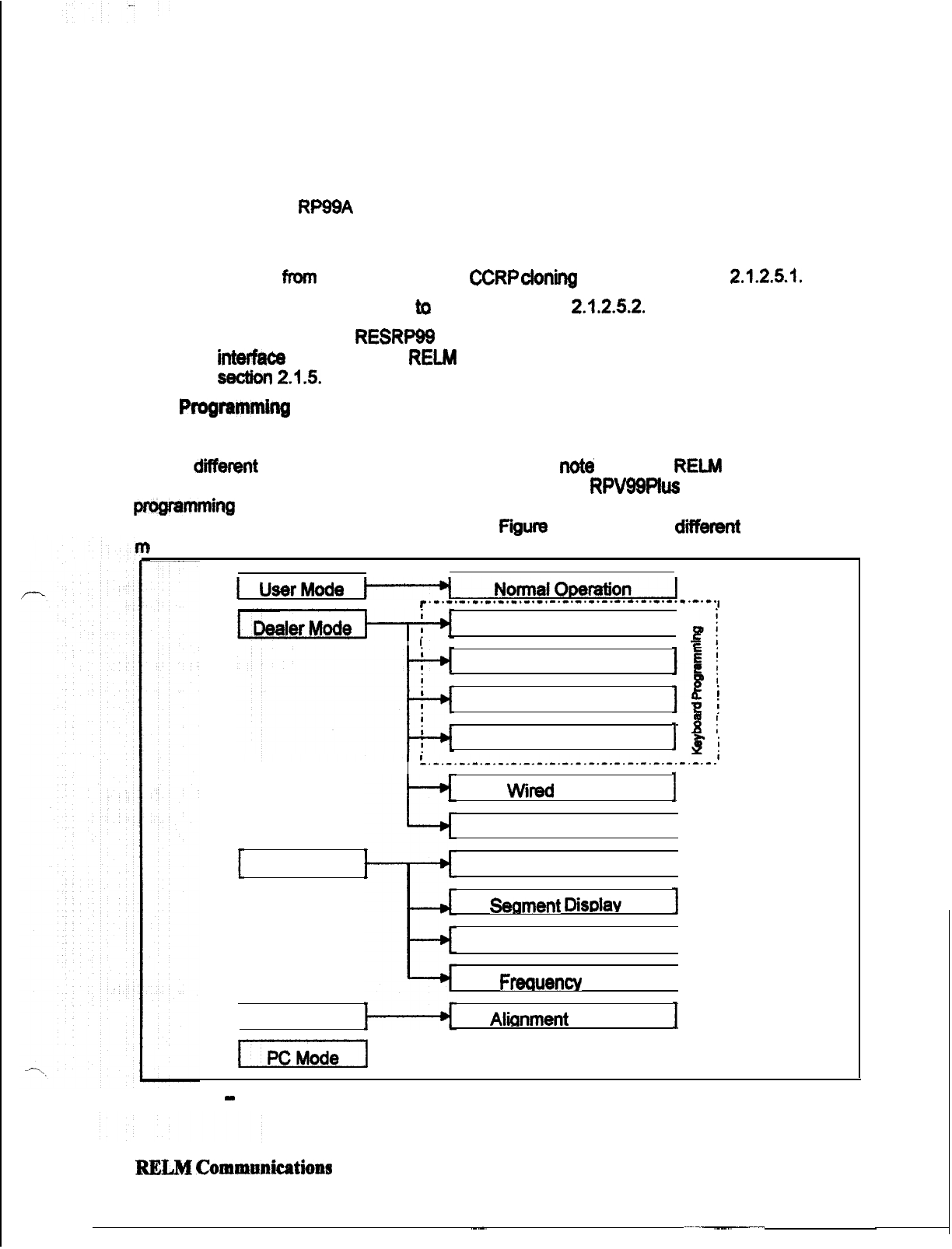
This manual contains information about field programming through the keypad of the RELM
Wireless
RP99APlus
serieshandheldVHFandUHFradiis. This manual is intendedfor use by
experiencedtechn’tins familiarwithsimilartypesof
mmerdal
gradecommunications
equipment. It contains service information and data for the equipment.
The following precautions are recommended for personal safety:
lDO NOT transmit until all RF connectors are secure and properly terminated.
lSHUT OFF and DO NOT operate this equipment near
elect&al
blasting caps or in an
explosive atmosphere.
lOnly qualified technicians should maintain this equipment.
1.2 Ww@tion
The RlWAPlus series radiis are
self-contaii
VHF or UHF FM Radiis covering the
frequency range of 148MHr to 174MHzfor VHF and
45OMHz
to 47OMHz for UHF. The radios
am
multi-channel and digitally synthesized using a single
aystal
for frequency control. The
RPg9APlus
series
incorporatean EEPROM for the
storaga
of channel frequency, CTCSS
Tone, DCS Code, Two-Tone, and Dual Tone Multiple Frequency/Automatic Numeric Identifier
(DTMFIANI) encode
information.
TheRPBAPlus
sertes
also include low-battery and
busy-
channei
indii.
Softkeyswitchescanbeprogrammedtocontrolchannelscan,DTMFstore
and send, mpeatertalk-around, and hi transmit power,
various
display modes, adding and
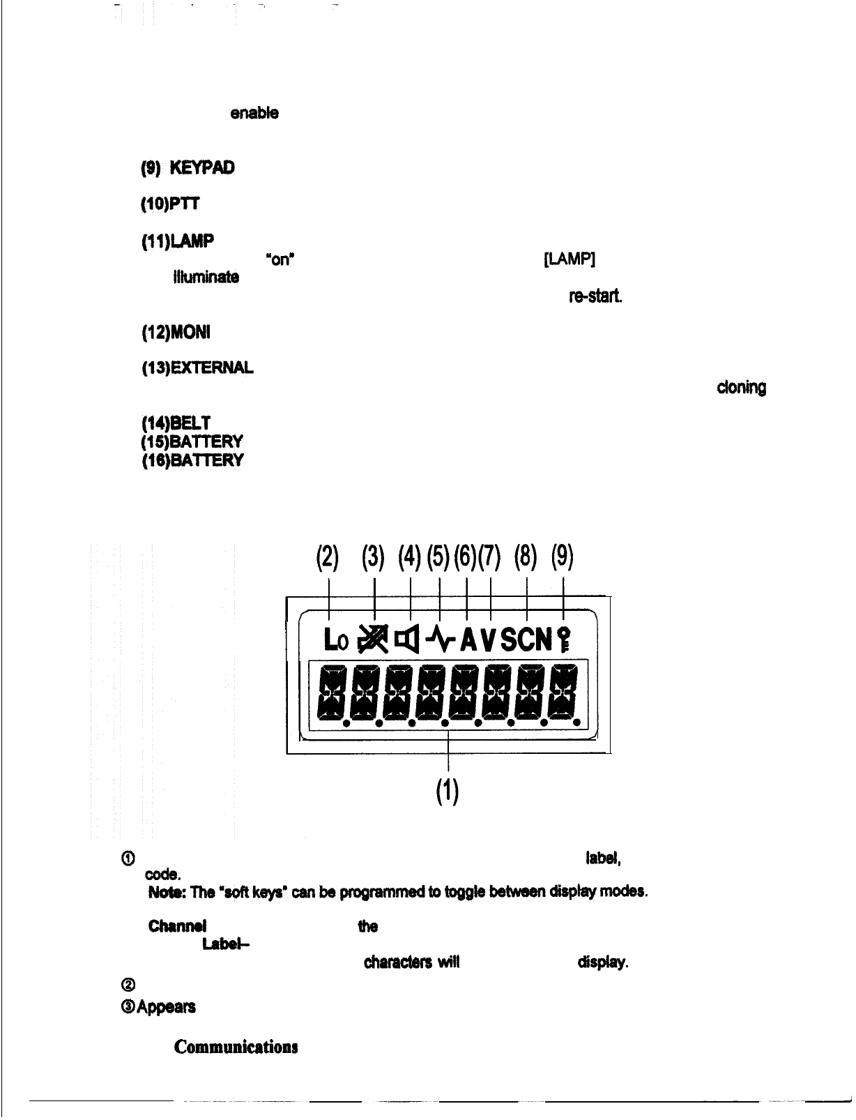
deleting channels from the scan list, key lock, and more. Status and channel information is
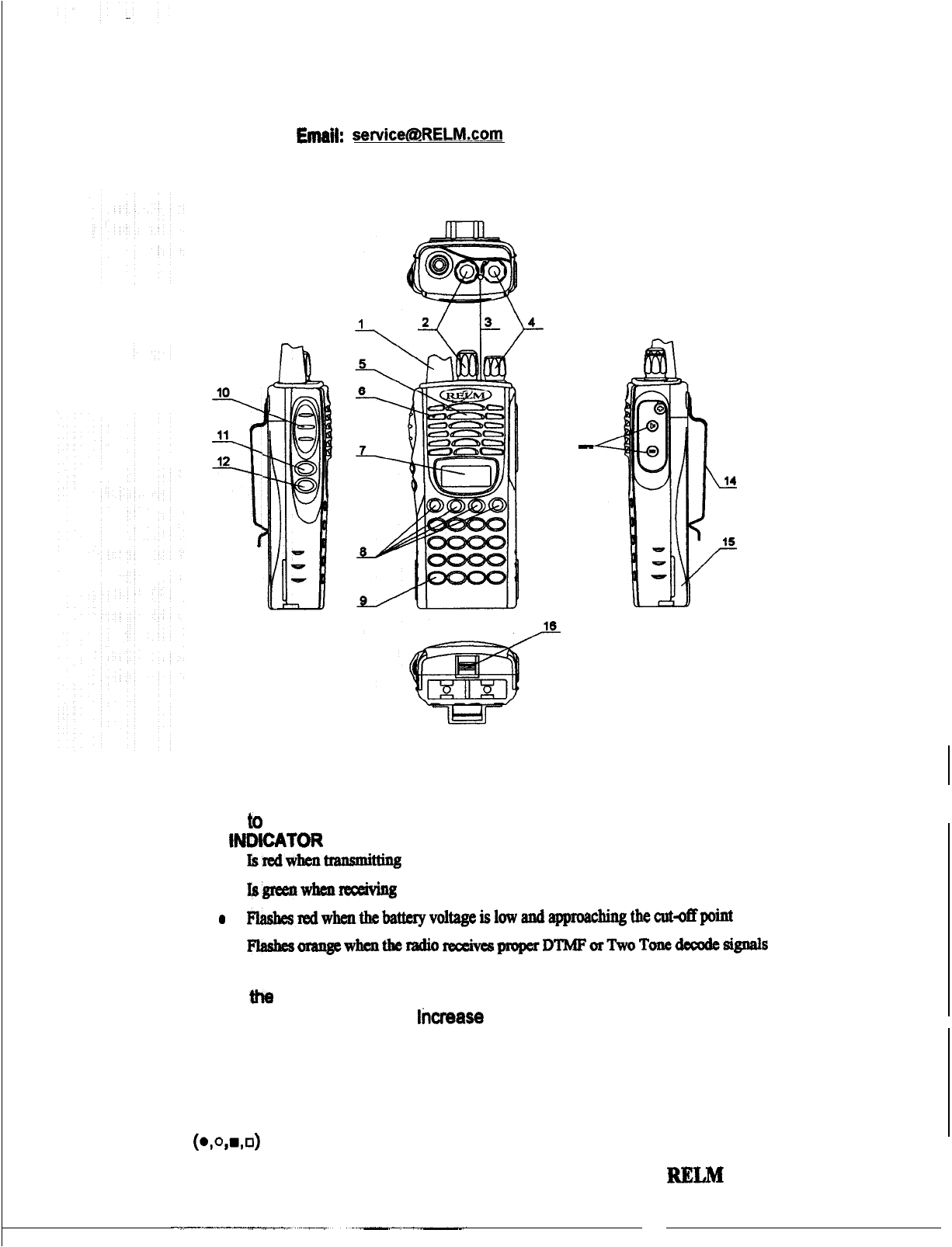
displayed over an alphanumertc liquid crystal display (LCD). Connectors am provided on the
side of the unit for an external antenna, microphone, speaker, and other optional accessories.
A
wida
vartety
of optional accessories are available for the RP hand held radii. Contact your
RELM Wireless dealer for complete information.
1.4
License
Requirmfmts
This equipment must be licensed by the Federal Communications Commission (FCC) before it
may be used. Your RELM Wireless dealer can assist you in filing the appropriate application
for the FCC, and will program each radio with your authorized frequencies and signaling
codes.
1.J
Teohnkal
Assistance
If you need technical assistance, contact a RELM Communications sewice technician:
RELM
Wides8 Corporation
AlTNtCustomer~ce
7100 Technology Drive
west
Molboume,
FL
32904
Phone: (800) 422-8281
FAX:
(321)
862-7988
RELM Communications
Page1

Email:
1.8
Controls and Indicators
-v
11
12
i
I
13
-
(1) ANTENNA
(2) CHANNEL SELECTOR KNOB
Used to select channel and squelch level. In addition, it can be programmed by the
dealer to delete undesired channels from scan list or to select a CTCSS frequency.
(3) LED INDtCATOR
.
lsredwhentl-tmmi~g
.
lsgltzellwften~
0
Fzasbcs~w~~t#lttcryvoltageislowandapproachingthe~~point
.
Flashesorangewhenthefadio rec&vespropcrDTMForTwoTonedecodegignais
(4) ON-OFF/VOLUME KNOB
Rotate the volume control knob clockwise to turn the unit ‘on” and fully counter
clockwise to turn the unit ‘off.
lkrease
or decrease the volume by adjusting the
volume control accordingly.
(5) SPEAKER
(8) MICROPHONE
(7) LCD
Used to display channel and operation status.
(8)
(o,o,w,o)
PROGRAMMABLE SOFT KEYS
Page 2
RELM
Communications

Used to
enable
or disable auxiliary functions. Press each key to enable its
corresponding function.
Used to enter, store, or send DTMF codes.
(1O)PTT BUTTON
Used to switch between transmit and receive mode.
(1l)iAMP
BUTTON,
Used to turn
“on”
or ‘off the LCD backliiht. Press the
[LAM4
button, the backlight will
Wminete
for about 5 seconds and then automatically turn off. During illuminating and
pressing any key, except the [LAMP] button, the timer will re-start. To turn “off the
backliiht, press the [LAMP] button again.
(12)MONI BUTTON
Used to monitor the selected channels.
(13)EXTERNAL SPEAKER-MICROPHONE JACK
Used to connect with external the speaker-microphone, programming cable, or cloning
cable.
(14)BELT CUP
(1J)BATTERY
(16)BAmRY
LATCH
1.7 LCD kons
I
I
0
Displays the selected channel number, channel frequency, channel
Iabe&
squelch level or DTMF
#de.
When selective call is enabled, messages received are also displayed here.
Nofir:The”softkeyo”canbsproorammed6otogglebetweendisptaymodes.
Channel Number- Displays channel number. Factory default
channel
Frequency- Displays the channel frequency.
Channel
Lab&
Displays characters of the channel label. Up to 16 alphanumeric characters can
be programmed. Any label over 8 charactars will scroll across the display.
Q
Appears when “low’ power is selected.
Q
Appe8rswhenthe selectedchannel is busy.
RELM Communhtions Page 3

@I
Appears when the [MONI] button is pressed to disable CTCSS, COCSS, OTMF, or Z-Tone.
Q
Appears
when the [MONI] button is pressed to switch the speaker on.
@
Appears when the selected channel is
in
the scan list. The radio only scans channels in the
scan list.
@
Appears while in the numeric entry mode when entering the channel labels through the
keypad.
Q
Appears in scan mode.
@
Appears when the keypad lock is “on”.
Page 4RELM Communications

2 FIELD (KEYPAD) PROGRAMMING
21 Programming
You can program the RP99A Plus series in four different ways.
A.
Using the unit’s keypad. See section 2.1.2.
B.
Cloning
from
unit to unit usinga
CCRP
ck)ning
cable.See section 2.1.2.5.1.
C. Wireless cloning from unit to unit. See section
2.1.2.5.2.
D. With a computer,
RESRPM
programming software, and a PCRP programming
interface cable. Contact RELM Communications for the software and cable. See
SBcbion
2.15
21.1 P~ramming Modes
Using the unit’s keypad, soft keys, and control knobs, the unit can be placed into one of
several
diierertt
programming modes. It is important to
not&
that only RELM authorized
dealers with qualified technicians am allowed to operate the
RPV99Plus
series radios in the
pf0gramming
mode and to change any programming content.
Fiium
2.1 shows the
dierent
programming
odes.
1
UserMode
1
~.~.~.~.~.~.~.~.~.~.““““-“‘-“‘-“’~.~.~.,
Global Settinas
I
I
I]
DTMF Settings
jt
i
i
i
Enhanced Global
i
e
i
Factory Mode
Test Mode
f--EizJ
Channel Settings
1
3
;
S!
-._.-.-.-._.---.-~-.-.-.-.-.-.-.-.-.-.-.-.-.-~
wiredCloning
I
Wireless Cloning
1
All Reset
I
All Sesment
DisDlav
Test
Band Set
I
Frequency
Scan
I
AlianmentSettinos
I
Figure 2.1
-
Programming Modes
RELM
Commani43tions
Page 5

Table 2.1 shows the functions that can be sat for each of the “Dealer Modes”. The dealer sets
the operations functions, channel frequencies, signal modes in accordance to the customer’s
neads.
The‘DealerMode”mustbeenabled“ON”intheradiobytheRESRPWWs editing
software before the dealer programming mode can be accessed.
1.
Monitor
2. Scan
3.
Dial
4.
Talk
Around
5.
Low
power
8. Priority
I.priority
Channel 8. Look Back A 0. Look Back B 10. Revert Channel 11 .TX Scan Delay
Time 12. Dropout Delay Time 13.Time Out Timer 14. Transmit Waning
15.
TOT Resume Time 18. TOT Reset Time 17. Squelch Level 18. Beep
IQSignalling 20. Battery Save 21. Selectable CTCSS 22. Delete/Add Enable
23.
24.
Digit
Time
25.
Inter
Digit
Time
26. Fir&
1
Time Wii CTCSS 20. PTT ID 30. Dial ID 31. Connect ID 32. Disconnect ID 33.
No.
Gf
DTMF Keys 34. DTMF Hold Time 35. Store 8 Send 38.D Key
Assignment 37, DTMF Signaling 38. Intermediate Code 30. Group Code 40. SQ.
~q&@“p?&M~;
UI,:
.,
,..,
i
,,,
~~~~~~~:~~~~~~~~
L~-~:“-~~;:~~;~:
45.
Tone 48. Tone
Duration 47. Channel
[a]
&signm&
Group 40.
Sofl
Group Key 2 [o]
Assignment
50.
Soff Label Size 48. Soft Key 1
Key
3
[a] Assignment 51.
Y~~~t.$
‘,
:l
r,
,,::
%&wz~~~;~~~
M
!pi;+
I. Channel Selection 2. RX Frequency 3. RX Tone Signaling 4. TX Frequency 5.
@Q;
#&& TX Tone Signaling 8.
DTMF&Tone
Signaling 7. ANI ID Enable 8.Scan
~~~~~ DeleteIAdd 0. Busy Channel Lockout IO. Clock Frequency Shift 11 .TX Power 12.
&*.\
<,“,Yl
#I,‘_
&n&i&h
13.
DTMF
ID
-de/RX
Z-Tone
14.
TX
Z-Tone
15.
Channel
La&j1
;r~~~3&v.,~
:ii+&&,~**
1
In this mode. data is cooied from one radio to another throuoh acable.
ln this mode, data is copied from one radio to another without cable by means
Table 2.1
-
Dealer
M=,-
InAne
2.1.2
Dealer
Ydes
-
Quick Referwtce
Place the unit in the programming mode by pressing and holding the [LAMP] and [
0
J
buttons,
switch the power
“on”.
After 2 seconds the radio enters the dealer mode and “SEL” appears on
the display.
[ZE:]
While in dealer mode, press the respective soft function key for the mode to be programmed.
See Table 2.2.
Page 6
RELM Communications

-
--
-
_-
-
.
--.
Table
2.2
-
DealerModesQuick
Reference
2.1.3 Dealer Mods Programming
2.1.3.1 Global
Settings
To place the unit
into the “Dealer Mode” for
adiing
tha global settings, do the following:
1.
While pressing and
hilding
the
[lAMPI
and [ 0] buttons, switch the power ‘on“. After 2
seconds the radio enters the dealer moda and
“SEC”
appears on the display.
[SE-:]
2. While in dealer mode, press [o] to enter the Global Settings mode.
Table 2.3 shows the function number and function options that can be selected while in this
.
mode. While in this mode, the Channel Selector knob is used to set functions “ON” or “OFF” or
to select the setting. After a function is sat, pressing the
[PlTl
button stores the setting and
increments the menu to the next function option. Also, when the
[PlTj
button is pushed, a
beep will sound to confirm the setting.
Pressing the [o] button at any time while reviewing the function options will pause the unit to
exit the selection mode and revert back to the dealer mode screen. The current function option
will not be stored if it was changed. After the complete option list has been cycled through,
“End” will appear on the display. To exit dealer mode, cycle the power “off’ and then back ‘ona.
To review or confinn the function settings while in the Global Settings mode,
press
and hold
the[MONI]buttunandturnthechannelelect knob.
-
Monitor Momentary
MONITOR
Disables the [MONI] button.
Signaling squelch (CTCSS, CDCSS, 2-Tone, or
DTMF) is temporarily disabled when the MONI
button is pressed.
Toggles between signal squelch and monitor
WI”,
II,“,
L-n RI”,.,
&
1
when the [MONI] button is momentarily pressed.
“:
:/,
1%
:
,,
Il;Uii:
:.j,
$
‘:.
‘j
Unsquelches the receiver while the [MONI] button
wessed.
.,
,,
~.
It=?:
,:
”
7’
;
,I
is
1
SCAN OFF
1
Dir
cables SCAN mode.
REZM
Communicutions
Page?
;

Disable
Disable
1-99
3flOms
-
1500ms
:lOOms steps)
SCAN TO ‘Time Operated’ SCAN.
DIAL OFF Disables the fDlAL1 kev.
the same as the receive frequency and the receive
frequency becomes the same as the transmit
1
frequency of the selected channel.
LO OFF
1
Disables the [LO] button so the user cannot select
the low power mode.
LO.~:::Cjj$::’ Enables the [LO] button so the user can toggle
iY
Q’&
~~&~;:la,~t(d;‘r~
,
+Y.:T.
:.“.,‘s:
,&:
mn
the
1~
and
high
transmit
p-r
mod=.
PRlO.:-CFF Disables the Priority feature.
PRIO
FIX
The Priority channel is a fixed channel selected by
the dealer. The user cannot change it.
PRIO
SEL
The priority channel can be selected by the user
while in the user mode.
~RICJ$&,!I~~V,
The fixed priority channel number. Note: “Fixed”
must be selected under Priority to enable this
PRlCH
gg
feature.
LBA 3oo Conditions: 1. The priority feature is enabled. 2.
,
The Scan feature is enabled. 3. The radio is in the
Page 8
RIZLM Communications

t
Last used
Selected
*
Talk Back SEL TALK
Priority
Priority + Talk Back
D.58
-
5.0s
(0.5s steps)
D.5s
q
5.0s
[Oss steps)
RELM Communications
LBB 500
LBB 5000
REV SEL
REV LSTU
REV
PRIO
PRI TALK
TSDT 0.5
+f@m!
i,,&W
TSDT 5.0
DODT 0.5
$JQppJfg ?
DODT 5.0
Conditions: 1. The priority feature is enabled. 2.
The Scan feature is enabled. 3. The radio is in the
scan mode. 4. The radio stops on an active
channel that is not the priority channel. 5. A signal
is detected on the priority channel, but the
signaling squelch (CTCSS, CDCSS,
~-TOM?,
or
DTMF) is not the same as the priority channel.
Look Back B is the time intervals that the priority
is checked for activity while receiving on the non-
priority channel.
Starts scanning or resumes scanning from the
selected channel. When scanning and the
PlT
button is pressed, it will transmit on the last
channel to be selected by the channel selector
even if a call is being received on another
channel.
Starts scanning or resumes scanning from the last
channel that received a call. When scanning and
the PTT button is pressed, it will transmit on the
last channel that received a call.
Starts scanning or resumes scanning from the last
channel that was transmitted on. When scanning
and the
PlT
button is pressed, it will transmit on
the last channel that was transmitted on even if a
call is being received on another channel.
Starts scanning or resumes scan from the
selected channel. When scanning and the PTT
button is pressed, it will transmit on the last
channel to be selected by the channel selector; or
if a call is received and the
Pll’
button is pressed,
it will transmit on the received channel (the
PlT
must be pressed before the Drop Out Delay Time
ends,
othewise
it will transmit on the last channel
selected).
Starts scanning or resumes scanning from the
priority channel. When scanning and the
PlT
button is pressed, it will only transmit on the
priority channel. When in the manual mode, the
radio will transmit on the selected channel.
Starts scanning or resumes scanning from the
priority channel. When scanning and the PTT
button is pressed, it will transmit on the priority
channel; or if a call is received on a non-priority
channel and the PTT button is pressed, it will
transmit on the received channel (the PTT must
be pressed before the Drop Out Delay Time ends,
otherwise it will transmit on the priority channel).
The period of time that the radio stays on a
channel after a transmission has been made
before it resumes scanning.
The period of time before the radio resumes
scanning after a received channel becomes
inactive.
Page 9

TOT OFF
OFF
3Os-300s
(30s steps)
TOT 30
The period of time that a user can transmit before
TOT.
.60 it stops transmitting. The unit beeps until the user
TOT
300 releases the
PlT
button to reset the TOT.
3~
,I
_,
.
OFF
is-60s
(1s steps)
;‘.;.
‘L’i:.
,..,
7;:
1TCTA
1
j
The oeriod of time that a user can transmit before
OFF IS-SOS
(1s
steps)
OFF
1~45s
(WlSTRP)
-I--
TOTA
60 it starts beeping. The unit beeps until the user
releases the PTT button to reset the timer.
‘..
.,,
;-:$+
,
:‘~~~,~~:;,,~,~.‘!~“:8,1;,
,’
,TQTKzF
Disabled
‘.::,
,,
..i;..,
i,
;
TOT;(““’
l’
1
After the TOT period, this is the period of time the
TOTK 60
radio must be in the receive mode before the PTT
button is active.
,I.
.‘.
-
,. ,.,
..i:
I
;’ Disabled -The
PIT
button can be pressed
1
T6’%-6FF:
1
immediately after released upon TX TOT timing
j..
,“,
vi_
o-o
(1
step increment)
‘-“.,~~~~~~~~~‘~.~:~.
::‘:;,
1’
od
TOTS
1
j
After the TOT DeriOd. this is the period of time the
TOTS 15
radio must be &r-keyed before the
PlT
button is
acttve.
Squelch level adjustment
-
Zero is minimum
squelch adjust and 0 is maximum squelch adjust.
No beeps will be heard when the keypad is
:~~~?~~~~~~~~~,~~~~~-~:~~~~o
j
:z&.!p>~
jl
;
,#&Z;,,l:
,:,
>.i.
.A<,
.,
,,
_,
>,
.:*,.‘
,..
:
:.:$
:.’
Enables the user to toggle through all CTCSS
tones when on a specific channel
-
affects RX and
Disable Disabled. Prohibii the user to add or delete
channels to or from the list of channels to be
I
scanned.
Pennits the user to add or delete channels to or
from the list of channels to be scanned.
Disable MODE OFF
I
I
Prohibii Dealer and Test modes
moDal
semngs
Page
10
RELM Communications

-.
_-
2.1.3.2.
DTMF Settings
To place the unit into the ‘Dealer Mode’ for ediing the DTMF settings, do the following:
1.
While
pressing and holding the (LAMP] and
[O]
buttons, switch the power “on”. After 2
[x-j
seconds the radio enters the dealer mode and “SEL” appears on the display.
2.
While in dealer mode, press
[O]
to
enter the DTMF Settings mode.
Table 2.4 shows the function number and function options that can be selected while in this
mode. while in this mode, the Channel
Selector knob and keypad (O-9, *,
#,
A-D)
are used to
set DTMF functions ‘ON” or
MOFF
or to select the setting. After a function is set, pressing the
[PTTJ’ button stores the setting and increments the menu to the next function option. Also,
whsn the
[purl
button is pushed, a beep will sound to confirm the setting.
Pressing the
[O]
button at any time while reviewing the function options will cause the unit to
exit the
sektlon
mode and revert back to the dealer mode screen. The current function option
will not be stored
lf
it was changed. After
tha
completa option list has been cycled through,
“W
will appear on the display. To exit dealer mode, cycle
the
power
=or
and than back “on”.
To review or confirm the function settings while in the DTMF Settings mode, press and hold the
[MONI]
button and turn the channel select knob.
(1 Oms steps)
I
I
5Oms
-
200ms
1
ICW
‘.i:.
50
1
OOms-1OOOms
RISE 100
(!5Oms
steps) ‘RISE
M“.
RISE 1000
100ms4000ms
RTQT 100
(50ms steps) T$liQT$
:$fj&
RTQT 1000
The period of time that each of the
programmed DTMF ANI digits
are
transmitted.
The period of time between each of the
programmed DTMF ANI digits
The period of time that the first digit of
the programmed DTMF ANI is
transmitted.
~
The
period
of time between un-
~
modulated TX carrier and when the
~
programmed DTMF ANI is transmitted.
~
The period of time
between
un-
modulated TX carrier and when the
oroorammed
CTCSS is transmitted.
].
Except for functions 31 and 32 that am set with the keypad.
L
When DTMF function
is enabled together with the Battery Save mode, and when CTCSS is used, the
transmit delay time should be set
*
300 ms.
REZM
Communications
Page
11

DIAL ID
CONNECT
ID3
DTMF HOLD
TIME
STORE 8
SEND
~D&!!bMq
irl
:d’..i”z
+&;
:.,
t
p,&&_4$F..I~
,,
*y
i
‘i
‘i:e
When transmitting, the programmed
,‘..,
,.:
. . . . . . .
..-
+!
:
,:‘.:
,...,.
:
1,
;
i
.-
’
‘+’
Connect or Disconnect DTMF
ANI
will
,.
.,-’
;,,;ip’
:::;,*
. .
.:
i
k...
‘,
<,
,
..wl
.k
;,
”
”
.,
”
]
~.&~“~
,:..;
;!‘#,
:.-
.,.
,
,:,,
.-
‘i not be sent when [DIAL] and the
z,.,
;..s;-:
b; T
“::
I’$@!
pt;:p
,q
_:‘i
.
,-(
:
.’
.,
..,:
1
/,,,
‘i’!
‘I
$
q&-p
P.IDBEGIN
res ective
.~
or
‘f
key is pressed.
Connect When transmitting, the programmed
Connect DTMF ANI will be sent when
[DIAL] and
‘*
key is pressed.
Disconnect P.ID
END
When transmitting, the programmed
Disconnect DTMF ANI will be sent
when [DIAL] and
‘#”
key is pressed.
When transmitting, the programmed
Both P.ID BOTH Connect or Disconnect DTMF ANI will
be sent when [DIAL] and respective
‘*
or
‘f
key is pressed.
-,Di#?fe
I:!;
i.;i,?
.:
:,
,+
z:..;Rt
~&1D:&lFF:~~~ Disabled
ON
1
D.ID
ON
When transmitting, a stored DTMF ANI
code will be sent when [DIAL] and a
memory location key is pushed. An
ANI number must be programmed in
the user mode. Up to 10 memory
locations can be used (keys 0 through
I
and SC key is pressed. Note: Only the
last five digits of the ANI number will be
and
‘+
key is pressed. Note: Oniy the-
last five digits of the ANI number will be
D)
-
C, D,
l
and #.
Disable
DHT OFF
No Hold Time
~,
r
2 seconds after
the last number on the DTMF key is
manually selected, but only if the PTT
button is released after the last
number.
Does not allow Auto ID numbers to be
3
‘PJDBEGIN’ is momentarily displayed when entering this setting.
4
‘P.ID END” is momentarily displayed when entering this setting.
Page 12
RELM Communications
--.
-.-
.-.-
___--

-
--
DTMF
SIGNAL .ING
O-9
A-D
1A-D
OFF
Is
-
15s
(1s steps)
DKEYA 1
DKEYA 16
DTMF OFF
DTMF CSQ
DTMF SEL
MC 0
MC 9
IMC A
IMC D
IMC E
fMB”
F
7,.
,:
:
I
@if?
qp
GRPC A
GRPC D
GRPC E
GRPC F
40 OFF
SART 1
SART 10
SART 15
When transmitting, the radio transmits
an w-modulated signal for the
programmed time when [DIAL] and the
D key is pressed.
Disabled
When the respective DTMF code is
received on a channel, the radio will
ring for approximately 10 seconds and
receiver audio will open. The ringing
can be terminated by the user
responding with a transmission or by
pressing the MONI button.
Conditions: 1. The receiving radio must
have a three digit DTMF ID Code
programmed. 2. The transmitting radio
must be programmed with a 3-digit
DTMF ID code, a ldigit Intermediate
Code, and a I-5 digit Message code.
(i.e. 123 #4567). The whole
message string is sent when the [DIAL]
key is pressed.
The digit that separates the 3 digit
DTMF ANI code to be decode and the 1
to 5 digit message (Ex. 123
#
4567)
Disabled
Identifies that a DTMF Select call is for
a group, not for an individual.
Disabled
After a DTMF signal is decoded, it is
the period of time before the squelch is
reset to the ready state of decoding
another DTMF signal.
5
When changing and storing a ‘DTMF SIGNALING” option, the ID CODE setting in channel mode will be
met to 7XW; and the 2-Tone settings will be reset to V”.
RELM
Communications
Page 13
/
J

-able
2.4
-
Dealer
Modr
CALL
ALERT/
TRANSPOND
Disabled
Call Alert
TRANSPOND (Call
Alert).
TRANSPOND (ID
code)
TRANSPOND
(Transpond Code)
~TMF Settings
CAT OFF
’
_
CAT RING
CAT BEEP
CAT CALT
CAT
IDCD
CAT TRCD
Disabled
The radio flashes the LED indicator and
rings when it decodes a two-tone or
DTMF signal.
The radio flashes the LED indicator and
beeps when it decodes a two-tone or
DTMF signal.
The radio flashes the LED indicator and
rings when it decodes a two-tone or
DTMF signal; and it transmits the alert
back to the sending radio.
The radio llashes the LED indicator
when it decodes a two-tone or DTMF
signal. If DTMF is used, the receiving
radio also transmits the DTMF ID code
(listed in the Channel programming)
back to the sending radio.
The radio flashes the LED indicator
when It decodes a two-tone or DTMF
signal. If DTMF is used, the receiving
radio also transmits the DTMF ID code
(listed In the DTMF Auto ID that is
stored in location 0) back to the
sending radio. If no DTMF Auto ID is
stored in location 0, the receiving radio
will not transpond.
If any of the functions in Table 2.3 and Table 2.4
are
set to “Off”, the related setting shown in
taMi
2.5
can be set, but tha setting will not be recognized.
Page 14
RELM Communications

-.
_
--
2. [SCN]
19.
Look Back B
1
10. Revert CH
Il. Dwell Time
12. Dropout Delay Time
14. TOT Pm-Alert
15. TOT Rekey Time
-
16. TOT Reset Time
31. Connect ID
1
32. Disconnect ID
1
29. PTT ID is OFF or connected and 30. Dial ID is
&&&$:,
‘;.> ‘2;.
)?
,’ ;
::
&&@&
d#@$
_,
DTMF 37. DTMF sianalina is OFF
TO I 7. Prioritv is fixed or selected.
I
Fiied, Selected 2. [SCN] is OFF
6. Priority is OFF or fixed.
6. Priority is OFF
6. Priority is OFF
Priority, Priority + Selected 6. Priority is OFF
12.lSCNl is OFF
I
1
2. fSCN1 is OFF
I
I
13. Time Out Time is OFF
I
I
13. Time Out Time is OFF
I
13. Time Out Time is OFF
29.
PlT
ID is OFF or disconnected and 30. Dial ID is
1OFF
37. DTMF signaling is OFF or is code SQ.
37. DTMF signaling is OFF.
Tabfe
2.6
-
Disabled
Function
Conditions
2.1.3.3
Enhanced Global
Wings
To place the unit into the “Deafer Mode” for editing the enhanced globa! settings, do the
following:
1.
While pressing
and
holding the (LAMP] and
[O]
buttons, switch the power %n”. After 2
seconds the radio enters the dealer mode and “SEL”
appears
on the display.
2.
While in dealer mode, press [a] to enter the Enhanced Global Settings mode.
Table 2.6 shows the function options that can be selected while in this mode. While in this
mode, the Channel Selector knob is used to set functions “ON” or ‘OFF” or to select the
setting. After a function is
set, pressing the
[PTTI
button
stores the setting and increments the
menu to the next function option. Also, when the
[PllJ
button is pushed, a beep will sound to
confirm the setting.
Pressing the [o] button at any time while reviewing the function options will cause the unit to
exit the selection mode and revert back to the dealer mode screen. The current function option
will not be stored if it was changed. After the complete option list has been cycled through,
“End” will appear on the display. To exit dealer mode, cycle the power
“off’
and then back ‘on”.
RELM Communications
Page 15

T
O
rev@w or confirm the
fun&on
settings while in the Enhanced Global Set mode, press and
hold the [MON1] button and turn the channel select knob.
Page 16
0.5
-
10s
(0.1s steps)
Dliiplpy
-‘,
_,.
.l’...“‘:
::,fWitark
‘,;Js,;,ll
.,-
cc’,
i,.
ii
.$‘
y,:;
Tii
i;;
:,,j<
~:
,;~;,c>;I;,;:;’
.,!,
.,..
:
,:
r
(_
_’
‘,:
1;,
.b,,
;
/
:.‘;,
.<,;;y.+.:
;‘$i;:i
“::*‘-,:”
.
,:;
.$
:+:.r
,.
,;
.:
;,,
,,
,.
: :
+’
C,‘:.
-:-
GRPT OFF Group Tone set to “OFF
GRPT A
Group code set to the ‘A’ Tone.
GRPT B
Group code set to the ‘B” Tone.
Group Tone duration.
GTDUR 0.5
Off,l-16
(1
step)
GTDUR 10.0
SIZE OFF The channel label display mode is disabled.
SIZE
1
SIZE
16
The number of channel label characters that
can be displayed.
No Function
Scan
Dial
Talk
Mound
Law
PoweJr
Kl OFF
The function key is disabled.
Kl
SCAN The function selected will be assigned to this
Kl DIAL
soft key.
Kl
TARE
._
-_-
Kl
Lo
Display Label
y
Frequency
1Kl
1
Kl
Variable
C
.
3-r
SQL
No Function
Scan
Dial
Talk Around
,
.I.
1
Kl
. . .
VQT
Kl SQL
K2 OFF The function key is disabled.
K2 SCAN The function selected will be assigned to this
KZDIAL .
soft key.
K2 TARE
Low Power
Display Label
Displa
y
Frequency
Display Mode
Scan Add/Del
Key Lock
Variahla
i
1K2LO
IK2
DCHAR
IK2
DFREQ
KZDMODE
KZSADD
K’
KLOCK
VQT
1
-,.-w.-
41
SQL
No Function K3CiQL
._-. -..-
_._..
Scan
Dial
Talk Around
Low Power
Display Label
Displa
y
Frequency
Display Mode
.-
IFF
The function key is disabled.
K3 SCAN The function seiected will be assigned to this
K3 DiAL soft key.
K3TARE
K3 LO
1K3
DCHAR
Ir(
(3
DFREQ
I
K3DMODE
Scan Add/Del
Kev Lock
1
K3SADD
1
K.?
KLOCK
,
a.”
3-r
t
KR
Variable C.
SQL
No Function
Scan
.
._
VQT
K3 SQL
K4 OFF
K4 SCAN The function key is disabled.
The function selected will be assigned to this
RELM Communications

l’abk2.6
-
Dealer
Mods Enhanced
Global
Settings
2.1.3.4 Channel Settings
70
place the unit into the “Dealer McxW’ for editing the channel settings, do the following:
1.
while
pressing and holding the [LAMP] and
[O]
buttons, switch the power “on’. After 2
seconds the radio enters the dealer mode and %EL” appears on the display.
2. While in dealer mode, press
[m]
to enter the Channel Setting mode.
Table 2.7 shows the fUnction options that can be selected while in this mode. While in this
mode, the Channel
Sekctor
knob is used to set functions “ON“ or “OFF” or to select the
setting. After a function is set, pressing the
[Pm
button stores the setting and increments the
menu to the next function option. Also, when the [PTTJ button is pushed, a beep will sound to
confirm the setting.
Prassing the
[a]
button at any time while reviewing the function options will cause the unit to
exit the selection mode and revert back to the dealer mode screen. The current function option
will not be
s&red
if it was changed. After the complete option list has been cyded through,
‘End” will appear on
tha
display, To exit dealer mode,
cyde
the power ‘off” and then back
*on”.
RELM
Commnnicatiaas
Page
17

-
160.06600.
100.00@~.
100.00~
16~.00000
OFF
QT
61.0
QT 67.1”
DQTBN
DQTO23]
DQTWN’
l6o.ooooo.
Channel to be programmed.
No receive or transmit frequency
Pressing the
[o]
button toggles no frequency to the start
of the reoeive frequency if the channel is blank
Rotating the channel selector will raise or lower the
frequency by 2.5kl-i~ or 6.25KHz increments. If a decimal
point is shown next to the last digit of the frequency, then
the increment is 6.25Kl-l~; if there isn’t a decimal point
shown next to the last digit of the frequency, then the
increment is 25KHz. Pressing the
[o]
key will toggle the
increment size between 2.5kHz and 6.25KHz.
Holding in the lamp key and rotating the channel selector
will raise or lower the frequency by
IMHz
increments.
Disables CTCSS or DCS
Selecting the
[u]
key switches it from OFF to the first
CTCSS tone. Rotate the channel selector to move the
tone frequency up or down in 1 Hz increments until the
desired tone frequency is reached. If there isn’t an
asterisk shown next to the last digit of the frequency, then
the increment change is 1Hz; if there is an asterisk
shown next to the last digit of the frequency, then the
increment change Is 0.1 Hz. Pressing the
[o]
key will
toggle the increment size between 1 Hz and 0.1 Hz.
Selecting the
[III]
key again switches lt from CTCSS to
the first DCS tone. Rotate the channel selector to move
the DCS code up or down until the desired code is
reached. The last alpha character will be an
‘N”
(non-
inverting) or ‘I” (inverting). Pressing the [O] key toggles
the
‘N’
and
‘I”.
Pressing the
[o]
key will toggle the DCS
selection between ‘standard’ and *non-standard’ DCS
codes. If there isn’t an asterisk shown next to the last
digit of the DCS code, then the DCS tone selection is
‘standard’; if there is an asterisk shown next to the last
digit of the DCS code, then the DCS tone selection is
‘non-standard”. Selecting the
[II]
key again switches it
from DCS to OFF.
No transmit frequency. Receive only.
Pressing the
[o]
button toggles no frequency to the start
of the transmit frequency if the channel is blank
Rotating the channel selector will raise or lower the
frequency by 2.5kl-l~ or 6.25KHz increments. If a decimal
point is shown next to the last digit of the frequency, then
the increment is 6.25Kl-l~; if there isn’t a decimal point
shown next to the last digit of the frequency, then the
increment is 2.5KHz. Pressing the
[a]
key will toggle the
increment size between 2.5kl-l~ and 6.25Kl-l~.
RELM Communications
--
This manual suits for next models
1
Table of contents
Other RELM Transceiver manuals
Popular Transceiver manuals by other brands

Technisonic Industries Limited
Technisonic Industries Limited TFM-138 Installation and operating instructions

Yaesu
Yaesu FT-857 series installation guide

Kenwood
Kenwood TS-440S Service manual

Yaesu
Yaesu FT-480R Maintenance service manual

Albrecht
Albrecht AE 550 instruction manual

HP
HP MSA 2040 installation instructions