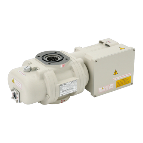
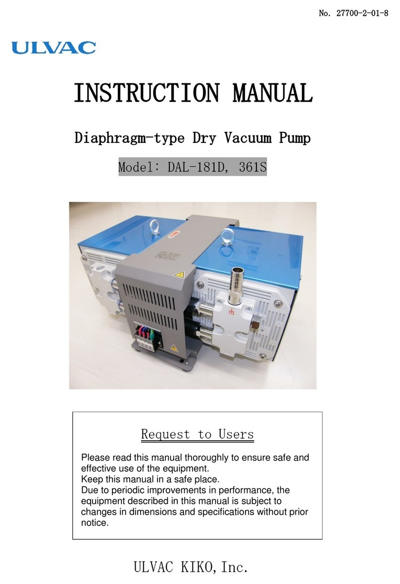
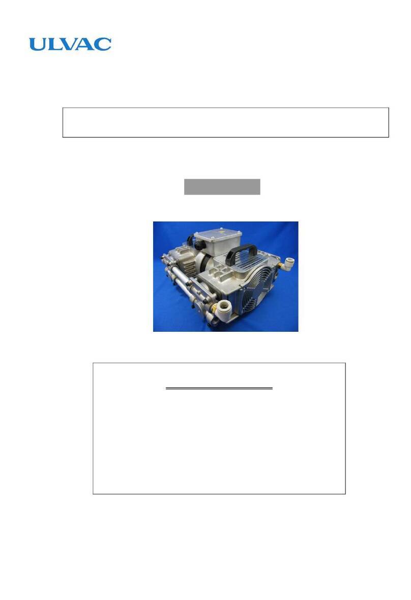
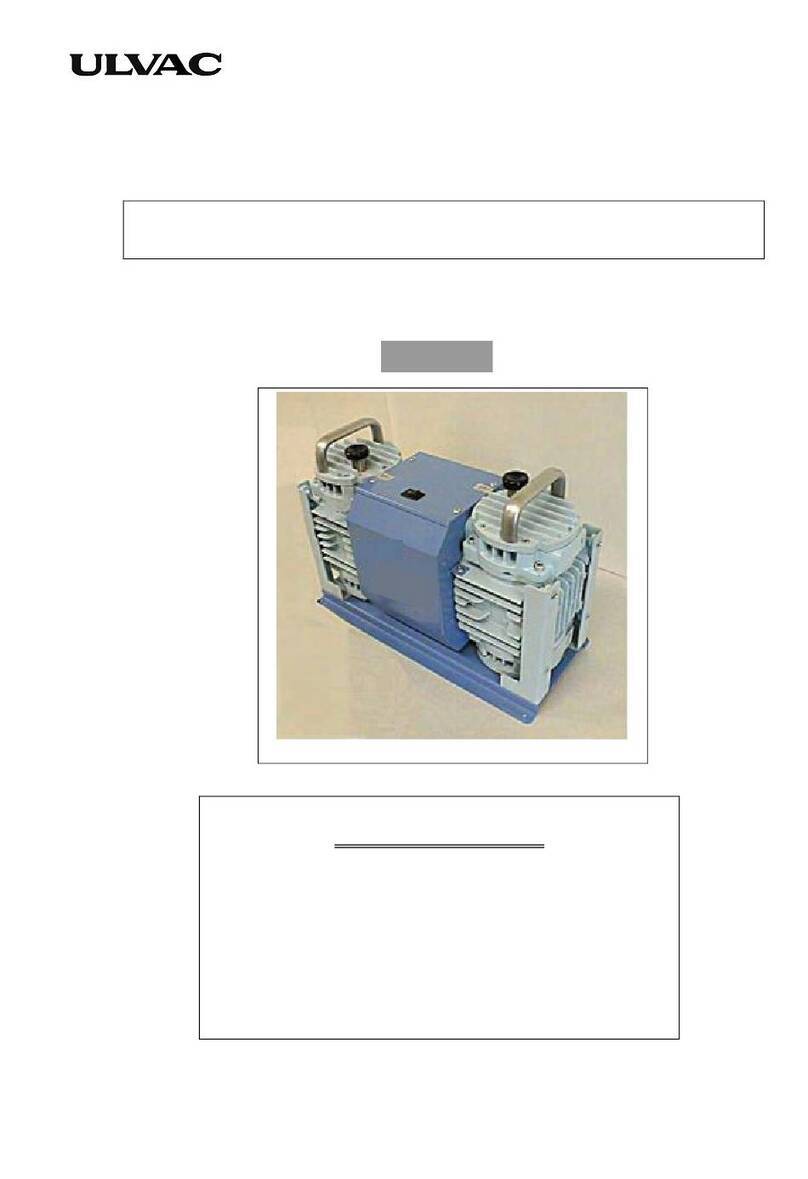
Ulvac G-5DA User manual

No.P8129-2-02-13
Instruction Manual
for
Direct-Drive Oil Sealed Rotary Vacuum Pump
Model
G-5DA,G-10DA
Before using the product, be sure to read this manual.
Keep this manual in a place where it can be referred to
at any time and look after it carefully.
The contents of this instruction manual are subject to
change without prior notice due to improvements in
performance and the functions of the product.
ULVAC KIKO,Inc.

1
0.Preface
0.1 Before using this pump
We, ULVAC KIKO,Inc. thank you for purchasing our vacuum pump. When receiving
our vacuum pump, please confirm the product is the same Model No. as you ordered.
Also, check to make sure there are no damages.
To ensure a long life for this pump, read this manual carefully prior to
installation, operation, and maintenance. Also, pay attention to
ascertain the details of safety, specification, and operational
precautions of this pump.
Copyright by ULVAC KIKO,Inc. All right reserved. All material in this
manual shall not be copied without permission by ULVAC KIKO ,Inc. Printed
in JAPAN.

2
0.2 Safety precautions (General expression)
Safety precautions are identified in this manual using headers DANGER, WARNING,
CAUTION, and NOTE.
"Danger" Indicates major hazardous situations, which present an immediate
threat of death or serious injury.
"Warning" Indicates hazardous situations, which may present a potential
to death or serious injury.
"Caution" Indicates hazardous situations where a potential hazard or
unsafe practice could cause personal injury or equipment damage.
"Note" Indicates undesirable situations where a potential hazard could
cause equipment damage or abnormal operation.

3
0.3 Safety precautions
When evacuating toxic or inflammable gas, there may be danger of leaking
gas from parts besides inlet port. Practice cautionary steps when working
any kind of gases.
After evacuating toxic gases, the inside of pump and pump oil is
contaminated and toxic. Therefore, handle pump with care during
maintenance.
Do not overhaul or repair this pump.0nly authorized maintenance personnel
should handle this pump to avoid ignition, abnormal action, and electric
shock.
Switch off power before checking or repairing the pump to avoid any
problems (electric shock or personal injury) caused by suddenly starting
up.
Connect an electrical wire cord to ground potential terminal tightly to
avoid electric shock caused by mechanical trouble or electrical leakage.
Do not plug exhaust port or place any materials inside of exhaust port,
because it will reduce pumping speed during operation. Pump explosion,
oil level gauge bursting, or motor over loading are consequences of
excessive pressure inside the pump. This pump is not a compressor. The
maximum pressure inside this pump is 0.03 MPa (GAUGE).

4
Do not use this pump in an explosive or flammable atmosphere. It may cause
personal injuries or fires.
Do not insert objects, fingers, or another pump body parts into the inlet
port. It may cause electric shock, personal injuries, or fires.
Do not touch the motor body, shaft, or shaft coupling joint during
operation. It may cause personal injuries.
Do not place flammable objects around the pump. It may cause fires. Also,
do not place obstacles around the pump so as to obstruct cooling air.
Abnormal temperature rising may cause burns or fires.
Do not touch the motor while the pump is in operation or when the pump
is still hot immediately after it stops. Touching it will result in burns.
Electric wiring should be carried out in accordance with Electric
Regulation and Instructions. Miswriting may cause fires.
Switch off electric power right away in case of a malfunction to prevent
any troubles. In the case of a malfunction, contact your local agent or
ULVAC KIKO,Inc. Sales and Service Center immediately.
Do not start the pump without pump-oil. Failing to do so will lead to pump
destruction.

5
0.4 Acceptance and store of product
0.4.1 Acceptance of product
We delivered the pump with the utmost care. After unpacking, please check
up and confirm items as shown below,
(1) The pump is what you ordered.
(2) Spare parts (single use of pump oil, optional parts)
(3) Any damages during transportation.
(4) Any loose screws and nuts.
If you find any abnormal circumstances, please contact your local ULVAC
KIKO,Inc. Sales or Service Center.
0.4.2 Store of product, Installation, Operating condition
This pump is a type of precision equipment; therefore, it is necessary
to satisfy the following items for store product.
(1) Operational temperature and humidity : 7~40°C , 85 % RH >
(2) Installation place should be at an altitude no higher than 1000m above
sea levels for storing or operation.
(3) Required conditions while storing or operating
a. Do not use corrosive or explosive gases.
b. No areas with high moisture.
c. No areas with dust particles.
d. Use indoors only.
e. Do not pile up, or lay on its side.
f. Keep out of direct sun light.
g. Keep away from heat source.
Do not treat with force, or lay on its side. It may cause damage.

6
0.5 Protective precautions
・100 volt ,single phase,50/60 Hz motor is used for this pump.
・A built-in type thermal protector is equipped for the motor.
・Additional(leakage, etc)protectors are recommended.
Do not apply any voltages other than specifically rated for the motor of
this pump. The over-load protector does not operate normally,
consequently it may cause burning the motor or firing.

7
CONTENTS
0.Preface ・・・・・・・ 1
0.1 Before using this pump ・・・・・・・ 1
0.2 Safety precautions (General expression) ・・・・・・・ 2
0.3 Safety precautions ・・・・・・・ 3
0.4 Acceptance and store of product ・・・・・・・ 5
0.4.1 Acceptance of product ・・・・・・・ 5
0.4.2 Store of product, Installation, Operating condition
・・・・・・・ 5
0.5 Protective precautions ・・・・・・・ 6
1.For safety operation ・・・・・・・10
1.1 Hazardous of product and safety precautions ・・・・・・・10
1.1.1 DANGER Leakage of hazardous gases and materials ・・・・・・・10
1.1.2 WARNING Electric shock ・・・・・・・10
1.1.3 WARNING Warning explosion ・・・・・・・11
1.1.4 CAUTION High temperature ・・・・・・・11
1.2 Safety data sheet(SDS) ・・・・・・・12
2. General description of the pump ・・・・・・・13
2.1 Principal features ・・・・・・・13
2.2 Dimensional drawings ・・・・・・・14
3. Setting up ・・・・・・・15
3.1 Installation ・・・・・・・15
3.2 Oil charging ・・・・・・・15
3.3 Vacuum tubing ・・・・・・・17
3.4 Electric wiring ・・・・・・・17
3.5 Fluctuations in the power voltage and frequency ・・・・・・・18

8
4. Operational instructions ・・・・・・・20
4.1 Operational precautions ・・・・・・・20
4.2 Start up operation ・・・・・・・21
4.3 Shut down operation ・・・・・・・22
4.4 Start up procedures in cold climate ・・・・・・・22
4.5 Thermel protector ・・・・・・・23
4.6 Setup oil mist trap (option) ・・・・・・・23
4.7 The restriction in an operation of
oil mist trap (option) ・・・・・・・24
5. Specification ・・・・・・・25
5.1 Ultimate pressure ・・・・・・・25
5.2 Pumping speed ・・・・・・・25
5.3 Required electricity ・・・・・・・25
6. Maintenance, inspection, repair ・・・・・・・27
6.1 Maintenance ・・・・・・・27
6.2 Scheduled inspection ・・・・・・・27
6.3 Oil change ・・・・・・・29
6.4 Replacement of the coupling ・・・・・・・31
6.5 Trouble shooting list ・・・・・・・32
7. Product disposal ・・・・・・・34
8. Maintenance parts ・・・・・・・35
8.1 Maintenance parts list ・・・・・・・35
8.2 Disassembly drawing ・・・・・・・36
Warranty
Safety Data Sheet(SDS)
Check sheet for repair
Sales and Service Centers

9
DRAWING AND TABLE LIST
Fig-1 General assembly drawing of G-5DA ・・・・・・・14
Fig-2 General assembly drawing of G-10DA ・・・・・・・14
Fig-3 Oil charge to rotary vacuum pump ・・・・・・・16
Fig-4 Vacuum pumping system diagram ・・・・・・・17
Fig-5 Change region of the voltage and frequency ・・・・・・・18
Fig-6 Characteristics of vacuum pumping speed ・・・・・・・26
Fig-7 Characteristics of motor power ・・・・・・・26
Fig-8 Replacement of the coupling ・・・・・・・31
Fig-9 Disassembly drawing of G-5DA ・・・・・・・36
Fig-10 Disassembly drawing of G-10DA ・・・・・・・37
Table-1 Specification ・・・・・・・13
Table-2 Characteristics of the thermal protector ・・・・・・・23
Table-3 Scheduled inspection ・・・・・・・28
Table-4 Trouble shooting list ・・・・・・・32
Table-5 G-5DA Maintenance parts list ・・・・・・・35
Table-6 G-10DA Maintenance parts list ・・・・・・・35

10
1.For safety operation
1.1 Hazardous of product and safety precautions
Before operating or inspecting the pump, read this manual carefully. And pay
attention to ascertain the detail of potential hazardous and preventive
procedure so that must be operated or inspected the pump.
1.1.1 Leakage of hazardous gases and materials
Cause Preventive Procedure
Leakage of toxic or inflammable
gases.
⇒Before evacuating gases to the pump
inlet, dilute them to safety level.
Injuries of skin by direct contact
with contaminated oils or adhered
hazardous materials of the pump
body when checking or disposing
dispose the pump.
⇒① After wearing suitable protector for
evacuating hazardous materials, check
or abolish the pump.
② Before checking or disposing the pump,
non-hazardous treatment must be
requested for the authorized
professional specialist, then check or
the pump.
③ Disposal must be requested for the
professional specialist authorized by
the administration.
1.1.2 Electric shock
Cause Preventive Procedure
Electric shock by touching
electrical bare portion of the
motor when electric power is on.
⇒① Switch off power certainly before
electric wiring Connect electrical
wire cords to ground potential
terminals tightly.
② Switch off power before inspection or
removing.
③ Do not insert objects, fingers, or any
thin bars into the inlet port.

11
1.1.3 Warning explosion
Cause Preventive Procedure
Pump explosion is consequence of
excessive pressure inside the pump.
⇒The maximum pressure inside the pump is
0.03 MPa (GAUGE).
If inlet pressure of the pump is higher than 0.03
MPa (GAUGE), eliminate any objects which may
cause obstruct gas flowing to the inlet port.
When using oil mist trap, exchange or clean
them to avoid gas flowing.
1.1.4 High temperature
Cause Preventive Procedure
Burn at high temperature. ⇒① Temperature of the pump is high as shown
below
pump body → 70 ~ 80℃
motor → 70 ~ 80℃
② High temperature surface of the pump may
cause to burn as a result of direct skin contact
by accident. Do not touch the pump body
during operation. Inspection should be carried
out after stopping and cooling down the
pump.

12
1.2 Safety data sheet (SDS)
The chemical material, which is applied or possible to contact when operating
this pump are described. Read this manual carefully to understand
characteristics of the chemical material (vacuum pump oil), which is described
on SDS sheet. When applying other vacuum pump oils besides the description in
this manual, contact your local ULVAC KIKO,Inc. Sales and Service Center.
SDS presents the reference information of hazardous chemical material to
keep safety precautions. When handling the pump oil, it is necessary to
take proper and practical treatments, which are adapted handling the oil.
After understanding the above mention, these treatments must be done.
Therefore, SDS is a not safety warranty.

13
2.General description of the pump
2.1 Principal features
This oil rotary vacuum pump is a sliding vane type (so called Gaede type), with
direct driven motor. As it is a small sized, lightweight, and simple structure,
it is easy to maintain or over-haul.
Table-1 Specification
Model Unit G-5DA G-10DA
Type Sliding vane 2 stages
Pumping speed L/min 50Hz 5 10
60Hz 6 12
Ultimate pressure Pa 6.7 1.3
Motor (W), Poles 40(4) 60(4)
Volts V 100 100
Full load current A 50Hz 0.92 1.38
60Hz 0.73 1.22
Motor revolution r/min 50Hz 1,250 1,250
60Hz 1,550 1,565
Pump oil Recommended SMR-100
Capacity,(mL) 180 250
Note 1. Ultimate pressure indication by Pirani gauge.
2. Vapor pressure, viscosity, or characteristics of vacuum pump oils
are different respectively. Our recommended oil is SMR-100.

14
2.2 Dimensional drawings
Fig-1 General assembly drawing of G-5DA
Motor ; Single phase, 100V, 40W, 4Poles, capacitor run
Weight ; 5.0kg(with motor)
Fig-2 General assembly drawing of G-10DA
Motor ; Single phase, 100V, 60W, 4Poles, capacitor run
Weight ; 5.5kg(with motor)

15
3. Setting up
3.1 Installation
Installation must be done at a place of low moisture, low dust particle, and
also level. The layout arrangement should be considered for setting up, overhaul,
checking, or cleaning the pump. When setting up the pump in any systems, pay
attention to temperature in atmosphere. Mount rubber isolator to absorb
vibration from the pump. On the environmental condition, refer to 「0.4.2 Store
of product」.
Do not tilt, lay its side, or operate up side down. It may cause damage.
The pump must be placed on a level place in an upright position as shown
in Fig-1,Fig-2.
3.2 Oil charging
Remove the Exhaust port, and then fill the oil (one time charge) to the pump
or recommended oil (SMR-100) up to specified quantity through the Exhaust port.
In first oil charging, pour the oil up to maximum scale of oil gauge. Then, attach
the exhaust port. (Refer to Fig-3) Oil quantity must be checked or adjusted to
keep the oil quantity is always in the range of oil gauge during operating the
pump.
Improper oil quantity may cause the performance deterioration of the pump, and
also may cause damage. When oil quantity is out of gauge scale ultimate pressure
become higher, and it may cause bubbling sound like "poko poko".

16
Fig-3 Oil charge to rotary vacuum pump
・Wear protective rubber gloves or goggles.
・Before charging oils ,read the 「1.2 Safety Data Sheet」. When
the contaminated oil touching the skin or coming into the eye
accidentally, follow the item first-aid-treatment of「1.2 Safety Data
Sheet」.
Do not apply other vacuum pump oils besides our recommended. If applying
other vacuum pump oils, it may cause the performance deterioration or
shortening the lifetime of the pump.

17
3.3 Vacuum tubing
(1) Clean inner surfaces of vacuum vessel, tubing and valve. Then, after
eliminating water moisture, small particle, dust or rust carefully, connect
tube to the pump.
If evacuating small size powder or dust particle, vacuum pump may cause
trouble.
(2) Install the shut off valve (A) and the pump vent valve (B) in between the
pump inlet port and the vessel as shown in Fig-4.
Fig-4 Vacuum pumping system diagram
(3) Vacuum tubing between inlet port and another port is provided with vacuum
rubber hose.
Do not eliminate mesh-filter for preventing different objects come into
the inlet port of the pump.
3.4 Electric wiring
(1) This pump has performed beforehand electric wiring by the side of a pump.
(2) Plug the power wire cord in the power outlet of 100V, single phase.
(3) The over-load protector (thermal protector, Automatic reset type) is
provided for this pump.
C
h
a
m
b
e
r
(A)
Shut off valve
Vent valve
(B)
Pump

18
3.5 Fluctuations in the power voltage and frequency
Standard: Rotation electricity machine general rules
JIS C 4034-1:1999,JEC-2137-2000
To the voltage change and frequency change in Domain A, in main rated values,
it operates continuously, and can be used practically convenient, and to the
voltage change and frequency change in Domain B, it shall operate with main rated
values and shall be used practically convenient.
However, operation with "it is convenient and safe is maintained on "practical
use, it means not resulting in the grade which shortens a life remarkably, and
the characteristic, a temperature rise, etc. do not apply correspondingly in
the state of rating. Moreover, main rating shows rated torque (N・m).
Fig-5 Change region of the voltage and frequency

19
Switch off power before electric wiring. Never connect electric wire cord
when power line is hot. This may cause electric shock.
Perform electric wiring correctly in accordance with the “Electric
Equipment Technical Standard” and “Internal Wiring Regulation.”
Incorrect wiring will result in fire.
Electric wiring should be carried out in accordance with Electric
Regulation and Standard. Miss wiring may cause fire.
This manual suits for next models
1
Table of contents
Other Ulvac Water Pump manuals

Ulvac
Ulvac VD30C User manual

Ulvac
Ulvac GHD-031A User manual

Ulvac
Ulvac MD 4U NT User manual

Ulvac
Ulvac DIS-90 User manual

Ulvac
Ulvac DAT-50DA User manual

Ulvac
Ulvac CR16B User manual

Ulvac
Ulvac DA-121D Series User manual

Ulvac
Ulvac PKS-030 User manual

Ulvac
Ulvac DOP-181S Series User manual

Ulvac
Ulvac CRYO-U Series User manual

Ulvac
Ulvac MBS-053 User manual
Ulvac
Ulvac DOP-400SB User manual

Ulvac
Ulvac MS120A User manual
Ulvac
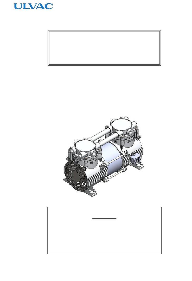
Ulvac DAP-6D Series User manual

Ulvac
Ulvac Desktop YTP User manual

Ulvac
Ulvac DIS-251 User manual

Ulvac
Ulvac UTM300B User manual

Ulvac
Ulvac UTM-MS Series User manual

Ulvac
Ulvac PBL Series User manual
Ulvac
Ulvac PMB-040C User manual