REMKO RVS Series Product guide

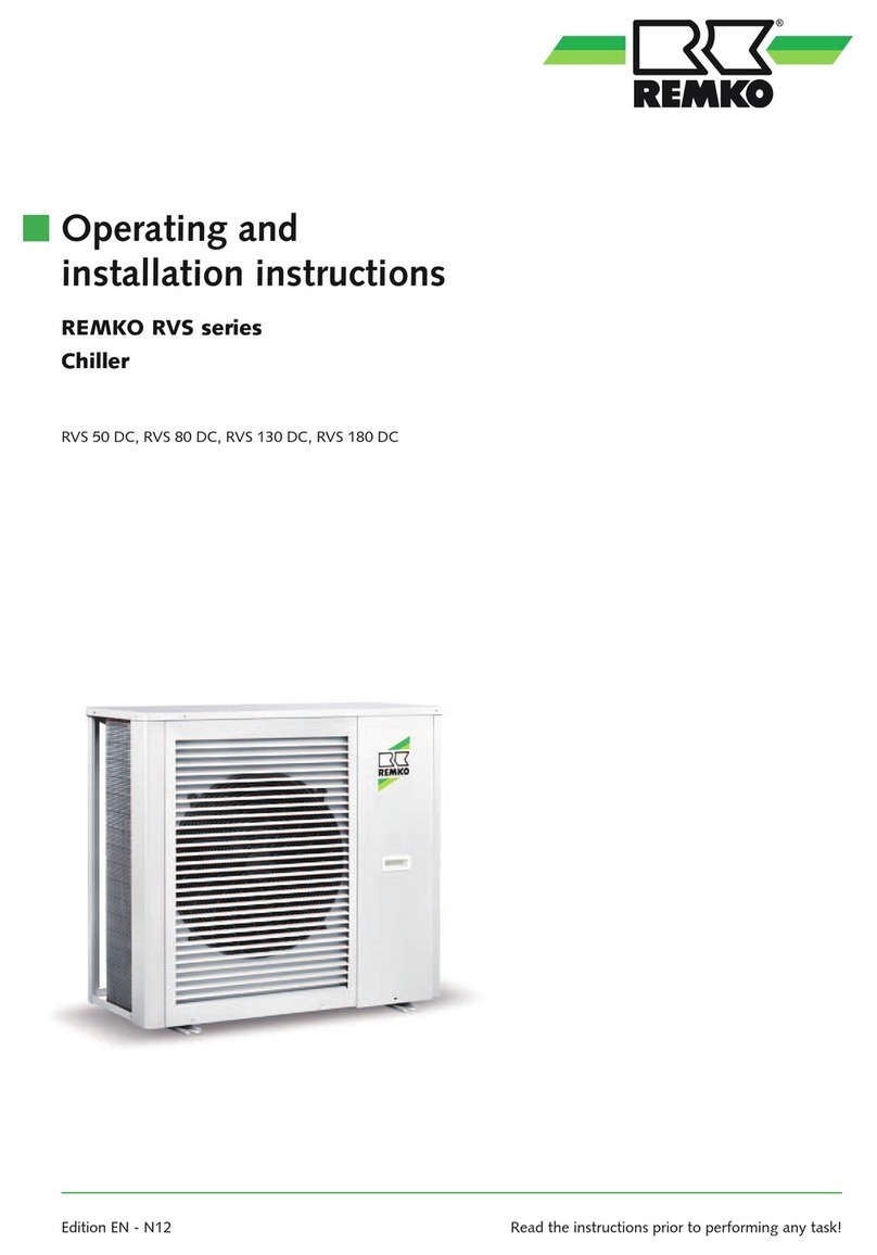
Operating and
installation instructions
Edition EN - Z05 Read the instructions prior to performing any task!
RVS 220 DC, RVS 260 DC
REMKO RVS series
Chiller


Content
Carefully read this operating manual prior to commissioning/using
the units!
This operating manual is a translation of the German original.
This manual is an integral part of the unit and must always be kept
inthe vicinity of the installation location or on the unit itself.
Subject to modifications. No liability accepted for errors or misprints!
Safety notes 4
Environmental protection and recycling 4
Guarantee 4
Transportation and packaging 5
Unit description 5
Intended use 5
Ecological design directive 5
Cooling cycle 6
Usable limits 7
Operation 8-19
Installation instructions for qualified personnel 20
Installation 21-26
Care and maintenance 27
Shutdown 27
Electrical wiring 28-29
Electrical drawings 30-31
Leak testing 32
Before commissioning 32-33
Commissioning 34
Overhaul and repair 35
Troubleshooting and customer service 36-38
Resistance table 39
Dimensions 40
Technical data 41
R410A
Refrigerant
3

Safety notes
Disposal of packaging
All products are packed for
transport in environmentally
friendly materials. Make a valuable
contribution to reducing waste
and sustaining raw materials. Only
dispose of packaging at approved
collection points.
Disposing of the units
and their components
Only recyclable materials are used
in the manufacture of the units
and components.
Help protect the environment
by ensuring that the units or
components (for example
batteries) are not disposed
of in household waste, but
only inaccordance with
local regulations and in an
environmentally safe manner,
e.g. using authorised disposal
andrecycling specialists orcouncil
collection points.
Environmental
protection and
recycling
Carefully read the operating
manual before placing the unit in
service for the first time. It contains
useful tips and notes as well as
hazard warnings to prevent injury
to persons or material damage .
Failure to follow the directions
in this Manual can endanger
persons, the environment and
theequipment itself and will void
any claims for liability.
■
Keep this manual and
therefrigerant data sheet near
the unit.
■ Only qualified personnel may
set up and install the units and
components.
■ The set-up, connection, and
operation of the unit and its
components must take place
inaccordance with theoperating
conditions stipulated in this
manual and comply with all
applicable local regulations.
■ Stationary units must be
permanently installed for
operation.
■ Modification of the units
and components supplied by
REMKO is not permitted and
can cause malfunctions.
■ Units and components may
not be operated in areas where
there is an increased risk of
damage. Observe the minimum
clearances.
■ The electrical power supply is to
be adapted to the requirements
of the units.
■ The operational safety of
the units and components
is only assured if they are
fully assembled and used as
intended. Safety devices may
not be modified or bypassed.
■ Do not operate units or
components if there are obvious
defects or signs of damage.
■ All housing parts and unit
openings, e.g. air inlets and
outlets, must be free from
foreign objects, liquids, or gases.
■ The units and components must
be kept at an adequate distance
from flammable, explosive,
combustible, abrasive and dirty
areas or atmospheres.
■ Contact with some parts
oftheunit or components can
result in burns or other injuries.
■ Installation, repair and
maintenance work may only
be carried out by authorised
specialists. Visual inspections
and cleaning can be performed
by the operator as long as
theunit is disconnected from
the power.
■ Take appropriate precautions
when performing installation,
repair or maintenance work or
cleaning the unit to make sure
the unit does not pose a danger
to persons.
■ The units and components
should not be exposed to any
mechanical load or extreme
levels of humidity.
Guarantee
In order to make warranty claims,
itis essential that the ordering party
or their representative complete
and return the “certificate of
warranty” and “commissioning
report” to REMKO GmbH & Co.
KG at the time when the unit was
purchased and commissioned.
Thewarranty conditions are
listed in the "General terms and
conditions". Furthermore, only
theparties to a contract can
conclude special agreements
beyond these conditions.
Inthiscase, contact your
contractual partner in the first
instance.
REMKO RVS SERIES
4

thesafety functions, is used to
control the cooling capacity.
Apotential-free contact provides
for remote enabling.
The unit is designed for outdoor
installation. Under certain
circumstances, it can also be used
in indoor areas.
The unit cooling cycle comprises an
evaporator, compressor, electronic
injection valve, condenser,
condenser fan, pressure transducer,
high and low pressure switches
and a 4-way changeover valve
for heating mode. The medium
cycle comprises a tube bundle heat
exchanger, a circulation pump and
a flow switch.
Vibration dampers, cabled remote
controls and glycol concentrate are
available as accessories.
The units are shipped in sturdy
transport packaging. Immediately
check the units on delivery and
make a note of any damage or
missing parts on the delivery note.
Inform the forwarding agent and
contractual partner.
Claims under guarantee made at
alater date will not be accepted.
Unit description
Transportation and packaging
In cooling mode, the unit (an
air-cooled chiller) takes heat out
of the operating medium to be
cooled, water or a mixture of
water and glycol, within a closed
medium cycle in the evaporator
(plate heat exchanger) and passes
it on to the closed cooling cycle.
As a consequence of the heat
exchange, the medium cools and
the refrigerant in the cooling cycle
vaporises under low pressure.
The gaseous refrigerant
enters an electric compressor
(scroll construction) which
increases thepressure and
thetemperature of the refrigerant.
The gaseous refrigerant is
led into a finned condenser,
which, as a consequence of
theheat exchange, condenses
the refrigerant under high
pressure to a liquid. The air
emerging at thecondenser heats
the environment. The liquid
refrigerant is fed by means of a
variable injector valve back to
the evaporator where the circuit
begins again.
A return temperature dependent,
seamless controller, which ensures
the unit's operation and all of
Intended use
Depending on the model and
theunit, the units are only
intended to be used as a chiller
for the cooling of the operating
medium water or a water-glycol
mixture within a closed medium
cycle.
Any other use or use in a way
thatexceeds the definition above
is considered non-intended
use. Themanufacturer/supplier
assumes no liability for damages
arising from non-intended use.
The user bears the sole risk in such
cases.
Intended use also includes working
in accordance with the operating
and installation instructions and
complying with the maintenance
requirements.
Applicability
Within the course of continuous
further development of all
products, REMKO GmbH & Co.
KG reserve the right to carry
out technical changes tothe
units as well as updates to
thedocumentation.
The documentation on the unit
(name plates, wiring diagrams,
etc.) shall be considered as part of
the overall documentation.
Ecological design directive
The regulation (EU) 2016/2281
(LOT 21) approved by
theEuropean Commission is
the enforcement action for
the ecological design directive
2009/125/EC, whose principal
objective is to reduce the primary
energy demand in the European
Union by 2030 and to reduce
theemissions of hazardous
substances associated with this.
The chillers from REMKO
comply with the applicable
energy requirements from
theecological design directive.
Theproduct datasheet required
per the ordinance, to verify
ERP conformity is attached as
aseparate document and is also
available for download from
www.remko.de.
Proper handling
Insofar as intervention is required
in the refrigerant circuit of theunit
during maintenance or repair
work, all work shall be carried
out exclusively by persons and
companies who have a certificate in
accordance with the prerequisites
of EC ordinance no. 517/2014 of
theEuropean Council.
5

Cooling cycle
1
2
3
4
5
6
7
8
9
2
2
2
7
Legend:
1 Compressor
2 Schrader valve
3 High-pressure switch
4 4-way changeover valve
5 Low-pressure switch
6 Tube bundle heat exchanger
7 Filter dryer
8 Electronic expansion valve
9 Finned condenser
Cooling cycle
REMKO RVS SERIES
6

Usable limits
RVS DC units are chillers with heat pump function. The primary purpose of the units here is cooling mode, whilst
the heating function represents an additional function by means of reverse circulation.
For trouble-free unit operation and compliance with the legal warranty conditions, it is essential that the unit
isbeused within its respective usable limits. These are shown in the following diagram. Further information
onthis can likewise be found in the technical data.
Usable limits
-5
0
5
10
15
20
25
Wassereintrittstemperatur
30
-20 -15 -10 -5 0 10 15 20 25 30 35
Umgebungstemperatur
25
30
35
40
45
50
55
Wassereintrittstemperatur
540 45 50
60
-25
-20 -15 -10 -5 0 10 15 20 25 30 35
Umgebungstemperatur
540 45 50
A
-30
B
-35 -25
-35 -30
65
A
Ambient temperature
Ambient temperature
Water inlet temperature Water inlet temperature
Legend
A Standard version
B Low-temperature version
7

Operation
Button symbol Designation Description
Mode key Operating modes can be changed, temperature settings changed and parameters set
by pressing the mode key
On/off key The system can be switched on and off with the On/Off key. In addition, it is also
possible to cancel the current operation and return to the previous operating stage.
Up arrow key Values can be adjusted and pages scrolled through with the up arrow key
Down arrow key Values can be adjusted and pages scrolled through with the down arrow key
Clock key The clock key is used to set up and execute timer functions
Display/control unit
The controller of the chiller is to be operated with the touch pad, which is located right on the unit in a
housing protected from splashed water. To open the housing, press the "PRESS" button on the right-hand side
ofthehousing. After operating the controller, close the housing again in order to prevent water ingress.
If there is no activity on the controller for longer than 60 seconds, the display switches to stand-by mode and
novalues are displayed. The display can be activated by touching any part of the display.
REMKO RVS SERIES
8

Button symbol Designation Description
Operating mode
Cooling Is displayed when the system is in cooling mode
Operating mode
Heating Is displayed when the system is in heating mode
Defrosting operation Appears during the defrosting procedure (only in heating mode)
Compressor Appears when the compressor is running
Circulation pump Appears when the circulation pump is running
Fan Appears when the fan is running
Timer Is displayed with the activation of a timer
Water outlet Appears when the digital display shows the water outlet temperature
Water inlet Appears when the digital display shows the water inlet temperature
Malfunction Is displayed if there is a fault present
Temperature (°C) Appears when the digital display shows the a temperature in °C
Temperature (°F) Appears when the digital display shows the a temperature in °F
Setting Is displayed if the value is set
Seconds Appears when the digital display shows seconds
Minutes Appears when the digital display shows minutes
Hours Appears when the digital display shows hours
Pressure Appears when the digital display shows a pressure
Medium flow rate Appears when the digital display shows a medium flow rate
9

Switching the unit on
The unit is switched on by pressing the key for 1 second.
A further 1 second press of the key in the start screen will switch the unit back off again. After one minute
without being used, the display darkens.
Setting the operating mode
To set the operating mode, press the key on the start screen for 1 second. The mode can thus be set to either
cooling or heating .
Setting the setpoint (return temperature)
To set the setpoint for the return temperature, briefly press the or key in the start screen. The display
flashes. Now the setpoint can be changed in steps of 0.5 with the same keys. Once the desired temperature is set,
confirm the input with the key. The value set will be saved and you are returned to the start screen.
If there is no activity for 20 seconds during the set-up process, the system automatically returns to the start screen
without changing any of the settings.
In order to cancel the adjustment process press the key to return to the start screen without changing any
ofthe values.
Before setting the operating mode, this must be implemented by installing/removing a wire jumper on
thecorresponding terminals (see chapter Electrical wiring).
REMKO RVS SERIES
10

Setting the time
To set the system time, briefly press the and keys simultaneously.
The key appears on the right-hand side of the screen. Press this briefly and the display for the hours starts
toflash. The hours can now be adjusted with the and keys.
Confirm the hours with the key and the minute display starts to flash.
The minutes can now be adjusted with the and keys.
Confirm again by briefly pressing the key. The settings are saved and you are returned to the start screen.
If there is no activity for 20 seconds during the set-up process, the system automatically returns to the start screen
without changing any of the settings.
In order to cancel the adjustment process, press the key to return to the start screen without changing any
ofthe values.
11

Saving timer programs
To save a timer program, briefly press the and keys simultaneously.
The key appears on the right-hand side of the screen.
Press this for 2 seconds.
Now you can select a switch-on or switch-off point with the and keys.
ON 1 = Switch-on point for the first timer program
OFF 1 = Switch-off point for the first timer program
ON 2 = Switch-on point for the second timer program
OFF 2 = Switch-off point for the second timer program
Use the key to confirm your selection. The display for the hours starts to flash.
The hours can now be adjusted with the and keys.
Confirm the hours with the key and the minute display starts to flash. The minutes can now be adjusted
withthe and keys.
Confirm again by briefly pressing the key and the settings are saved.
To exit the timer menu, press the key briefly
In order to cancel the adjustment process press the key to return to the start screen without changing any
ofthe values.
REMKO RVS SERIES
12

If the system is deactivated and the time set for a switch-on point (ON1, ON2) is reached, the system activates
autonomously. It then carries out the operation with the settings before deactivating again.
If the system is activated and the time set for a switch-off point (OFF1, OFF2) is reached, the system de-activates
autonomously.
13

Deleting timer programs
To delete a timer program, briefly press the and keys simultaneously.
The key appears on the right-hand side of the screen. Press this for 2 seconds.
Now you can select a switch-on or switch-off point that you wish to delete with the and keys.
ON 1 = Switch-on point for the first timer program
OFF 1 = Switch-off point for the first timer program
ON 2 = Switch-on point for the second timer program
OFF 2 = Switch-off point for the second timer program
Use the key to confirm your selection. The display for the hours starts to flash.
The switch-on or switch-off point can now be deleted with a brief press of the key.
If the switch-on or switch-off point has been successfully deleted, the display shows - - : - - .
To return to the start screen, press the key briefly.
REMKO RVS SERIES
14

Malfunction indication
If a fault arises on the unit, the controller reports this automatically. The screen shifts to the fault display and
displays a fault code. The meanings of the various codes are listed in the Faults and fault causes chapter.
If multiple faults arise at the same time it is possible to switch between the fault displays with the and
keys.
You can return to the start screen by briefly pressing the key.
If there is no activity for 10 seconds, the display automatically returns to the fault display.
If the fault is rectified, the controller will detect this and the fault display will disappear automatically.
If a major fault arises 3 times within a 30 minute period, the fault message must
be manually reset after the cause of the fault has been successfully removed.
A listing and definition of the major faults can be found in the Faults and fault causes chapter.
Once the cause of the fault has been removed the fault message must be manually reset by pressing the key
for 2 seconds.
15

Calling up operating parameters
To display the operating parameters, briefly press the key on the start screen. Now the probe values and other
operating conditions can be called up here. The and keys can be used to navigate between the different
operating parameters.
The meaning of the individual parameters can be found in the list below.
ID Designation
O Device component status
O01 Compressor status
O03 Fan high stage status
O04 Fan low stage status
O05 Circulation pump status
O07 4-way changeover valve status
O08 Not used
O09 Not used
O11 Alarm status
O12 Crankcase heating status
O13 Condensate drain heating status
O15 Injection valve position
O17 EVI valve position
O124 No function
ID Designation
S Switching statuses
S01
High-pressure switch switching status
S02
Low-pressure switch switching status
S03 Flow switch switching status
S04 internal
S05 External enabling switching status
S06 internal
S10 internal
Kurz
Kurz
Kurz
Kurz
Short Short
Short
Short
REMKO RVS SERIES
16

Defrosting operation
In heating mode, condensate forms on the finned heat exchanger and this can freeze under certain conditions
and thus have an insulating effect. Because this can significantly impair the operation of the unit, the system
can switch to defrosting mode if required. The symbol for defrosting is shown on the system display during
thedefrosting process. Once the defrosting process has ended, the symbol disappears and the system carries on
with normal operation.
ID Designation
T Probes
T01 Medium inlet temperature
T02 Medium outlet temperature
T03 Matrix temperature
T04 Ambient temperature
T05 Suction gas temperature
T06 Anti-freeze temperature
T09 internal
T10 EVI inlet temperature
T11 EVI outlet temperature
T12 Final compression temperature
T27 Fan 1 speed
T30 Fan 2 speed
T31 Compressor setpoint frequency
T32 Compressor actual frequency
T33 IPM safety temperature
T34 AC input voltage
T35 AC input current
T36 Compressor current
consumption (phases)
T37 Internal DC control voltage
T38 IPM temperature
17

Anti-freeze protection
The anti-freeze protection is based primarily on 2 parameters:
ID Designation Factory setting
A04 Anti-freeze temperature 4 °C
A05 Anti-freeze protection temperature difference 3 °C
Cooling mode:
If the water outlet temperature (T02) is less than or equal to the anti-freeze protection temperature (T06),
thesystem switches to anti-freeze protection.
Heating mode:
If the water outlet temperature (T02) is less than the water inlet temperature (T01) or less than the anti-freeze
protection temperature (T06), the system switches to anti-freeze protection.
In both cases, the system only carries on with normal operation once the water outlet temperature rises by
theanti-freeze protection temperature difference.
The anti-freeze temperature is set to +4 °C at the factory.
If glycol is used, it is possible to change the parameters to operate at lower temperatures, depending on the glycol
concentration. The table below can be helpful for this.
Adjustment is only possible after password input. For this purpose, please contact REMKO.
During use and
disposal the product and
safety data sheets of the glycol
type which is used must be
observed.
Glycol
content
Frost
protection
+-2°C
Correction factors when using a
mixture of glycol* and water
Cooling
output
Power
consumption
Medium
flow rate Pressure loss
Vol. % °C KLKPE KVKD
0 0 1 1 1 1
20 -9 0.960 0.995 1.040 1.19
35 -21 0.950 0.990 1.090 1.35
40 -26 0.925 0.985 1.105 1.51
Use the required type and
mix ratio appropriate for
theapplication area to ensure
the freezing point.
* We recommend using an ethylene glycol mixture. Observe the safety and
product data sheets for the glycol type being used.
!CAUTION
!CAUTION
REMKO RVS SERIES
18

Setting the anti-freeze protection parameters
Press the key on the start screen briefly to access the operating parameters level.
Then press the key in the operating parameters level for 3 seconds to access the next level down. A password
input will be required for this. Now enter the password with the and keys and confirm with the key.
With the arrow keys / you can now navigate to the parameter section “A”. To open this section,
press the key once. Using the arrow keys / the corresponding parameters can be selected. Once
thecorresponding parameter has been selected, press the key once so that “SET” starts flashing on
thedisplay. Using the arrow keys / the value can now be changed accordingly. After changing the value,
thismust beacknowledged with the key.
Kurz
3 Sek.Kurz
Kurz
Kurz Kurz
SET
Kurz
Kurz
Kurz
Short 3 sec.
Short
Short
Short
Short
Short
Short
Short
19

Installation instructions for qualified personnel
■
Observe the manuals for
theindoor units and chillers
when installing the entire
system.
■
The indoor units and
chillers work independently.
Aconnecting line between
thetwo is not necessary.
■
Select an installation location
which allows air to flow freely
through the air inlet and
outlet See section "Minimum
clearances".
■
Do not install the unit in
theimmediate vicinity of
devices which generate
intensive thermal radiation.
Installation in the vicinity
ofthermal radiation reduces
theunit output.
■
Lift the unit only at intended
lifting points. Never apply loads
to the medium piping.
■
The medium connection lines,
valves and connections must be
insulated impervious to vapour
diffusion.
■
Seal off open lines to prevent
dirt getting in.
■
Make all electrical connections
in accordance with applicable
DIN and VDE standards.
■
Always ensure the electrical
cables are properly connected
to the terminals.
Otherwise there is a risk of fire.
■
Comply with all regulations
governing structural and
building requirements and
conditions with regard to
theinstallation site.
■
In the selection of the
installation site, pay attention
to the site itself and to any
possible acoustic reflection from
surrounding units.
■
To avoid the transmission of
vibrations to the installation
site, the units must be installed
on vibration absorbing material
or on vibration decoupled
foundations.
In doing so, make sure that
the lines are also vibration
decoupled.
■
If the installation site must
fulfil special sound emission
requirements, these must
be realised on-site when
appropriate adjustments can be
made.
In these cases, please consult an
appropriate acoustics expert.
■
The units are tested in
thefactory and require
only electrical and hydraulic
installation by a suitable
specialist.
Important notes prior
toinstallation
■
The unit must be kept upright
when transporting to a higher
elevation:
■
Check the contents of the
packaging for completeness
and check the unit for visible
transport damage.
Report any damage
immediately to your contractual
partner and the shipping
company.
■
If necessary, also insulate
the condensate drainage line
(only units with HP-function).
In dual systems with cooling
and heating modes, the
requirements of the current
Energy-Savings-Ordinance
(EnEV) are to be complied with.
Transport
■
Transport the unit in its original
packaging as close as possible
to the installation location. You
avoid transport damage by do-
ing so.
■
The units may only be moved
as installed (upright) using
appropriate transport gear
(Figure 1).
Secure against tipping!
1 Standing transport
REMKO RVS SERIES
20
Other manuals for RVS Series
1
This manual suits for next models
2
Table of contents
Other REMKO Chiller manuals
Popular Chiller manuals by other brands

Weber
Weber Refrigerator owner's guide

Daikin
Daikin REYQ-AATJA Service manual

BICOLD
BICOLD WBA Series User instructions

Carrier
Carrier MINIMUM LOAD CONTROL ACCESSORY 30XA080-500 Controls, start-up, operation, service and troubleshooting instructions

Samsung
Samsung DVM Chiller Training

Arctica
Arctica HEF967 Installation, operation & maintenance manual