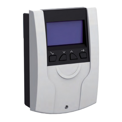
REMKO ATR 10 User manual

Operating and
installation instructions
Edition GB - N12 Read the instructions prior to performing any task!
ATR 10
REMKO ATR
Electronic temperature regulation


3
Contents
Environmental protection and recycling 4
Safety notes 4
Controls 5
Function description 5-7
Clock 8
Time program 8-9
Control parameters 10
Default settings 10-11
Setting overview 12
Assembly 13
Installation 14
Customer data 15
Circuit diagram 16-18
Technical data 19
Carefully read this Installation manual prior to commis-
sioning/using the units!
This operating manual is a translation of the German original.
This manual is an integral part of the unit and must
always be kept in the vicinity of the installation location
or on the unit itself.
Subject to modifications; no liability accepted for errors
or misprints!

4
REMKO ATR
Carefully read the operating manual
before placing the unit in service
for the first time.
It provides useful tips and notes
as well as hazard warnings to prevent
injury and material damage .
Failure to follow the directions in
this manual can endanger the equipment
itself and will void any claims for liability.
This electronic temperature controller
provides room temperature-dependent
regulation of heating and ventilation
units or zone valves in enclosed spaces.
■
Keep this manual close to
the equipment
■ Only qualified authorised personnel
may assemble and install the units
and components.
■ The units must be set up, connected
and operated in accordance with
the manual and the generally
applicable regulations, including
any regional regulations
■ Modification of the units and
components supplied by REMKO
is not permitted and can cause
malfunctions
■ Units may not be used in areas where
there is an increased risk of damage.
Safety notes
Environmental protection
and recycling
Disposal of packaging
All products are packed for transport
in environmentally friendly materials.
You can make a valuable contribution
to reducing waste and to sustaining raw
materials by only disposing of packaging
at approved collection points.
Disposal of old equipment
At the end their service lives, the
units must not to be disposed of in
household waste. They must be taken
to a special collection point for electrical
and electronic units.
CAUTION
Copyright
The redistribution, even in part,
or the use of this documentation
for purposes other than intended
is strictly prohibited without
the written authorisation of
REMKO GmbH & Co. KG
is prohibited.

5
Function description
The weekly timer controls the daytime
and nighttime temperatures in hourly
operation. The three keys ¹☾
are used to select the operating mode.
Controls
4 = Reset key (ATR-10 board)
5 = Operating status indicators
6 = Operating mode indicators (H/L)
1 =
Daytime temperature adjustment button
2 =
Nighttime temperature adjustment button
3 = Program keys
4 1
2
356
The selected operating mode is displayed
on the right-hand side of the display
with the indicators [5]. In hourly
operation, a second indicator is used
to display the respective temperature
level.
In "Off" operating mode, no indicator
is displayed.
Display in hourly operation, daytime operation
s
s
s
MO DI MI DO FR
SA SO
Switch on
The controller is switched on with
the daytime () or nighttime operation
key (☾) or by switching on hourly
operation (¹), provided that this
has already been programmed.
The Ventilation operating mode (
) is
switched on by simultaneously pressing
the and ☾keys. When ventilation
is active, ventilation is provided in
daytime operation and switched
off during nighttime operation.
Display in "Off
" operating mode
MO DI
MI DO
FR
SA
SO

6
REMKO ATR
MO DI
MI DO
FR
SA
SO
MO DI
MI DO
FR
SA
SO
Nighttime temperature
The nighttime temperature is adjusted
with the lower adjustment button [2].
The nighttime temperature
is independent of the daytime
temperature. The nighttime temperature
is adjusted between -5°C and
+25°C with the adjustment button
[2]. The absolute value is displayed
in the right-hand half of the display.
The unit displays the actual temperature
again automatically three seconds after
the last rotation of the button.
The current setpoint can be requested
by pressing the SET program key.
The actual temperature is displayed
again automatically after three seconds.
Off
The controller is switched
off by simultaneously pressing the ¹
and program keys.
The operating mode is no longer
displayed on the right-hand side
of the display. The unit continues
to record the actual temperature,
however the switch relay for
temperature regulation is no longer
activated.
Frost protection is no longer available.
Depending on the selected units,
"Heating or Ventilation", and additional
relay out is activated for signalisation.
Display with switched "Heat" output
Display with switched "Ventilate" output
The "Heat/Ventilate" functions are
switched only with the specified key
combination.
In "Heat" mode, the activated relay
is displayed on the left-hand side
of the display with an upwards pointing
arrow, in "Ventilate" mode, with
a downwards pointing arrow.
s
s
s
CAUTION
There is no frost protection
for excessively low overnight
temperatures.
Daytime temperature (daytime operation)
The desired temperature (+5 to +40°C)
is adjusted with the upper adjustment
button [1]. This is displayed in the right-
hand half of the display in place
of the actual temperature.
The unit displays the actual temperature
again automatically three seconds after
the last rotation of the button.

7
Hand key
The key is used to modify the current
temperature level in hourly operation.
The selected temperature level
is displayed on the right-hand side
of the display with the indicators.
This function is deleted with the next
program point.
Reset key
Three different reset options are
available:
1. Start-up reset:
The R [4] key allows the unit to be
started up again in the event of a failure
due to a malfunction.
The program and parameter settings are
retained.
The clock will need to be set again.
2. Global reset:
In order to force the unit to start
up with factory settings, the –and
PROG keys in addition to R[4] must
be pressed.
After releasing the Rkey, the –and
PROG keys must continue to be pressed
until the version number (Id:02...)
appears on the display.
3.
Malfunction RESET (acknowledgement)
In the event of a malfunction (open
contact at external input), the –and
PROG (RESET) key combination
can be used to force a malfunction
acknowledgement of the relay.
The relay is activated for as long
as the key combination is pressed.
Any previously entered individual
time program and parameter
settings will be lost.
NOTE
Malfunction code
In the event of a (heating unit)
malfunction (contact opened)
at an external input, "StoErng"
is displayed on the control unit.
In this status, the controller cannot
be operated, however the control unit
continues to function normally.
The special "RESET" key combination with
the –and PROG keys allows a malfunction
to be acknowledged and reset. If this
key combination is pressed for longer
than 5 seconds, the "flashing code"
from the heating unit on the display can
be read off. Each flashing pulse from
the heating unit results in the malfunction
text being hidden for a brief moment.
In the event that multiple units are
involved in a malfunction shutdown,
it is likely that the flashing codes of
the individual units will overlap. In this
case, each unit must be checked separately
for the respective malfunction.
If multiple units are connected to
the ATR-10 and multiple units have
a malfunction, it is highly likely
that the flashing codes will overlap.
NOTE

8
REMKO ATR
The +and –keys can be used to modify
the respective flashing value (P01 - P16).
The SET key takes you to the next
setting (Program point number -> Time
-> Days of week -> Temperature level).
Pressing the SET key takes you
to the time setting.
The clock is a weekly timer with approx.
4 hours of power reserve.
On initial commissioning or following
a reset, a flashing zero appears
on the display.
The time can be set by pressing the ¹
key for 3 seconds or following a restart
after a reset.
The flashing values can be modified with
the + and – keys.
The SET key takes you to the next
setting (Hours -> Minutes -> Year ->
Month -> Day).
After confirming the minutes with
the SET key, the clock is started with to-
the-second accuracy.
After confirming the day, the unit returns
to the operating mode from which
the "Set time" menu was called.
MO DI
MI DO
FR
SA
SO
MO DI
MI DO
FR
SA
SO
The time program can be modified
by briefly pressing the PROG key.
16 program spaces are available.
These allow up to 112 switching times
to be programmed.
The program point number
P01-P16 appears on the display,
the corresponding time and day of
the week at/on which the corresponding
temperature level becomes effective.
The temperature level that is active
on the various day is displayed
on the right with the indicators.
Pressing the +and –keys modifies
the switching time point of the clock
in 10 minute increments.
The clock changes automatically
between summer/winter time.
NOTE
Clock Time program
MO DI
MI DO
FR
SA
SO

9
The following standard program
is factory pre-set
P01 MO-SU
from 06:00 Daytime temp.
P02 MO-FR
from 22:00
Nighttime temp.
P03 SA-SO
from 23:00
Nighttime temp.
Pressing the SET key opens the settings
for the days of the week (flashing day
indicators).
The following selection options are
available:
MO - SU / MO - SA / MO - FR / SA -
SU, or each individual day of the week.
The selections are madeby pressing
the +and –keys.
Pressing the SET key again opens
the settings for the desired temperature
values (flashing indicators in front
of the respective temperature level).
Pressing the +and –keys modifies
the temperature level.
The desired temperature settings for
daytime and nighttime are confirmed
with the adjustment buttons [1 and 2].
After pressing the PROG key with
flashing program point number, the unit
returns to the operating mode from
which the "Modify time program" was
called.
Ineffective program points are marked
with ––:–– instead of the time.
Display Key Explanations
1. PROG Set time program (modify)
2. 22:00 P01 +/- Program selection P01 flashes; modify setting with [+]
3. 22:00 P02 SET Complete entry
4. 22:00 +/- Time setting flashes; modify setting with [-]
5. 18:30 SET Complete entry
6. ╹╹╹╹╹ +/- Days of week flash; modify setting with [+]
7. ╹╹╹╹╹ SET Complete entry
8. ☾SET Arrow flashes next to nighttime operation; retain setting
9. P02 PROG P02 flashes; programming end with (PROG)
Programming example:
Change of P02 to: MO - SA, from 18:30; nighttime operation; (P02)
MO DI
MI DO
FR
SA
SO

10
REMKO ATR
MO DI
MI DO
FR
SA
SO
Default settings
Values or functions can be modified with
the +and –keys.
The SET key moves to the next selection.
Confirming the last function with
the SET key returns the unit to
the operating mode from which
the "Set basic functions" menu
was called.
The individual functions have
the following meanings:
Pressing the PROG key for 6 seconds
opens a menu in which the different
basic functions can be set.
The function is displayed in the left-hand
half of the display and the corresponding
value or status in the right-hand half
of the display.
Pressing the PROG key for 3 seconds
opens a menu in which the different
regulation parameters can be set.
The parameter is displayed in the left-
hand half of the display and
the corresponding value or status
in the right-hand half of the display.
The value can be modified with the +
and –keys.
The SET key moves to the next
parameter.
Confirming the last parameter
with the SET key returns the unit
to the operating mode from which
the "Setparameters" menu was called.
The individual parameters have
the following meanings:
Parameter Fact. Min. Max.
SwitchingdiFFerence
±0.5 K ±0.1 K ±3.0 K
Control parameters
NOTE
In the event that a temperature
probe is faulty or missing, "FA IL"
appears on the display.
MO DI
MI DO
FR
SA
SO

11
Sensor calibration
SEnS (sensor calibration display)
Stabilised temperature values must
be available for sensor calibration.
In addition, sensor calibration must be
performed at a usual room temperature
of approx. 20°C.
In order to perform correct
temperature calibration, the actual
temperature displayed on the unit and
the temperature at the sensor (to be
measured with a suitable temperature
measuring instrument) must be known.
The difference between these two values
can be set within ±3.0 K limits under
the SEnS menu item.
Example:
20.7°C is shown on the unit display.
The temperature measuring instrument
shows 19.9°C as the temperature
at the sensor.
– 0.8 must therefore be set under
the SEnS menu item.
Pre-setting Limit
0.0 K ±3.0 K
NOTE
The accuracy of temperature
recording is dependent on the length
and cross-section of the lines
(see table on page 15).
MO DI
MI DO
FR
SA
SO
Key lock
Loc (key lock)
Key lock prevents the daytime and
nighttime temperatures from being
modified with the rotary buttons.
After removing the key lock, an
interim modified daytime or nighttime
temperature is adopted. The key lock
is deactivated by pressing the PROG key
for 6 seconds.
Active key lock is indicated by the key
symbol.
Pre-setting Alternatives
oFF
(inactive)
on
(active)
MO DI MI DO FR
SA SO

12
REMKO ATR
Default screen Nighttime
temperature
Time program
"diFF" control
parameter
"SEns" default
setting "Loc" key lock
Set time
program
SET
SET
SET
SET
SET
PROG
1 sec.
PROG
3 sec.
PROG
6 sec.
PROG
SET
SET
Set time
¹3 sec.
SET
Setting overview

13
Assembly
The electronic temperature controller
is suitable for wall mounting with
a surface-mounted cable inlet.
The external temperature probe
must, where possible, be fitted
to an internal wall around 1.5 m
above the floor.
NOTE The external temperature probe
must be installed such that
it can record the average room
temperature. Draught and proximity
to windows, doors and heat
sources, etc. must be avoided.
NOTE
Probe not fitted immediately next to
windows!
Probe not fitted directly next to hot air
flow!
We reserve the right to modify the dimensions and design as part of the ongoing technical development process.
194
165
104
94
160
75,5 75,5
15120
Housing dimensions

14
REMKO ATR
Installation
Maximum line
length Line cross section
10 m 1.50 mm²
15 m 1.50 mm²
20 m 2.00 mm²
■
De-energise all live lines before
working on the unit
■
Connections must be made
in accordance with the circuit diagram
on page 16,17 and 18
■
The unit is only approved
for connection to fixed lines
■
When installing the unit, it must
be ensured that lines carrying mains
electricity, such as the mains supply
and relay connection lines, cannot
come into contact with low-voltage
lines such as probe lines (minimum
clearance 4 mm for lines with basic
insulation)
■
The requirements of EN 60730
Part 1 must be adhered to to
ensure adequate protection against
connecting conductors self-loosening.
This may be achieved by securing
thelines with suitable cable ties
■
VDE 0100, EN 60730 Part 1
and the regulations of the local EVU
must also be observed
■
In the event that the unit does not
function as expected, begin by
verifying that it is correctly connected
and that there is a power supply
■
Use probe lines in accordance
with the requirements and note
the maximum line lengths and
requisite minimum cross sections
Errors on connection can cause
damage to the unit! No liability
will be assumed for damage caused
by incorrect connection and/or
improper operation!
CAUTION
CAUTION
For the avoidance of malfunctions,
the external probe lines must not
be routed together with other live
lines. Observe a minimum clearance
of 4 mm when using conductors
with basic insulation.
One RP-20 must be provided for each
unit in the event of group operation
of the GPS units. On-site junction
boxes must also be provided.
NOTE
For line lengths greater than 5 m, an
RP-20 should be provided a short
distance from the GPS device.
NOTE
CAUTION
In the event that the GPS unit is
operated in a group, a voltage of 230 V
AC will be present at the RP-20
fault message contact. As such,
the controller must be switched
off and disconnected from the mains
before opening the GPS unit or RP-20.
!

15
Customer data
Program point Start time Day(s) Temperature level
P01
P02
P03
P04
P05
P06
P07
P08
P09
P10
P11
P12
P13
P14
P15
P16
The following tables have been compiled for entering the individual customer data:
Time program:
We reserve the right to modify the dimensions and design as part of the ongoing technical development process.
Control parameters:
Switching difference
Functions:
Sensor calibration

16
REMKO ATR
We reserve the right to modify the dimensions and design as part of the ongoing technical development process.
Circuit diagram
Terminals P1 and S1 are
used for connection for fault
acknowledgement.
NOTE
A mains voltage must be permanently
available at terminals L and N
for the unit to function!
CAUTION
T2 P1 Ö1S1
PE LN
Heat/
Ventilate
release
Heat/
Ventilate
selection
P2 Ö2S2 P3 Ö3S3 N LPE
Fault
acknowledgement
External
sensor
Fault message
contact
AC
DC
A2A1
Selection switch
for fault message
contact
NC NO
CAUTION
The ATR-10 must not be
operated under 0°C. Ensure that
the installation location is frost-free.

17
Circuit diagram for one GPS unit
36
3534333231
T2 P1 S1 Ö1 P2 S2 Ö2 P3 S3 Ö3 NPE L
ATR-10
N
PE
L
A1 A2
Wahlschalter
auf NC stellen
NC NO
1
2
34
5
6
12
3 4
563
Set selection
switch to NC
GPS board
1. GPS
Temperature probe

18
REMKO ATR
Circuit diagram for GPS group operation
A1 A2 T2 P1 S1 Ö1 P2 Ö2 P3S2 S3 Ö3 N PE L
NC NO
Wahlschalter
auf NO stellenauf NO stellen
S3
S2
S1
A2
N
PE
31
32
33
34
35
36
X1 X2
PE
12
A1 A2 A1 A2 A1 A211 14 12
12 14 11 12 14 11 12 14 11A2 A1
R2 R3 R4R1
31 32 33 34 35 36
S3
S2
S1
A2
N
PE
31
32
33
34
35
36
X1 X2
PE
12
A1 A2 A1 A2 A1 A211 14 12
12 14 11 12 14 11 12 14 11A2 A1
R2 R3 R4R1
31 32 33 34 35 36
GPS Platine
Erste bis zur vorletzten RP-20
Netz 230V
GPS Platine
ATR-10
Letzte RP-20
5PEx1mm²
6PEx1mm²
5PEx1mm²
6PEx1mm²
ATR-10
Last RP-20
GPS board
Power supply 230V
GPS board
1 to penultimate RP-20
Set selection
swich to NO

19
Type ATR-10
Daytime temperature + 5 to + 40°C
Nighttime temperature - 5 to +25°C
Temperature probe KTY (external)
Probe tolerance ±1 K
Switching difference ±0.1 to ±3.0 K, adjustable
Temperature resolution Setpoint 0.5 K/actual value 0.1 K
Setpoint temperature setting Rotary buttons, menu
Program points 16
Timer switch Electronic weekly timer
Power reserve 1) approx. 4 hours
Display LCD display
Operating voltage 230 V/50 Hz
Power consumption approx. 2 VA
Relay contact 3 potential-free changers
Input contact 1
Max. permissible "load relay" switching current
10(4) A, 230 V AC
Max. permissible "signal relay" switching current
4 (2) A, 230 V AC, the minimum
switching current of 10 mA must be met
Electrical service life 0.5 x 10⁵ switching cycles
Max. permissible ambient temperature 0 to +50°C
Housing: Material ABS plastic
Enclosure class IP 54
Protection class II in acc. with DIN EN 60730-1
Dimensions W x H x D 194 x 160 x 104 mm
Fastening Surface-mounted wall installation
Weight approx. 750 g
EDP no. 1011373
Technical data
1) The power reserve is for the time only.
All other parameters are permanently saved.
We reserve the right to modify the dimensions and design as part of the ongoing technical development process.

REMKO INTERNATIONAL
... and also right in your neighbourhood!
Take advantage of our experience and advice
REMKO GmbH & Co. KG
Air conditioning and heating technology
Im Seelenkamp 12 D-32791 Lage
Postfach 1827 D-32777 Lage
Telephone +49 5232 606-0
Fax +49 5232 606-260
E-mail [email protected]
Website www.remko.de
We reserve the right to make technical changes and provide no warranty as to the accuracy of this data!
Table of contents
Other REMKO Controllers manuals
Popular Controllers manuals by other brands

PI
PI E-727 user manual

halstrup-walcher
halstrup-walcher PSD4 Series instruction manual

Panasonic
Panasonic EYFRZ01 operating instructions

Epever
Epever TRACER 6420 quick start guide

ABB
ABB PSTX30 370 Series installation instructions

fluidra
fluidra Astral Pool SLX Light Connect Lite installation instructions