ATTENTION
You need to use DF U mode to recover firmware for F4 Flight controller, and need a software tool called Zadig to replace the driver for you F.C
when you flash firmware at the first time.
Zadig 2.3.701
List All Device s
Ignore Hubs or Compos ite Parents
Create a Catalog File
Sign Catalog&Install Au to ge ner ate d cer tifi cat e
Advanced Mode
Log Verbosity
6. Start the “Betaflig ht ” configurator on the PC ;
7. Press and hold the “B OOT” on the FC , connec t the FC to the P C, then the F C is conne cted in the “D F U” mod e, then you can flash the firmw are;
8.For the firmware flashi ng , you can choose to load th e firmware online or local(L oc al is recommended, it
needs to download in adva nce in Betaflight websit e)
1.Start the Zadig softw are tool;
2.Press and hold the “B OOT” on the FC , connec t the FC to the P C.
3.Click “Options”,and s elect “List All Device s”.
4.Then select “S TM3 2 BOOT LOAD E R”,The n click “Replace Driver ”
5. Close the Zadig softwar e tool when replace succe ssfully,
Then disconne ct the F C from the PC.
ATTENTION
(Notice:If you've run the a bove steps before, then y ou don't need to repeat, st arting directly fro m the 6th step)
CONF IGURATOR 3.2.2
● Please don't flash any other firmware for FC except “OMNIBUSF4”.
● does not need to set the port.PPM receiver
SBUS or PEKTRUM receiver needs to turn on the “Serial RX” of ●
UART1 port.
is any deviation between the detected voltage/current with actual ●If there
situation, you can adjust the Scale value in the Betaflight-Power&Battery
● 3.3V ,5Vsupply is for low-current use only(3.3V 0.1A MAX, 5V 1A MAX).
●Please contact Flycolor sales or technical support for more information.
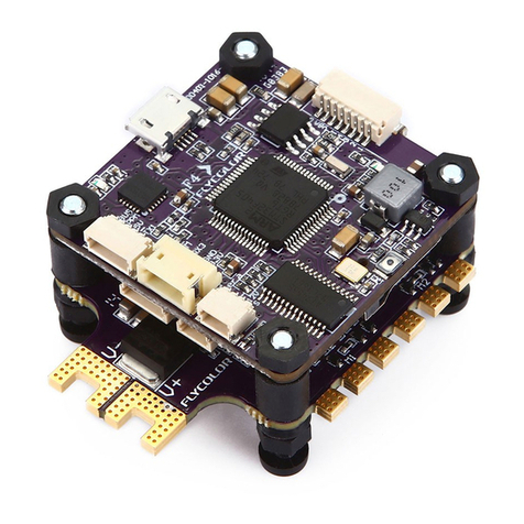
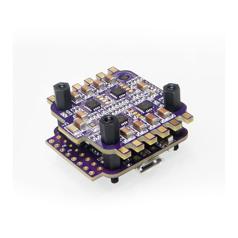
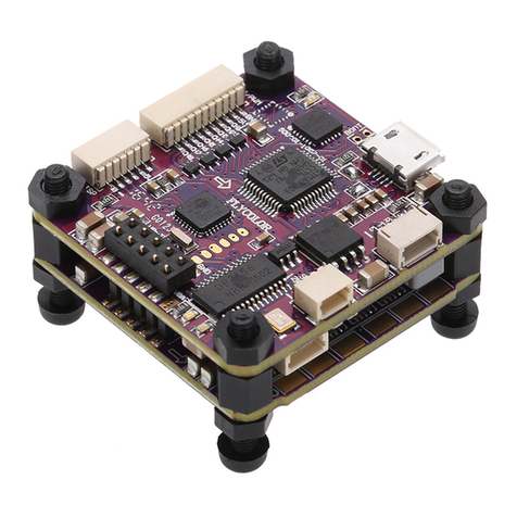
Raptor S-Tower F4-20A
05 Flash firmware for F C
06 More information
www.flycolor.net
ATTENTION
Thank you for using our product . Any Improper operation may cause personal injury damage to the product and related equipments. This high
power system for RC model can be dangerous ,we strongly recommend reading the user manual carefully and completely. We will not assume any
responsibility for any losses caused by unauthorized modifications to our product. We have the right to change the design, appearance,
performance and usage requirements of the product without notice.
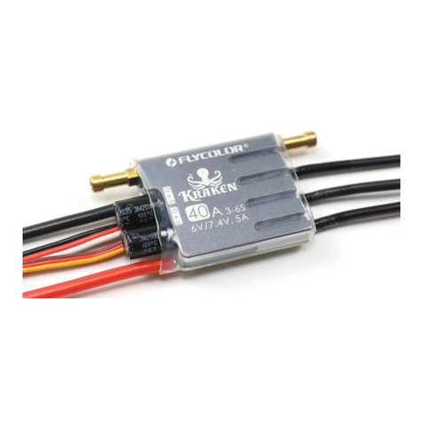
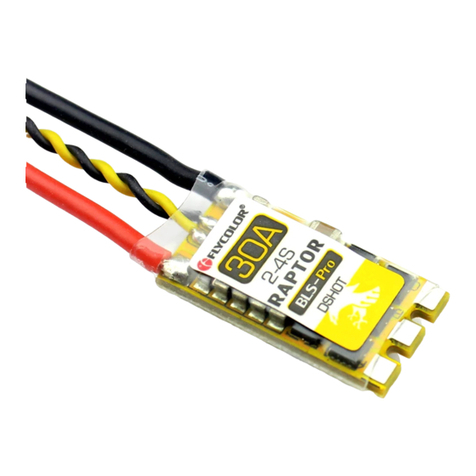
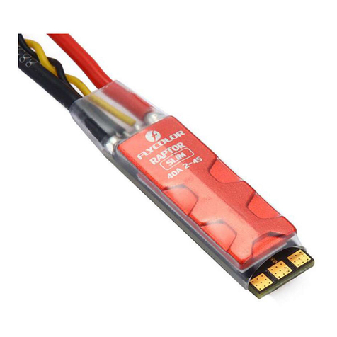
ESC
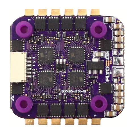
● EFM8 BB21F16G M C U, pipelined 8-bit C8051 core with 50 MHz maximum operating frequency.
ESC maximum speed is limited to 500k eR P M.● Dedicated 3in1 drivers, makes the start more smooth.
● ESC firmware: BLH eli-S,F-H-40.
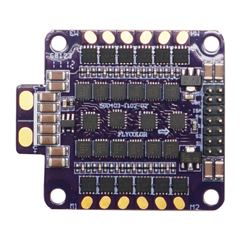
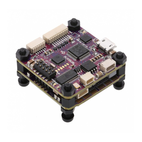
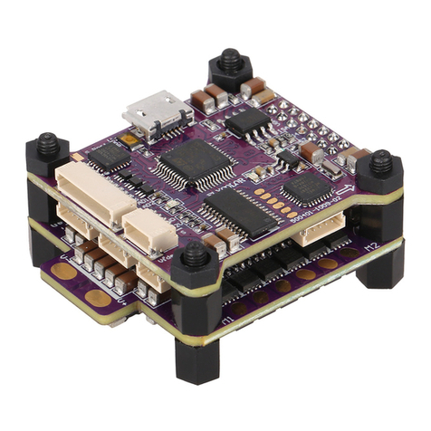
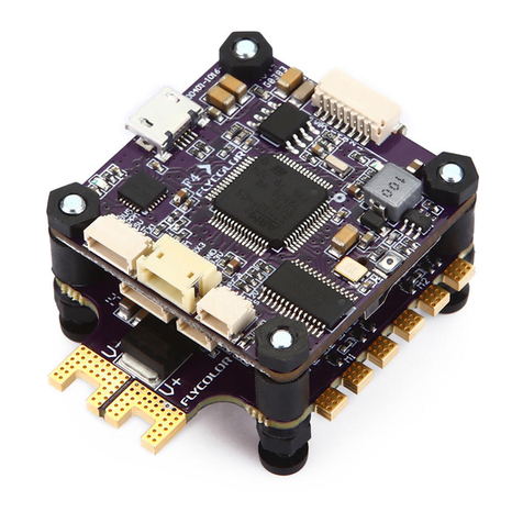
● Two layers tower structure between 4in1 ESC and FC, usi ng cable for quick connection, silicon sp acer for
supporting could reduce the effect of vibration on Flight C ontroller, makes the flight more stable.
BLHeli-S firmware. It is designed for superior performance in multirotors, and uses hardware generated motor ●
pwm for sm ooth throttle response and silent operation.
● The code supports regular 1-2ms pulse width input, as well as Oneshot125 , Oneshot42 and Multishot .
● Supports Dshot150, Dshot300 and Dshot600.Dshot is digital signal, anti-interference ability is stronger, and do
not need throttle calibration.
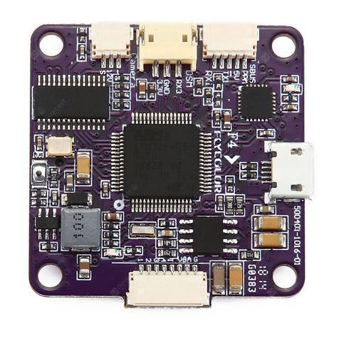
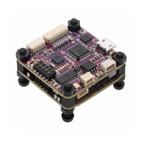
Flight Controller
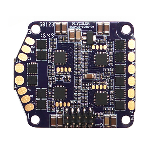
● MCU: STM3 2F405.
● Gyro MPU-6000 SP I.:
● FC firmware:Betaflight_OM N IBUSF 4
● Supports PPM ,SBU S,SP E K TRUM1024/2048 etc. remote control / receiving mode.
● FC integrated OSD, users can adjust OSD pa rameters via Betaflight configurator.
● FC integrated 3.3V,5V and V BAT for receiver, VTX, camera, buzzer, LED and other peripheral devices.
● Provided several cables for peripheral devices such as V TX, camera etc. And will give you an unprecedented
experience for assembly;
● Install holes: 20x20mm,M2.
01 Main features
02 Specifications
Raptor S-Tower F4-20A 20A 30A 2-4S
Con. Current Burst Current
(10S) F.C Vout Size
(For reference)
Weight
LiPo cells Typical Applications
(For reference)
Model
120-180 Multi
03 Part list / Dimensions
1.For quick plug, Fligh t Controller additi on ally provide:
●One 6p cable (6-pin SH 1.0 termi nal) for the power & signal
between ESC and Fli ght controller;
●One 3p cable (4-pin SH 1.0 termi nal) for S BUS receivers ;
●One 3p cable (4-pin SH 1.0 termi nal) for P PM receivers;
●One 5p cables(5-pin SH1 .0 terminal) for LE D,Buzzer;
● For these quick plug cables, please confirm the wire sequences on your devices’ connector are corresponding with the Flight
contro ller’s before connecting. If the terminals are not fit your devices ,pl ease make a modified connection to fit.
● Please ensure all solder joints & wires are insulated well, as short circuit will damage the product.
● Please ensure enough safety space between the ES C& Drone frames, as short circuit will damage the product.
● Never use this product in harsh environments such as humidity, high temperature, and so on to avoid product damage
*All pictures are for refe rence only
All soldering tasks require good soldering ●
technique,short circuit between components
or wires should be avoided at any time.
Please ensure all solder joints are insulated ●
with heat shrink where necessary.
●Please double-check the polarity is correct
before power up.
F.C
● User needs to calibrate the throttle range when starting to use a new ESC or
another transmitter. When the input signal is Dshot, throttle calibration is
disabled.
● BLHeli-S firmware, please don't flash any other firmware except “F-H-40”.
● Please do not exceed the ESC current range.
● Observe polarity at all times. Check and double check before applying power.
● Power off before unplugging ,plugging in or making any connections.
● Keep magnets away from the Flight Controller.
● Do everything you can to prevent vibrations.
251400-1096 V1.2
04 Connect diagram of E SC and FC
User Manual
Multi-Rotor Brushless ESC
F11
Zadig 2.3.701
STM32 BO OTLO ADER
ST Tub30 (v3.0.4.0)
0483 D
X
8 devi ces found
Replace Driver
Options
RAPTOR
S- TO WE R
F4
M3
Battery V-
Battery V+
3#Motor
M4
4#Motor
2#Motor
1#Motor
V-
V+
M1 M2
4
3
2
1
V
G
ESC-Flight Control
SBUS/
PPM
receiver
GND
5V
SBUS
PPM
BOOT U S B
S4
S3
S2
S1
VBAT
GND
3.3V
GND
DSM
SPEKT R UM
receiver
GDN
5V
LED
B+
B -
GND
5V
SBUS
PPM
3.3V
GND
DSM
S4
S3
S2
S1
VBAT
GND
GND
VBAT
Camera
Video
Rx6
Tx6
Tx3
Rx3
GDN
5V
GND
VBAT
Camera
Video
UART6-RX
UART6-TX
UART3-TX
UART3-RX
GDN
5V
S4
S3
S2
S1
VBAT
GND
ESC
ESC-Flight Control
Dimensions
20 mm
28 mm
31.2 mm
31.6 mm
20 mm
17 mm
1
2
3
3
4
5
6
1
2
3
4
5
1
1
8
4
4
4
6
Description Qty.
Item
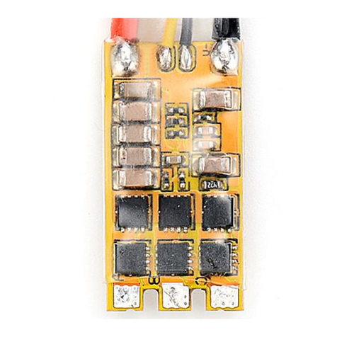
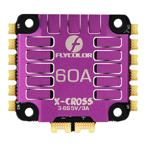
Raptor BLS 20A 4in1 E S C
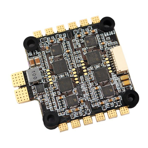
F4 Flight Controller
Silicon spacer
Nylon nut M2
Plastic spacer
Screw M2*22
31.6x31.2x17mm14.6g3.3V,5V
GDN 5V LED B+ B-

