Renegade Blue 328 Manual

Blue|328 and Blue 328|MXE
Digital Audio Mixer
Operator’s Guide
Software Version: 2

Renegade Labs Blue|328
Publishing and Copyright Information
Blue|328 and Blue 328|MXE Operator’s Guide
Part Number 070- 000
Publishing History
Revision 5: November, 2012
Copyright
© Renegade Labs, Inc. 2005 - 2012. All rights reserved. No part of this
publication may be reproduced, transmitted, transcribed, stored in a
retrieval system, or translated into any languages in any form by any
means without the written permission of Renegade Labs.
otice
Information contained in this document is not guaranteed and is subject to
change without notice or obligation, and does not represent a
commitment on the part of Renegade Labs, Inc.
Company Information
Renegade Labs, Inc.
P.O. Box 86
Cedar Ridge, California 9592
United States of America
Voice: +(530) 273-70 7
Fax: +(530) 271-0757
Web: www.renegadelabs.com
email: [email protected]
Page 2

Operator’s Guide
Table of Contents
About this Operator’s Guide.........................................................................................5
Overview of the Blue|328 Mixer...................................................................................6
Overview of the Blue|328.......................................................................................6
About the Blue|328.................................................................................................
Blue|328 Audio Block Diagram...............................................................................8
Control Descriptions.....................................................................................................9
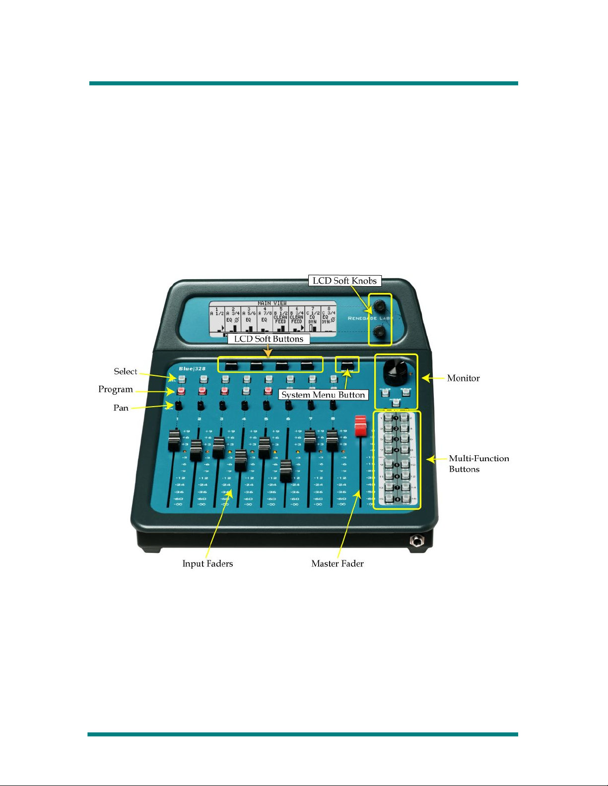
Control Panel Overview..........................................................................................9
The Blue|328 Control Panel Layout.........................................................................9
Display Controls...................................................................................................10
Monitor Control Section........................................................................................11
Button, Pan, and Fader Rows................................................................................12
Fader Strips .........................................................................................................12
Master Fader ....................................................................................................... 15
Multi-Function Keypad..........................................................................................16
Introducing Views and Menus ....................................................................................18
Views vs. Menus ..................................................................................................18
Navigating Views and Menus................................................................................19
LCD Views ................................................................................................................. 21
LCD View Tree......................................................................................................21
Overview..............................................................................................................21
Main View.............................................................................................................22
Route View........................................................................................................... 25
Meter View........................................................................................................... 26
Fader Level View..................................................................................................28
System Adjustments and Information Display............................................................29
System Menu Tree................................................................................................29
Accessing the System Menus...............................................................................29
Assigning Record Returns.....................................................................................30
Adjusting the Headphone Output.........................................................................31
Enable/Disable TONE............................................................................................33
Selecting Reference Sync.....................................................................................33
Making Digital Audio Adjustments........................................................................34
Adjusting Panel LED Intensity and Panel Modes...................................................35
Displaying System Information.............................................................................36
Configuring Output Functionality..........................................................................36
View and Adjusting Module Parameters................................................................42
Loudness Monitoring............................................................................................4
Making Fader Assignments .......................................................................................50
Making Fader Input Assignments .........................................................................50
Setting Up Fader Output Routing .........................................................................53
Applying Audio Effects............................................................................................... 56
Applying Equalization...........................................................................................5
Applying Dynamics ..............................................................................................59
Overview of Dynamics Controls ...........................................................................60
Applying Audio Delay ..........................................................................................65
Applying Phase Reversal......................................................................................6
Enabling Clean Feed ............................................................................................68
Adjusting Input Gain Trim .................................................................................... 0
Monitoring Control..................................................................................................... 1
Page 3

Renegade Labs Blue|328
Monitoring Program Bus....................................................................................... 1
Setting Up Solo bus Monitoring............................................................................. 1
Monitoring Record Returns................................................................................... 1
Setting up the Monitor Mode................................................................................ 2
Memory Save/Recall ..................................................................................................80
What is stored during a Memory Save..................................................................80
Memory Save/Recall Operations...........................................................................81
USB Register Management (328|MXE only)................................................................84
USB Register Management Overview...................................................................84
Register Management Menu.................................................................................84
Transfer Registers To/From USB Memory Device..................................................84
Deleting Registers................................................................................................8
Rename or Create new USB directory..................................................................88
USB Register Directory Overview.........................................................................89
Software Upgrade using USB Memory Device......................................................89
Appendix A: Installation Information..........................................................................91
Input/Output Configuration...................................................................................91
Mixer Rear Panel Detail .......................................................................................91
Appendix B: Assigning Single Channels......................................................................93
Appendix C: Diagnostic Port/GPI Option.....................................................................94
Diagnostics Port................................................................................................... 94
GPI Interface (Optional)........................................................................................95
Index ......................................................................................................................... 9
Page 4

Operator’s Guide
About this Operator’s Guide
Welcome to the Blue|328 and Blue 328|MXE digital audio mixers! The
Blue|328 and the Blue 328|MXE operations are exactly the same other
than the Blue 328|MXE includes the ability to transfer registers to and
from a USB memory device. This Operator’s Guide refers to all
operations as Blue|328 with the exception of the section pertaining to the
Blue 328|MXE USB register management.
Note
To get up and running immediately, please consult the JumpStart Guide.
For detailed installation information, for example how to add input or
output modules to your mixer, please consult the Installation Guide.
This Operator’s Guide covers the following subjects:
•Overviews
•Control Descriptions
•LCD View and Menu Descriptions
•System adjustments and Information Display
•Fader Assignments
•Applying Audio Effects
•Monitoring Control
•Memory Save/Recall
•USB Register Management for Blue 328|MXE only.
This guide also includes an appendix containing some installation details
you may need to refer to from time to time.
About this Operator’s Guide Page 5

Renegade Labs Blue|328
Overview of the Blue|328 Mixer
Overview of the Blue|328
The Blue|328 digital audio mixer is designed for use in professional audio
for video applications. NLE edit suites, Telecine bays, Mobile Trucks, and
similar applications benefit greatly from the wealth of capabilities provided
by the Blue|328.
Note
The Blue|328 is a self-contained standalone mixer whereas the Blue
328|MXE has a separate audio engine chassis connected to a separate
Blue control panel via a Ethernet cable. All input and output functionality
is the same between the two products.
Inputs and Mixing
Optional input modules allow up to 32 audio inputs. Four slots on the
back of the mixer accept either analog ( or 6 channel) or digital (8
channel) input modules, for a maximum of 32 channels. The mixer can
actively mix up to 16 channels of these inputs simultaneously, and send
them out over eight program output buses. Eight more program,
monitoring, or meter outputs can be added with an optional output
module.
Monitoring
The Blue|328 has eight analog monitor outputs and a headphone output.
Any combination of the program bus, solo bus, or record-returns can be
selected for listening on the monitor and/or headphone outputs.
Display
An LCD display allows mixer configuration and signal characteristics to be
viewed. In addition, a unique, user-friendly system of menus and variable-
function buttons provides basic fader setup and extensive audio effects to
be applied. This system allows a great deal of functionality to be placed in
a small, space-saving console.
Loudness Monitoring
The Blue|328 includes the ability to monitor the loudness level of the
audio using using ITU-R BS.1770-2 gated algorithm. The Loudness
Monitoring can either follow the monitoring mode or a custom set-up can
be created.
Feature Summary
•Accepts analog or digital audio.
Page 6 Overview of the Blue|328 Mixer

Operator’s Guide
•Digital inputs may be AES or SD/HD SDI (serial digital with embedded
audio).
•Accepts up to 32 input channels with optional input modules.
•Mixes 16 channels simultaneously.
•Has eight program outputs.
•Loudness Monitoring using ITU-R BS.1770-2 gated algorithm.
•Has eight highly configurable monitor and stereo headphone outputs.
•Optional output module can be added for additional program, monitor,
or meter outputs.
•Has powerful LCD menu system with space-saving variable-function
buttons for fader setup and applying audio effects.
About the Blue|328
The Blue|328 is operated manually. The following figure shows a typical
Blue|328 installation in a non-linear edit suite.
Figure 1. Blue|328 in Video Edit Suite
Overview of the Blue|328 Mixer Page 7

Renegade Labs Blue|328
Blue|328 Audio Block Diagram
The following diagram represents the audio flow through the Blue|328
Digital Audio Mixer.
Figure 2. Flowchart for Blue|328
Page 8 Overview of the Blue|328 Mixer

Operator’s Guide
Control Descriptions
Control Panel Overview
The control panel provides access to the many features of the mixer.
Intelligent software helps cut down on the number of button presses you
need to get the job done. Buttons with multiple functions expand the
mixer’s capability.
This section provides a quick look at the control panel of the Blue|328.
The sections that follow describe the controls in more detail.
The Blue|328 Control Panel Layout
Figure 3. Blue|328 Control Panel La out
Control Descriptions Page 9

Renegade Labs Blue|328
Display Controls
Figure 4. Displa Controls
The Display Controls include the LCD display, supported by buttons and
knobs that allow you to navigate through and make selections within the
Views and Menus that appear on the display. The Views and Menus allow
you to keep track of how your mixer is set up, View characteristics of
input signals, make changes to your mixer’s setup, and apply effects to
audio (also see “Introducing Views and Menus” on page 18).
System Menu Button
Pressing this button brings up the System Menus on the LCD display.
System Menus are for making system-wide changes and for Viewing
certain kinds of system information (also see “Introducing Views and
Menus” on page 18). The Menu button is a toggle switch; pressing it
again exits the System Menus.
Soft Buttons
These four buttons are used for making selections on Views and Menus,
as shown in the example below. These are named “soft” buttons because
their functions change according which View or Menu is displayed. The
position of each corresponds to one of the virtual buttons (soft keys) in
the display.
Soft Knobs
The two rotary soft knobs (upper and lower) are used to change
parameters in many of the display menus, as shown in the example
below. These are named “soft” knobs because their functions change
according which menu is displayed.
Page 10 Control Descriptions

Operator’s Guide
Monitor Control Section
Figure 5. Monitor Controls
The Monitor controls allow you to precisely configure your monitoring
environment.
Monitor Knob
The Monitor Knob is for setting the monitor output level. Turning the knob
clockwise raises the output level; turning the knob counterclockwise
lowers the output level.
Calibration LED
The Calibration LED indicates when the monitor output level is at unity.
The Monitor Knob's reference indicator line also points at the Calibration
LED when at unity.
MUTE button
The MUTE button mutes all eight monitor outputs when pressed.
Pressing the MUTE button again un-mutes the monitor outputs.
MODE Button
The MODE button allows you to select or set up various monitor output
matrix configurations (modes) using the Monitor Mode Menu (See
“Setting up the Monitor Mode” on page 72). The modes determine how
the eight program outputs are routed to the eight monitor outputs.
Note
The level of the headphone output is independent of the Monitor knob
setting or MUTE button state. See “Adjusting the Headphone Output“ on
page 31 for more information regarding the headphone output.
Control Descriptions Page 11

Renegade Labs Blue|328
SOLO Button
On the Blue|328, the SOLO button allows you to monitor one or more
selected faders separately from the entire mix. The program outputs are
not affected.
When pressed, normal monitoring is interrupted and the solo mode is
entered. The Select buttons are used to select which fader(s) will be
monitored. The SOLO button is toggle on/off; pressing it again will exit the
solo mode and return normal program output monitoring.
Note
The solo output routing follows fader output routing.
SOLO will override the Record Return monitoring when enable. Refer to
“Assigning Record Returns“ on page 30 for additional information.
•Also see “Setting Up Solo bus Monitoring” on page 71.
Button, Pan, and Fader Rows
Select Button Row
The Select buttons are for selecting individual faders for performing a
function, for example adding equalization to a fader’s audio. There is one
Select Button for each fader. For detail, see “Fader Strips” on page 12.
Program Button Row
The Program buttons are used to place faders’ audio on the program
output bus to which the fader has been assigned. There is one Program
button for each fader. For detail, see “Fader Strips on page 12.
Pan Pot Row
All fader inputs are stereo, so each fader has a pan pot to adjust the
fader’s audio signal between two assigned output channels. For detail,
see “Fader Strips” on page 12.
Faders Row
There are eight stereo faders for adjusting audio gain. The faders are
numbered 1 through 8 beginning from the left. For detail, see “Fader
Strips on page 12.
Fader Strips
A fader strip comprises a fader, a unity LED, a Pan Pot, a Program
button, and a Select button.
Page 12 Control Descriptions

Operator’s Guide
Figure 6. Fader Strip
Fader
The fader adjusts the output audio level of its stereo inputs. The fader
can adjust the output level from +9dB to -∞. Each fader is assignable to
any input, can be routed to any of the Program outputs, and can be
panned between its two audio channels. The signal through the faders
can be compressed/expanded, equalized, delayed, phase reversed, gain
trimmed, or set to a clean feed (unmodified) for dubbing purposes.
Unity LED
The Unity LED lights up when the fader is set at unity gain.
During Memory Recalls, the Unity LED has these functions:
•The Unity LED is red when the physical position does not match the
audio position.
•The Unity LED is yellow when the audio level is at unity.
•The Unity LED is off when the physical position matches the audio
position and the audio level is not at unity.
Pan Pot
The pan pot allows you to adjust the fader’s audio output between the
odd and even output buses. Because any input can be routed to any of
Control Descriptions Page 13

Renegade Labs Blue|328
the eight output buses, the behavior this seemingly simple pan can be
complicated.
As an example, consider the usual case where output bus 1 is the left
monitor output and output bus 2 is the right monitor output. Suppose the
left input is routed to output bus 1 only, and the right input is selected on
bus 2 only. Turning the pan knob fully counterclockwise would yield only
left input audio from the left speaker. With the pan knob fully clockwise,
we would hear only right input audio from the right speaker.
However, if you route the left input channel of the fader to output bus 2
and the right input channel to output bus 1, the pan pot may behave
differently than you expect. Turning the pan knob fully counterclockwise
yields the right input channel only in the left speaker. This is due to the
right input channel being routed to the odd numbered output channel.
Since the pan knob works based on the assigned output channels,
whichever source is routed to the odd output channels is what is heard.
Turning the pan knob fully clockwise yields the left input channel only in
the right speaker. This is due to the left input channel being routed to the
even numbered output channel. Since the pan knob works based on the
assigned output channels, whichever source is routed to the even output
channels is what is heard.
Program Button
The Program button places the fader’s output onto the program bus. The
specific program outputs on which the fader’s channels will appear is
determined by the output routing for the fader. See “Setting Up Fader
Output Routing “on page 53.
The Program button is toggle on/off. The Program button indicates that its
associated fader is on the Program bus by lighting up.
Select Button
The Select button has various functions with regard to its associated
fader, for example:
•Selecting the fader for certain operations, for example applying audio
effects.
•Bringing up menus for making changes to the fader’s audio input
signals.
If no input is assigned to the fader, pressing the Select button
brings up the Input Assignment Menu on the display.
If the fader has inputs assigned to it, the Select button accesses
the various menus, with the Route Menu as the default menu.
The Select button is a toggle on/off. When the Select button is active, it is
illuminated.
Note
De-selecting the Select button in a menu sequence often is equivalent to
pressing the enter key on a pc. It can cause changes to be accepted.
Page 14 Control Descriptions

Operator’s Guide
Master Fader
The Master Fader is used for adjusting the overall gain of all eight
Program outputs. The gain settings of individual faders are not affected
by the Master Fader.
Figure 7. Master Fader
The Master Fader range is from 0dB (unity) to -∞. The Master Fader has
no unity LED, since bringing the fader all the way to the top of its travel is
unity.
When the master fader is set to 0dB (the top of its travel), the program
output audio will be at unity gain with respect to the levels from individual
faders.
When the Master Fader is brought down, the program output gain will be
reduced by the amount of fader attenuation. The individual faders’
respective gain settings will follow. In other words, if fader #1 is set to
+6dB and the Master Fader is set to -3dB, fader #1’s actual output level
will be +3dB.
Note
The Master Fader will not effect faders that are set to Clean Feed Mode.
See “Enabling Clean Feed“ on page 68 for more information.
Control Descriptions Page 15

Renegade Labs Blue|328
Multi-Function Keypad
Figure 8. Multi-Function Ke pad
The Multi-function Keypad is a set of buttons that is available for use in
many operations. Here are some examples:
•Headphone output bus routing
•Fader input assignment
•Program output routing
•Monitor routing and configuration
•Memory save/recall
The Multi-function Keypad provides a means for making selections and
for indicating the presence of audio on specific channels.
The Multi-function Keypad is laid out to correspond with the input module
slots, labeled A, B, C, and D on the rear panel of the mixer. Small
buttons that light represent the possible stereo channels (1/2, 3/ , etc.)
In addition, the keypad is numbered down its middle with numerals 1
through 8, for using the keypad to indicate or select program outputs.
Page 16 Control Descriptions

Operator’s Guide
Figure 9. Multi-function Ke pad La out
The multi-function keypad may be used in conjunction with the Select
buttons to indicate (or designate) which audio channels are applied to a
fader. When the Select button for an individual fader is pressed, the audio
assigned to it will be indicated on the multi-function keypad. The system
menus must be closed for this to occur.
Note
In some applications, the Multi-function Keypad may be used differently
than described above. Such uses will be described in the related
procedures.
Control Descriptions Page 17

Renegade Labs Blue|328
Introducing Views and Menus
The LCD screen on the Blue|328 can display control panel configurations
and many signal conditions. It can also display menus that allow you to
make changes. There are two types of displays, Views and Menus.
Views vs. Menus
Views
Views are displays that show the current status of the mixer. They do not
provide a way to make changes. See the example below.
Figure 10. View Example, Meter View
This example displays the audio signal levels for each Program output.
Menus
Menus are displays that allow you to not only View status, but also make
changes. See the example below.
Figure 11. Menu example, Digital Audio Menu
The example above allows you to select the audio sample rate.
There are three sets of menus in the Blue|328.
•System Menus. These generally allow you to change global settings
as well as observe certain system information. System Menus are
activated using the MENU button on the control panel.
•Select Button Menus. These generally allow you to make fader-
specific settings, such as applying audio effects to the signals through
a fader. The Select Button Menus are described in the procedures
where they are used. Select Button Menus are activated using the
SELECT buttons associated with the faders.
Page 18 Introducing Views and Menus

Operator’s Guide
•Monitor Mode Menus. These allow you to set the output matrix that
feeds the monitor outputs. The Monitor Mode Menus are described in
Setting up the Monitor Mode on page 72. Monitor Mode Menus are
activated by pressing the MODE button in the Monitor section of the
control panel.
avigating Views and Menus
Basic avigation
The default display is the Main View (see below).
Figure 12. Main View
Pressing the System Menu button brings up the System Menus,
beginning with the first System Menu screen. Pressing it again returns
you to the Main View. When not in a System Menu, pressing one of the
fader Select buttons places you in the Select Menus.
Using Soft Buttons and Knobs
The Soft Buttons located below the LCD display correspond to “soft
labels” in Views and menus. See below. Use the soft buttons to make
selections within a menu, or to navigate to another display.
Figure 13. Main View with Soft Buttons
Soft Knobs are used to make adjustments or selections in some menus.
See below.
Introducing Views and Menus Page 19

Renegade Labs Blue|328
Figure 14. Example Menu with Soft Knobs
In this menu, frequency is adjusted using the Upper Soft Knob, and gain
is adjusted using the Lower Soft Knob. The position at the right side of the
display, with arrows, indicates that soft knobs are to be used. The vertical
position indicates which soft knob to use.
Page 20 Introducing Views and Menus
This manual suits for next models
1
Table of contents