2/7
1. Preface
This release note describes precautions and how to use the hardware included in the R0K303823A000BR.
2. Precautions (Be sure to read)
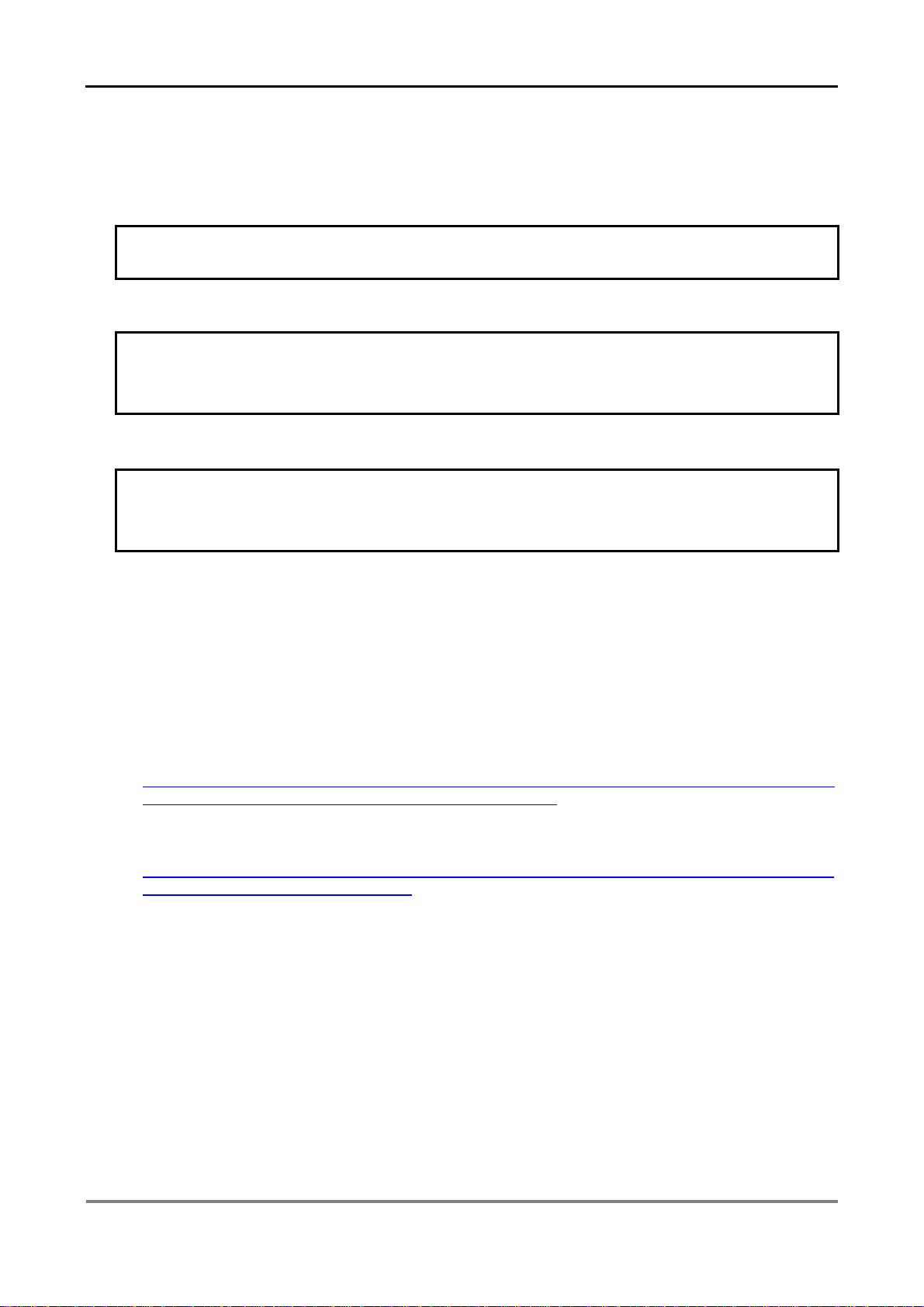
[Remove MCU]
When removing a microcomputer from the IC socket, in use of the IC socket board
(R0K303823A000BR), Please remove the MCU after turning the power OFF.
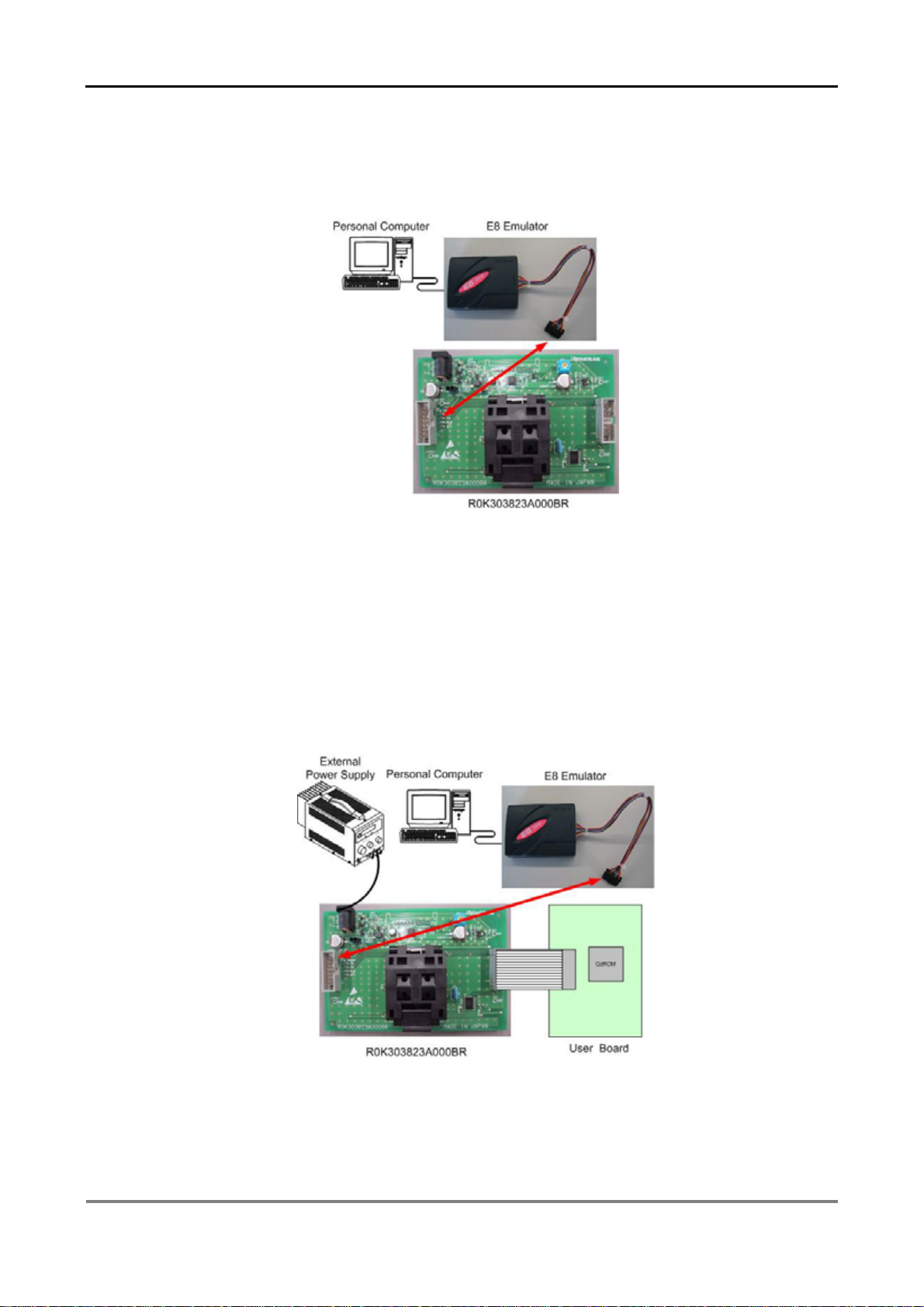
[Connect E8]
Please connect the communication connector of E8 to CN1 of the IC socket board
(R0K303823
000BR). Do not connect E8 to CN2 of the IC socket board. When connecting E8 to CN2
and using the IC socket board, the microcomputer and E8 may be damaged.
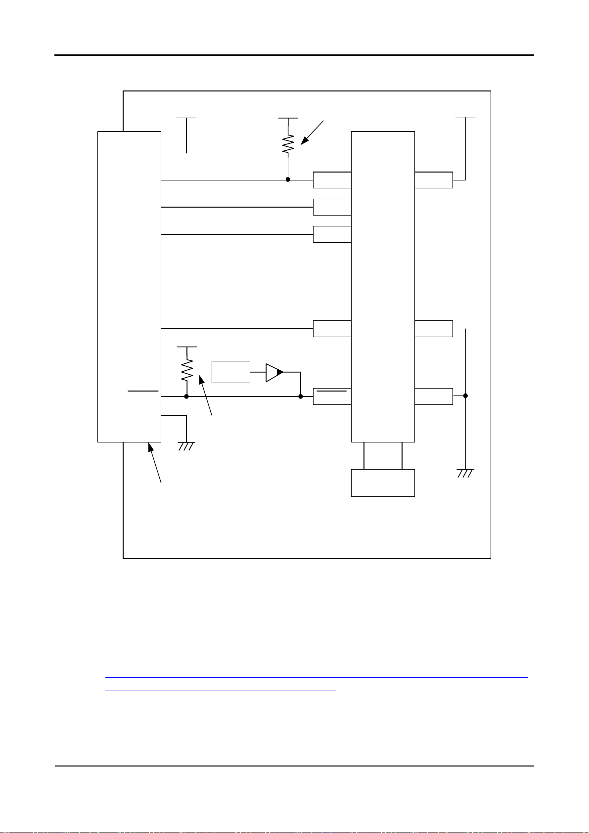
[Potential Meter]
Do not turn the volume (VR1) of the IC socket board (R0K303823A000BR). When turning the volume
(VR1), and then using the IC socket board, programming to QzROM may not be performed properly.
Also, the MCU may be damaged.
3. Product Overview
The 3823 Group IC socket board (R0K303823A000BR) is an IC socket board for programming to QzROM
with Flash Development tool Kit (FDT) and E8.
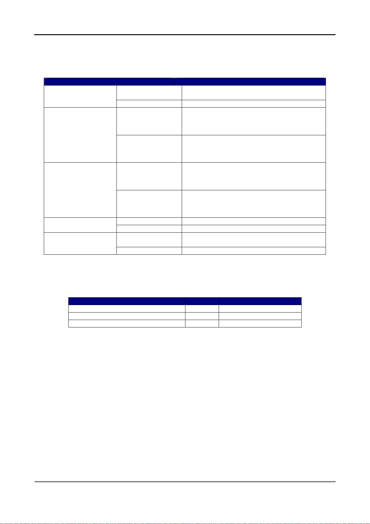
[Applicable Microcomputer]
3823 Group 80-Pin Version QzROM Microcomputer (Package : PRQP0080GB-A(80P6N-A))
[Applicable Flash Writers]
(1) Renesas Technology Corp.
⋅Flash Development tool Kit (FDT)
URL:
http://www.renesas.com/fmwk.jsp?cnt=flash_development_toolkit_mid_level_landing.jsp&fp=/product
s/tools/flash_prom_programming/flash_development_toolkit/
⋅E8 (R0E000080KCE00)
URL:
http://www.renesas.com/fmwk.jsp?cnt=e8_tools_product_landing.jsp&fp=/products/tools/emulation_d
ebugging/onchip_debuggers/e8/&site=i