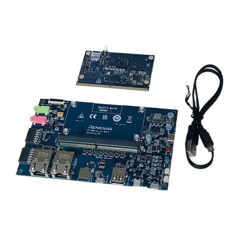
-R-EVK Evaluation Kit
R16UH0015EU0100 Rev.1.0
May 27, 2021
Page 1
© 2021 Renesas Electronics
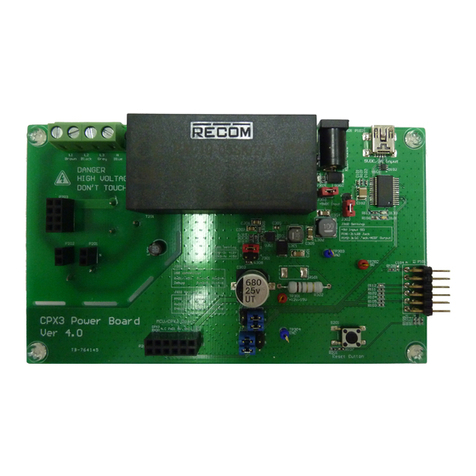
The P9415-R-EVK Wireless Power Evaluation Board serves to demonstrate the features and performance of the
9415-R 15W Wireless Power Receiver with WattShare™ mode. The P9415-R-EVK is designed for evaluation
purpose only. It must not be used for module or mass production purposes.
Contents
1. Features.........................................................................................................................................................3
2. Evaluation Kit Contents ...............................................................................................................................3
3. Overview........................................................................................................................................................3
4. Setup..............................................................................................................................................................4
4.1 Required or Recommended User Equipment.......................................................................................4
4.2 Required Software on Computer..........................................................................................................4
4.2.1. Software Installation...............................................................................................................4
4.3 Usage Guide.........................................................................................................................................5
4.4 Kit Hardware Connections for Rx Mode................................................................................................5
4.4.1. Start Guide for Rx Operation..................................................................................................5
4.5 Kit Hardware Connections for Wattshare (Tx) mode ............................................................................6
4.5.1. Start Guide for Wattshare Tx mode Operation.......................................................................6
4.5.2. WattshareTM Tx Mode Input Voltage.......................................................................................8
5. P9415-R Evaluation Board Test Point and Connector...............................................................................8
5.1 P9415-R Evaluation Board Test Point Placement................................................................................8
5.1.1. J1 Dongle Connector Pin Descriptions...................................................................................8
5.1.2. J5 Test Connector Pin Descriptions.......................................................................................9
6. Hardware Connections–Renesas USB-I2C Dongle to Window GUI.........................................................9
6.1 Using the Windows GUI......................................................................................................................12
7. TRx Wireless Power Coil............................................................................................................................15
8. Resonance Capacitors...............................................................................................................................15
9. PCLAMP Connection..................................................................................................................................15
10. Transient Voltage Suppressors.................................................................................................................15
11. GPIO and GPOD Pins.................................................................................................................................16
11.1 OD0/SCL Pin......................................................................................................................................16
11.2 OD1/SDA Pin......................................................................................................................................16
11.3 OD2/INT Pin.......................................................................................................................................16
11.4 OD3/ALIGN_X Pin and OD4/ALIGN_Y Pin........................................................................................16
11.5 GP0/PWRGD Pin ...............................................................................................................................17
11.6 GP1/Q Main Pin and GP3/Q Offset Pin..............................................................................................17
11.7 GP2/ External Thermistor Pin.............................................................................................................18
11.8 GP4/I2C Address Select Pin...............................................................................................................18
11.9 GP5/INHIBIT Pin ................................................................................................................................18
