8Quick Setup................................................................................................................55
8.1 Hardware setup........................................................................................................................................55
8.2Debug interfaces –SWD / JTAG.............................................................................................................56
8.3 Debug interfaces -–UART........................................................................................................................57
Figures
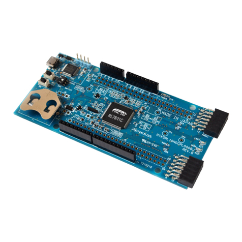
Figure 1: DA14706 PRO Development kit............................................................................................................7
Figure 2: System Block Diagram..........................................................................................................................8
Figure 3: Engineering level, voltage & interface, PRO-Motherboard block diagram............................................9
Figure 4: Monitoring Header J3: Schematic (left) & PCB (right).........................................................................10
Figure 5: Monitoring Header J4: Schematic (left) & PCB (right).........................................................................10
Figure 6: Debug interface including DIP switch SW1.........................................................................................11
Figure 7: PCB top of the DA1470x PRO Development Kit Top..........................................................................11
Figure 8: USB HUB Circuitry of DA14706 PRO-Motherboard............................................................................12
Figure 9: USB to UART (FTDI module)..............................................................................................................13
Figure 10: UART & SWD signals........................................................................................................................13
Figure 11: MK22 debugger schematic (for M33)................................................................................................14
Figure 12: J-Trace connector for M33................................................................................................................15
Figure 13: Audio section schematic....................................................................................................................15
Figure 14: Analog Switch (U8) used to isolate the Digital Audio interface.........................................................16
Figure 15: Expansion SPI connector (J27).........................................................................................................16
Figure 16: Voltage Level Translation Circuit.......................................................................................................17
Figure 17: Push Buttons used in the DA1470x PRO-Motherboard....................................................................18
Figure 18: QSPI RAM schematic........................................................................................................................23
Figure 19: QSPI RAM Analog Switch.................................................................................................................23
Figure 20: QSPI RAM power switch...................................................................................................................24
Figure 21: Default QSPI flash AT25SL128A-MHE-T..........................................................................................24
Figure 22: Two QSPI Flash PCB footprint options (not populated)....................................................................25
Figure 23: Analog switch (U6) used for the QSPI flash signals..........................................................................25
Figure 24: QSPI Flash power switch ..................................................................................................................26
Figure 25: eMMC connector schematic..............................................................................................................27
Figure 26: Power configuration applied on PRO-Motherboard ..........................................................................28
Figure 27: VLDOp voltage generation................................................................................................................28
Figure 28: 3.3V LDO for PRO-Motherboard peripherals....................................................................................29
Figure 29: Power Measurement Module (PMM2) block diagram.......................................................................31
Figure 30: Current Measurement socket (M2)....................................................................................................32
Figure 31: the hardware setup for current measurements.................................................................................33
Figure 32: C_TRIG selection jumper block (J7) & buffer MOSFETS for I/O levels compatibility.......................34
Figure 33: PMM2 current Measurement Circuit PMM2......................................................................................35
Figure 34: PMM2 on board peripherals (Power supply, Memory etc.)...............................................................36
Figure 35: Current measurement unit PCBA (TOP)...........................................................................................37
Figure 36: Normal mode (1μA to 500mA at 3.3V) data after offset calibration. .................................................38
Figure 37: Hibernation mode (100nA to 60uA at 3.3V) data after offset calibration. .........................................38
Figure 38: Power connections............................................................................................................................39
Figure 39: Header schematic for LCD daughterboard (Interface board)............................................................40
Figure 40: LCD add-on daughterboard...............................................................................................................41
Figure 41: QSPI AMOLED LCD daughterboard position on PRO-Development kit ..........................................42
