Renishaw UCClite-2 User manual

UCClite-2 and UCClite
Installation guide
H-1000-5109-02-A

© 2006 - 2008 Renishaw plc. All rights reserved.
This document may not be copied or reproduced in whole or in part, or
transferred to any other media or language, by any means, without the prior
written permission of Renishaw.
The publication of material within this document does not imply freedom from
the patent rights of Renishaw plc.
Disclaimer
Considerable effort has been made to ensure that the contents of this
document are free from inaccuracies and omissions. However, Renishaw
makes no warranties with respect to the contents of this document and
specifically disclaims any implied warranties. Renishaw reserves the right to
make changes to this document and to the product described herein without
obligation to notify any person of such changes.
Trademarks
RENISHAW® and the probe emblem used in the RENISHAW logo are
registered trademarks of Renishaw plc in the UK and other countries.
apply innovation is a trademark of Renishaw plc.
All brand names and product names used in this document are trade names,
service marks, trademarks, or registered trademarks of their respective owners.
Renishaw part no: H-1000-5109-02-A
Issued: 03 2008

UCClite-2 and UCClite
installation guide

2 FCC
FCC (USA only)
Information to user (FCC section 15.105)
This equipment has been tested and found to comply with the limits for a class A digital device, pursuant
to part 15 of the FCC rules. These limits are designed to provide reasonable protection against harmful
interference when the equipment is operated in a commercial environment. This equipment generates,
uses and can radiate radio frequency energy and, if not installed and used in accordance with the
installation manual, may cause harmful interference to radio communications. Operation of this equipment
in a residential area is likely to cause harmful interference, in which case you will be required to correct the
interference at your expense.
Information to user (FCC section 15.21)
The user is cautioned that any changes or modifications not expressly approved by Renishaw plc or
authorised representative could void the user’s authority to operate the equipment.

EC declaration of conformity 3
EC declaration of conformity
The UCClite and UCClite-2 has been manufactured in conformity with the following standards:
BS EN 61326:1998 Electrical equipment for measurement, control and laboratory use – EMC
A1:1998 / A2:2001 requirements.
Immunity to Annex A - industrial locations.
Emissions to class A (non-domestic) limits.
BS EN 60204-1:1998 Safety of machinery - Electrical equipment of machines
Part 1: General requirements.
and that it complies with the requirements of the following EC Directives (as amended):
89/336/EEC - Electromagnetic compatibility (EMC)
73/23/EEC - Low voltage

4 Care of equipment
Care of equipment
Renishaw probes and associated systems are precision tools used for obtaining precise measurements
and must therefore be treated with care.
Changes to Renishaw products
Renishaw reserves the right to improve, change or modify its hardware or software without incurring any
obligations to make changes to Renishaw equipment previously sold.
Warranty
Renishaw plc warrants its equipment for a limited period (as set out in our Standard Terms and Conditions
of Sale) provided that it is installed exactly as defined in associated Renishaw documentation.
Prior consent must be obtained from Renishaw if non-Renishaw equipment (e.g. interfaces and/or cabling)
is to be used or substituted. Failure to comply with this will invalidate the Renishaw warranty.
Claims under warranty must be made from authorised service centres only, which may be advised by the
supplier or distributor.
Trademarks
Windows XP and Windows 2000 are registered trade names of the Microsoft Corporation.
All trademarks and trade names are acknowledged.

References and associated documents 5
References and associated documents
It is recommended that the following documents are referred to when installing the UCClite-2 or UCClite.
Renishaw documents
Associated documentation is available from UCCserver.com website.
Document number Title
H-1000-5068 SPA1 installation guide
H-1000-5107 SPAlite installation guide
H-1000-5234 SPA2installation guide
H-1000-5247 SPA2-2 installation guide
H-1000-5067 MCU installation and user’s guide
H-1000-5227 SPA1 servo tuning user’s guide
H-1000-5246 Digital SPA tuning guide
H-1000-5224 UCCassist user's guide
External documents
National and international standards including the following may be applicable to the finished machine or
installation: -
EN ISO 12100-2:2003 (Safety of machinery - Basic concepts, general principles for design - Part 2:
Technical principles).
EN (IEC) 60204-1:1997 (Safety of machinery - Electrical equipment of machines - Part 1: General
requirements).

6 Safety
Safety
CAUTION: The UCClite-2 and UCClite controllers should be bonded to other conductive parts of
the installation using the earthing terminal located on the rear panel of the enclosure.
Electrical requirements
The UCClite-2 and UCClite are powered from an external PSU with an output of 24 V dc ±5% at 2.5 A
maximum or it can be powered from the SPAlite through the SPA connector cable.
Environmental conditions
Indoor use IP30* (BS EN 60529:1992)
Altitude up to 2000 m
Operating temperature +5 °C to +50 °C
Storage temperature -25 °C to +70 °C
Relative humidity 80% maximum (non-condensing) for temperatures up to +31 °C
Linear decrease to 50% at +40 °C
*NOTE: It may be necessary to house the UCClite-2 or UCClite in a suitable electrical enclosure
according to the installations environmental conditions.
WARNING: Earthing provisions for the complete machine is the responsibility of the OEM or
installer.
Isolation: UCClite-2 and UCClite are isolated by removing the power connector. It is the
responsibility of the installer or user to fit additional means of isolation if indicated by risk
assessment.
Earth fault/residual current protection: It is the responsibility of the OEM or product installer to
ensure an adequate level of protection for the complete machine installation.
!
!

Contents 7
Contents
1. Introduction.......................................................................................................................................11
1.1 Overview................................................................................................................................11
1.2 CMM host computer...............................................................................................................12
1.3 Installation software ...............................................................................................................12
1.3.1 Renicis....................................................................................................................12
1.3.2 UCCassist...............................................................................................................12
1.3.3 Licence key manager..............................................................................................12
1.3.4 Joystick set-up (UCClite only).................................................................................12
1.3.5 Joystick display window (UCClite only) ..................................................................13
1.3.6 UCClite-2 system components...............................................................................13
2Description of the UCClite-2.............................................................................................................15
2.1 UCClite-2 features..................................................................................................................15
2.1.1 TTP interface..........................................................................................................15
2.2 Power supply unit...................................................................................................................15
2.3 Joystick ..................................................................................................................................15
3Installation of the UCClite-2 components.........................................................................................17
3.1 General wiring standards.......................................................................................................17
3.1.1 Preparations ...........................................................................................................17
3.2 Connecting UCClite-2 cables to and from CMM....................................................................18
3.3 Connecting the UCClite-2 power supply................................................................................18
3.3.1 Connection to the SPAlite power supply.................................................................18
3.3.2 Connection to an external power supply.................................................................18
4Connecting the UCClite-2 to the host PC.........................................................................................19
4.1 Software installation (UCClite-2 only) ....................................................................................19
4.2 Software installation (UCClite only)........................................................................................19
4.3 UCClite-2 USB connection.....................................................................................................20
4.4 DCC upgrade.........................................................................................................................20
4.5 Downloading ..........................................................................................................................21
5Connecting the UCClite-2 to a CMM................................................................................................22
5.1 The controller 24 V supply .....................................................................................................24
5.2 Motor engagement via SPA connector ..................................................................................24
5.2.1 Amplifier enabling...................................................................................................24
5.2.2 Contactor energising...............................................................................................25
5.3 Motor command signals.........................................................................................................25
5.4 Motor command polarity.........................................................................................................26
5.5 Switched outputs....................................................................................................................26
5.6 Switched inputs......................................................................................................................26

8Contents
5.6.1 Limit switches......................................................................................................... 26
5.6.2 Amplifier OK and contactor feedback .................................................................... 27
5.6.3 Air pressure and crash switch (Fatal faults)........................................................... 27
5.6.4 Emergency stop (Fatal fault).................................................................................. 27
6Connectors and signals................................................................................................................... 28
6.1 Overview ............................................................................................................................... 28
6.2 CMM readhead input connections......................................................................................... 28
6.2.1 CMM readhead interface circuit............................................................................. 30
6.3 USB connection..................................................................................................................... 31
6.4 Serial Comms........................................................................................................................ 31
6.5 PICS connector..................................................................................................................... 31
6.6 Analogue SPA connector...................................................................................................... 32
6.6.1 +24 V dc................................................................................................................. 33
6.6.2 Contactor ............................................................................................................... 33
6.6.3 Enable amps.......................................................................................................... 33
6.6.4 Axis command signals........................................................................................... 33
6.6.5 Command common................................................................................................ 33
6.6.6 Reserved................................................................................................................ 33
6.6.7 Contactor feedback................................................................................................ 33
6.6.8 AMPs OK............................................................................................................... 33
6.6.9 ESTOP tripped....................................................................................................... 34
6.6.10 0 V (24 V return) .................................................................................................... 34
6.7 Digital SPA connector A and B.............................................................................................. 34
6.8 Machine I/O connector.......................................................................................................... 34
6.8.1 +24 V DC ............................................................................................................... 35
6.8.2 UCClite-2 general purpose output ......................................................................... 36
6.8.3 UCClite-2 general purpose inputs.......................................................................... 36
6.8.4 Amplifier OK input.................................................................................................. 36
6.8.5 CMM declutch........................................................................................................ 36
6.8.6 ESTOP tripped....................................................................................................... 37
6.8.7 Air pressure switch................................................................................................. 37
6.8.8 Crash switch .......................................................................................................... 37
6.8.9 Contactor feedback................................................................................................ 37
6.8.10 Limit switches......................................................................................................... 38
6.8.11 24 V return............................................................................................................. 38
6.9 MCU connector ..................................................................................................................... 38
7UCClite-2 troubleshooting ............................................................................................................... 39
7.1 Front panel LED displays...................................................................................................... 39

Contents 9
7.1.1 UCClite-2 power not switched ON..........................................................................39
7.1.2 UCClite-2 power switched ON................................................................................39
7.1.3 Initialisation/test......................................................................................................39
7.1.4 System file downloading.........................................................................................40
7.1.5 Servo active LED....................................................................................................40
7.1.6 Probe seated LED ..................................................................................................40
7.2 Fault finding............................................................................................................................40
7.2.1 Fatal faults..............................................................................................................40
7.2.2 Motors will not engage/re-engage ..........................................................................40
7.2.3 Motors disengage / relays chatter during move......................................................42
7.2.4 Poor positioning accuracy.......................................................................................43
7.2.5 Controller will not respond to host PC ....................................................................44
7.2.6 Motor stalling ..........................................................................................................45
7.2.7 Machine overspeed report......................................................................................45
7.2.8 Timing out during moves ........................................................................................46
7.2.9 Cannot start a move ...............................................................................................47
8Specifications ...................................................................................................................................48
8.1 Physical specification.............................................................................................................48
8.2 Cable lengths.........................................................................................................................48
8.2.1 UCClite-2 to CMM measuring scale readhead.......................................................48
8.2.2 UCClite-2 to CMM servo power amplifier input.......................................................48
8.2.3 USB cable link to PC ..............................................................................................48
8.3 Scale readhead signal speed.................................................................................................49
8.4 Electrical power requirements................................................................................................49
8.4.1 Controller output supplies.......................................................................................49
9System interconnections ..................................................................................................................50
9.1 Probing system interconnection.............................................................................................50
9.1.1 2 wire touch-trigger probe system for UCClite........................................................50
9.1.2 2 wire touch-trigger probe system for UCClite-2.....................................................51
9.1.3 TP200 touch-trigger probe system for UCClite.......................................................52
9.1.4 TP200 touch-trigger probe system for UCClite-2....................................................53
9.1.5 PH10 probe head and 2 wire touch-trigger probe system for UCClite....................54
9.1.6 PH10 probe head and 2 wire touch-trigger probe system for UCClite-2 ................55
9.1.7 PH10 probe head and TP200 trigger probe system for UCClite.............................56
9.1.8 PH10 probe head and TP200 trigger probe system for UCClite-2 .........................57
9.2 Servo amplifier connection.....................................................................................................58

10 Contents
9.2.1 UCClite and SPA1 ................................................................................................. 58
9.2.2 UCClite-2 and SPA1.............................................................................................. 59
9.2.3 UCClite and SPA2-2.............................................................................................. 60
9.2.4 UCClite-2 and SPA2-2........................................................................................... 61
9.2.5 UCClite and SPAlite............................................................................................... 62
9.2.6 UCClite-2 and SPAlite............................................................................................ 62
10 Joystick display window (only applicable for UCClite)..................................................................... 63
10.1 The window........................................................................................................................... 63
10.1.1 Behaviour............................................................................................................... 63
10.1.2 Viewing joystick settings........................................................................................ 63
10.2 Manual mode......................................................................................................................... 64
10.2.1 Axis lock................................................................................................................. 65
10.2.2 Probe trigger status................................................................................................ 65
10.2.3 CMM motors status................................................................................................ 66
10.2.4 Y+ Axis Orientation................................................................................................ 66
10.2.5 Active co-ordinate system...................................................................................... 66
10.3 Automatic mode .................................................................................................................... 67
10.4 User mode............................................................................................................................. 67
11 Joystick configurer (UCClite only) ................................................................................................... 68
11.1 Joystick USB connection (only required for UCClite)............................................................ 68
11.2 What is a configuration?........................................................................................................68
11.3 What is the default configuration?......................................................................................... 68
11.4 Joystick configuration (UCClite only)..................................................................................... 69
11.5 Setting up a configuration......................................................................................................69
11.5.1 Choosing a default................................................................................................. 69
11.5.2 Choose controls..................................................................................................... 70
11.5.3 View game controller control panel........................................................................ 71
11.5.4 Choose settings..................................................................................................... 72
11.5.5 Test settings........................................................................................................... 73
11.5.6 Saving the configuration ........................................................................................ 74
11.5.7 Print configuration.................................................................................................. 76
11.6 Adding a new configuration................................................................................................... 76
11.7 Changing configuration details.............................................................................................. 77
11.7.1 Changing an existing configuration........................................................................ 77
11.7.2 Changing the default configuration........................................................................ 77
11.8 Activating a configuration......................................................................................................77
12 Maintenance.................................................................................................................................... 78
13 Testing and verification.................................................................................................................... 79
14 Revision history............................................................................................................................... 80

Introduction 11
NOTE:
This document has been updated to cover the introduction of the UCClite-2
controller. Unless otherwise stated all references to the UCClite-2 also apply to
the UCClite.
1. Introduction
The purpose of this chapter is to describe the UCClite-2 (universal CMM controller) and the available
options.
1.1 Overview
The UCClite-2 is an addition to the Renishaw CMM controller product range. Utilising the UCC1 platform
introduced in 1997, the UCClite-2 offers similar system performance and capability.
The complete range of Renishaw 2 wire kinematic touch-trigger probes is supported. Conventional
contact and strain-gauge sensors, manual and motorised probe heads with appropriate probe or stylus
changers, only with supporting hardware (i.e. PH10 head will need a PHC10-2 which will be connected to
the serial comms port on the UCClite-2).
The UCClite-2 comprise of a controller in a 19 inch rack-mountable enclosure with a processor based
computer system. It is coupled to the CMM host computer by a USB 1.1 link and to the CMM by external
cable interface connectors.
The UCClite-2 CMM controller has the capability of:
•Controlling three axes of a CMM (accepting digital readhead signals and generating three axes drive
motor control signals)
•Accepting input signals from emergency stop, air pressure, crash detector, contactor feedback,
amplifier faults and all axis inner and outer travel limit switches
•Accepting two uncommitted general purpose input signals and generating one uncommitted general
purpose output signal
•Serial communication for use with a Renishaw PHC10 controller
•Directly supporting the TP1, TP2, TP6, TP20 touch-trigger probes
•Indirectly supporting the TP200 via an external PI200 interface
•Directly supporting the Renishaw SPAlite, SPA2or SPA1 servo power amplifier
•Providing a +24 V supply for use by the CMM switches
•The UCClite-2 supports the MCUlite joystick, it can also support the MCU1 and MCU5.
•The UCClite supports USB DirectX joysticks.

12 Introduction
1.2 CMM host computer
For the installation of a UCClite-2 controller, the CMM host computer must use Windows 2000 or Windows
XP Pro as an operating system and a hard disc drive with available storage space of at least 300 Mbytes.
The processor speed and RAM requirements are not excessive, if the PC supports the operating system
and application software, it will almost certainly support the UCC controller operation. A minimum
specification of 1 GHz processor speed and 256 Mb RAM is recommended.
For UCClite-2 only one free USB port is required as the MCU joystick plugs directly into the controller.
For UCClite the PC must have two free USB ports available for the communication and the system
joystick. It is recommended NOT to use a USB hub because of the reduction in speed of operation these
devices normally produce.
1.3 Installation software
1.3.1 Renicis
The Renishaw Renicis program is a utility to assist the engineer to install, commission and maintain a
CMM system based on the UCClite and UCClite-2 controllers.
It also has features which assist in the development of a software interface between any existing CMM
application program and the UCClite or UCClite-2.
Please refer to the Renicis user’s guide (Renishaw part number H-1000-5058) for more information on this
product.
1.3.2 UCCassist
The UCCassist software suite complements the Renicis software package offering the following additional
capabilities of:
•Basic machine system diagnostics
•Operation with Renishaw’s machine checking gauge, enabling the user to complete frequent
volumetric accuracy tests to ensure the CMM is running within the specified operational tolerances
•Automated CMM error mapping routines, when used in conjunction with the Renishaw ML10 or
XL80 laser systems
•Error mapping for manual machines
1.3.3 Licence key manager
This is a stand-alone software utility, which is used to check and update the licence for controller
functionality.
1.3.4 Joystick set-up (UCClite only)
This is a stand-alone software utility, which is used to check and modify the joystick operation when using
the UCClite system.

Introduction 13
1.3.5 Joystick display window (UCClite only)
This is a stand-alone utility, which shows the machine status, similarly to a MCU1 display screen. Please
refer to chapter 10 for more details. This utility is not required for UCClite-2 system.
1.3.6 UCClite-2 system components
The part numbers of the UCClite-2 kits and upgrades are:
1.3.6.1 UCClite-2 kits
A-5331-0008 UCClite-2 controller kit
A-5331-0201 UCClite-2 kit 1 comprising of:
A-5331-0008 UCClite-2 controller kit
P-EA02-0021 24 V PSU AC-DC
A-5331-0202 UCClite-2 kit 2 comprising of:
A-5331-0008 UCClite-2 controller kit
A-5331-0007 MCUlite joystick
A-5331-0004 UCClite DCC upgrade
A-5331-0006 UCC connector and bracket kit
A-5331-0010 SPAlite sales kit
A-5331-0203 UCClite-2 kit 3 comprising of:
A-5331-0008 UCClite-2 controller kit
A-5331-0007 MCUlite joystick
A-5331-0004 UCClite DCC upgrade
A-5331-0006 UCC connector and bracket kit
A-5121-0010 SPA23 axis DC system
P-EA02-0021 24 V PSU AC-DC
1.3.6.2 UCClite-2 upgrades
A-5331-0004 DC CMM operation functionality upgrade

14 Introduction
1.3.6.3 UCClite-2 accessories
P-EA02-0021 UCClite-2 power supply unit
A-5331-0007 MCUlite joystick (UCClite-2 only)
A-5331-0003 UCClite emergency stop pendant (UCClite only)
P-JS01-0004 DirectX compatible joystick (must be 3 axis joystick) (UCClite only)
A-1368-0100 PHC10-2 controller
A-1207-0010 PI 200 probe interface
1.3.6.4 UCClite-2 compatible servo power amplifiers
A-5355-0100 SPAlite digital servo power amplifier
A-5402-8302 SPA2-2 digital servo power amplifier

Description of the UCClite and UCClite-2 15
2 Description of the UCClite-2
2.1 UCClite-2 features
The unit has the following facilities:
•Rear panel connectors for the external interface cables to and from the CMM
•Rear panel USB connection for the two-way communication link to the CMM host computer
•Rear panel connection for a Renishaw MCU joystick (UCClite-2 only)
•Readhead circuitry for CMM digital measuring scales
•Axis servo control circuits
•Status indicating LEDs
•Control electronics for probes and peripheral devices attached to the CMM
LEDs visible through the front panel of the UCClite-2 enclosure indicate the operational status of the
UCClite-2.
Sub-circuits in the unit control the following interfaces through connectors on the rear panel of the
enclosure:
•USB data link to the CMM host computer
•X, Y, Z axis data input from the CMM readheads
•A communication loop (SPA-A and SPA-B) to the SPAlite or SPA2servo power amplifiers
•Connections for the TP20, TP1, TP2 and TP6 touch-trigger probes
•Signal outputs to the axis drive motors servo amplifiers of the CMM
•I/O connections to limit switches, air pressure and other digital inputs and outputs
2.1.1 TTP interface
The UCClite-2 unit incorporates the circuitry and software necessary to interface with the Renishaw TP20,
TP1, TP2 and TP6 probes.
2.2 Power supply unit
When the UCClite-2 is not connected to a SPAlite digital servo power amplifier it requires an external
24 V DC 2.5 amp power supply.
2.3 Joystick
UCClite-2 has an input for a MCUlite (or MCU1 / MCU5) joystick and therefore does not require a joystick
to be connected to a USB port on the system P.C
The UCClite does not have an input for a joystick control but the system will require one. The system has
been designed for use with a USB joystick connected directly to a USB port on the system P.C.

16 Description of the UCClite and UCClite-2
NOTE: Care should be taken to ensure that for UCClite systems the joystick is always plugged into the
same USB port that it was connected to when the joystick drivers were installed. If it is unplugged and
subsequently plugged into a different USB port then the drivers may have to be reinstalled.
CAUTION: If a wireless joystick is used they normally go to sleep when not in use to preserve
battery life. If the speed control is changed while the joystick is in sleep mode then unexpected
movement could occur when the joystick is woken up.
The UCC software installation includes two utility programmes for use with UCClite only:
1. A ‘joystick configurer’ utility, which allows the joystick directions and function switches to be
configured. The use of this utility is covered in chapter 11 of this manual.
2. A ‘joystick display’ window. This is a status window, similar to the screen on the MCU1 joystick,
that pops up on the P.C. screen. The use of this utility is covered in chapter 10 of this manual.
NOTE: UCClite-2 requires neither the ‘joystick configurer’ nor the ‘joystick display’ window utilities.
!

Installation of the UCClite and UCClite-2 components 17
3 Installation of the UCClite-2 components
The purpose of this chapter is to describe the procedure for installing the CMM controller and connections.
3.1 General wiring standards
To achieve reliable operation of the UCClite-2 and the CMM host computer, the following should be
observed:
•Scale readhead signals, reference marks and error signals should comply with EIA RS-422A. It is
recommended that each readhead has its own screened cable and that these cables are kept well
away from electrically noisy wiring such as motor supplies, etc.
•All opto-isolated inputs and outputs should be separate from other connections to the UCClite-2
controller, so that the CMM electrical system is kept isolated from the circuitry within the controller,
with the exception of the 0 V reference and protective grounding.
•All signal cables MUST be screened and all cable screens should be connected electrically to the
cable connector’s metal shells. Cable screens should only be connected to the protective earth (via
the connector shell) at the UCClite-2 and SPA end, and not directly connected to the CMM
protective earth. This is to avoid earth loops. However, the protective grounding must be continuous
between the controller and all other equipment in the installation. All cable connectors should be
secured to the UCClite-2 by the connector jack screws.
•See also the installation instructions supplied with other Renishaw components in the system,
i.e. probes or probe heads etc. Particular attention should be paid to the screening and earthing
methods of the cables carrying signals from probes.
NOTE: The UCClite-2 electronics 0 V rail is connected to the overall ground plane at a star point within
the UCClite-2.
3.1.1 Preparations
Before beginning the installation of the UCClite-2 check the following items:
•Ensure that all connecting cables, test equipment and software are available.
•Ensure that the CMM measuring scales/readheads are correctly installed and are functioning.
•Ensure that all the CMM status and limit switches etc. are correctly installed and have been function
checked.
•Ensure that all power has been removed from the CMM, the CMM host computer, CMM servo power
amplifiers and CMM axis drive motors etc.

18 Installation of the UCClite and UCClite-2 components
3.2 Connecting UCClite-2 cables to and from CMM
•Attach all CMM cable connectors to the mating sockets on the UCClite-2.
•Secure all cable connectors with the connector jack screws to ensure physical and electrical
connection.
•Secure all cables for strain relief without reducing access for servicing.
3.3 Connecting the UCClite-2 power supply
WARNING: There is no internal fuse on the power supply to the UCClite-2. The installer must
provide suitable protection.
The maximum current demand of the UCClite-2 is 2.5 A at 24 V.
3.3.1 Connection to the SPAlite power supply
3. Remove all power from the installation.
4. Connect the servo power amplifier interconnection cable between the SPAlite and the UCClite-2
(A-5121-0062). The SPAlite will power the UCClite-2 through the SPA connector cable, this supply
is protected.
3.3.2 Connection to an external power supply
5. Remove all power from the installation.
6. Connect the UCClite-2 power supply P-EA02-0021 to the power input connector on the rear of the
UCClite-2 respectively.
7. Connect the mains power lead to the UCClite-2 power supply.
NOTE: An external power supply MUST be used for systems incorporating a
SPA2 or SPA2-2 Servo Power Amplifier.
!
This manual suits for next models
1
Table of contents
Other Renishaw Controllers manuals

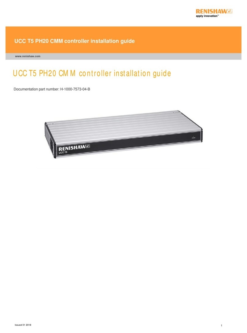
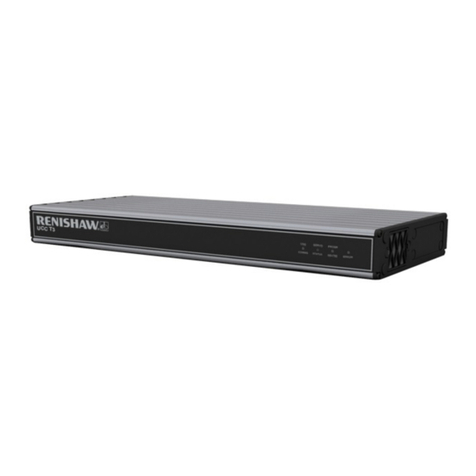
Renishaw
Renishaw UCC T3-2 User manual

Renishaw
Renishaw PHC10-3 PLUS User manual

Renishaw
Renishaw UCC MMI-2 User manual

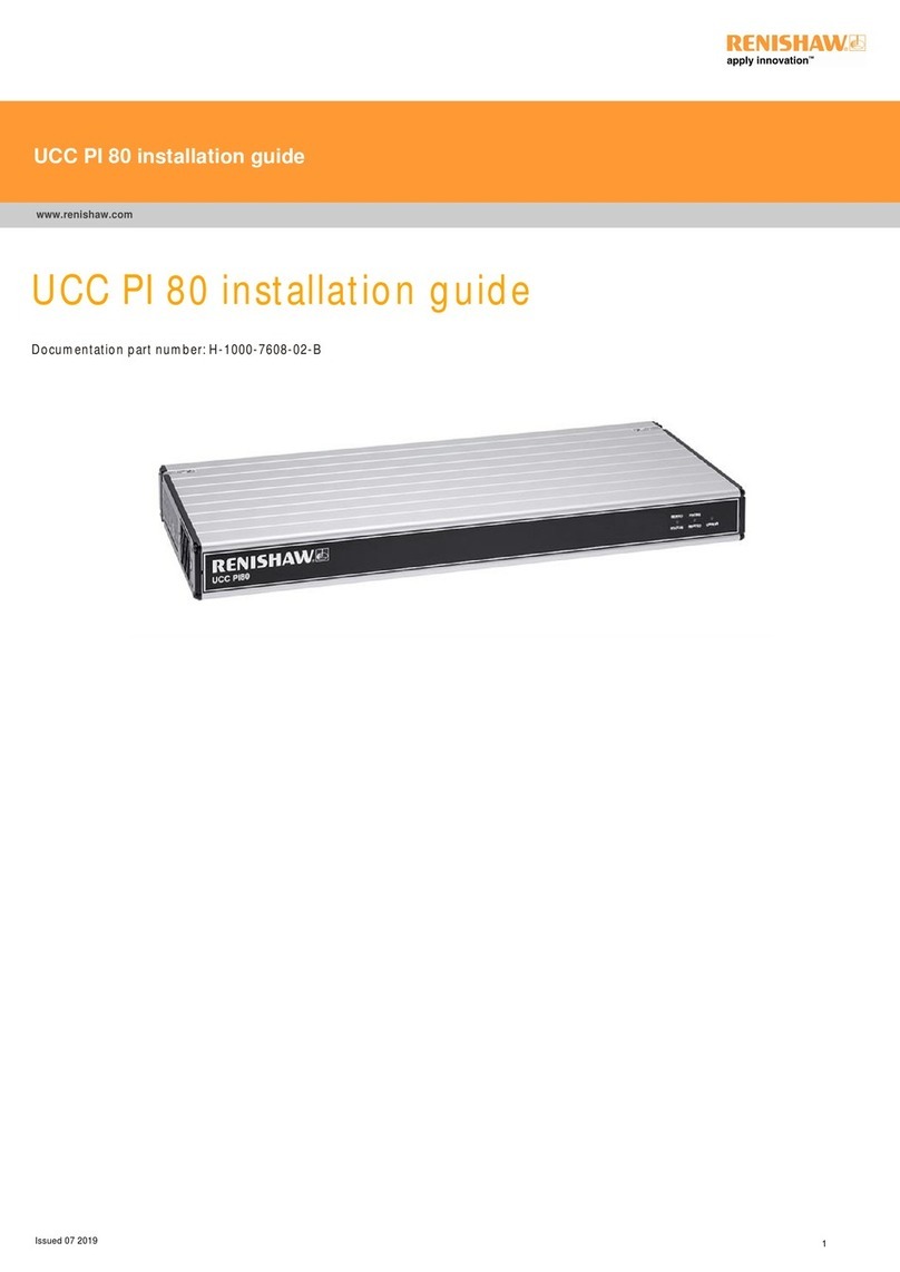
Renishaw
Renishaw UCC PI 80 User manual

Renishaw
Renishaw UCC T5 User manual

Renishaw
Renishaw UCC MMI User manual

Renishaw
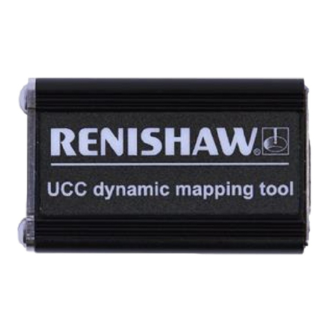
Renishaw UCC dynamic mapping tool User manual

Renishaw
Renishaw UCC1 User manual

Renishaw
Renishaw UCC T3 User manual

Renishaw
Renishaw PHC10-3 PLUS User manual