1.1
Before you begin
Before you begin
Disclaimer
RENISHAW HAS MADE CONSIDERABLE
EFFORTS TO ENSURE THE CONTENT OF THIS
DOCUMENT IS CORRECT AT THE DATE OF
PUBLICATION BUT MAKES NO WARRANTIES
OR REPRESENTATIONS REGARDING
THE CONTENT. RENISHAW EXCLUDES
LIABILITY, HOWSOEVER ARISING, FOR ANY
INACCURACIES IN THIS DOCUMENT.
Trade marks
RENISHAW and the probe symbol used in the
RENISHAW logo are registered trade marks of
Renishaw plc in the United Kingdom and other
countries. apply innovation and names and
designations of other Renishaw products and
technologies are trade marks of Renishaw plc or
its subsidiaries.
All other brand names and product names used
in this document are trade names, trade marks, or
registered trade marks of their respective owners.
Warranty
Equipment requiring attention under warranty
must be returned to your equipment supplier.
Unless otherwise specifically agreed in writing
between you and Renishaw, if you purchased
the equipment from a Renishaw company, the
warranty provisions contained in Renishaw’s
CONDITIONS OF SALE apply. You should consult
these conditions in order to find out the details
of your warranty but, in summary, the main
exclusions from the warranty are if the equipment
has been:
• neglected, mishandled or inappropriately used;
or
• modified or altered in any way except with the
prior written agreement of Renishaw.
If you purchased the equipment from any other
supplier, you should contact them to find out what
repairs are covered by their warranty.
Changes to equipment
Renishaw reserves the right to change equipment
specifications without notice.
CNC machines
CNC machine tools must always be operated by
fully trained personnel in accordance with the
manufacturer's instructions.
Care of the system components
Keep system components clean and treat with
care. Do not apply labels to the front of the
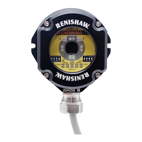
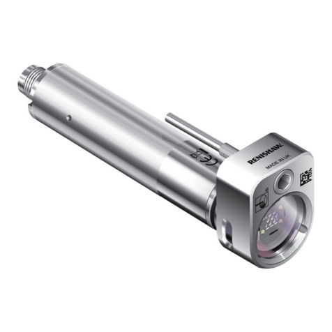
OMM-2C or otherwise obstruct the window.
