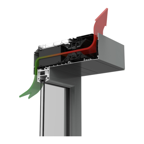
Invisivent®AIR & Invisivent®COMFORT
Montageanleitung
Assembly manual
1. Vorbereitung
➊Richten Sie die RENSON-Montagehilfen links und rechts am Fensterprofil aus.
➋Platzieren Sie den Invisivent AIR oder Invisivent COMFORT mit der Innenklappe nach oben in den Montagehilfen
und führen Sie den Invisivent gegen das Fensterprofil. Stellen Sie sicher, dass sowohl die Endkappen als auch das
Außenprofil perfekt in das Fensterprofil passen.
Erforderliche Utensilien
Erhältlich bei Renson
➊Bohr- und Schraubhilfe mit Sonderbohreinsatz
➋Schraubzwingen mit Montageblöcken
➌Kurze Schrauben für Aluminium (3,9 x 25 mm TX20)
➍Lange Schrauben für Aluminium (5,5 x 75 mm TX20)
➎Lange Schrauben für PVC/Holz (5,5 x 85 mm TX20)
ACHTUNG: Bei der Installation des Invisivent AIR/COMFORT
ist der Einsatz der RENSON-Montagehilfe und der Sonder-
schrauben zwingend erforderlich. Sollten Sie andere Bauteile
verwenden, erlischt jegliche Garantie. Der Einsatz der Schraub-
zwingen ist zwar nicht zwingend erforderlich, wird aber
dringend empfohlen.
Vom Kunden bereitzustellen
➏Standardbohrmaschine (1 oder 2)
➐Bohreinsatz Ø 3 mm und min. 120 mm lang
➑Bohreinsatz Ø 4,8 mm und min. 100 mm lang
Required materials
Available at Renson
➊Drilling and screwing tool with custom drill bit
➋Bar clamps with installation blocks
➌Short screws for aluminium (3.9 x 25 mm TX20)
➍Long screws for aluminium (5.5 x 75 mm TX20)
➎Long screws for PVC/wood (5.5 x 85 mm TX20)
ATTENTION: When installing the Invisivent
AIR/COMFORT, the use of the RENSON assembly
aid and custom screws is mandatory. Using other parts
will void any warranty. The use of bar clamps is not
mandatory, but strongly recommended.
To be provided by the customer
➏Standard drill (1 or 2)
➐Drill bit Ø 3 mm and min. 120 mm long
➑Drill bit Ø 4.8 mm and min. 100 mm long
1. Preparation
➊Align the left and right RENSON assembly aids on the window profile.
➋Insert the Invisivent AIR or Invisivent COMFORT into the assembly aids with the inner valve facing up and guide the
Invisivent against the window profile.
Make sure that both the end caps and the outer profile perfectly match the window profile.
2. Vordere Befestigung
NUR FÜR FENSTERPROFILE AUS ALUMINIUM
➊Das Aluminium-Außenprofil vom Invisivent AIR und Invisivent COMFORT ist oben mit Schraublöchern (mit blauen
Verschlusskappen) versehen.
Entfernen (und bewahren) Sie zuerst alle blauen Verschlusskappen mithilfe eines flachen Schraubendrehers oder der
mitgelieferten Lasche an der RENSON-Bohr- und Schraubhilfe.
➋Bohren Sie eine erste Schraubenposition mit der RENSON-Bohr- und Schraubhilfe vor.
Wählen Sie zunächst die Schraubenposition auf der äußerst linken oder äußerst rechten Seite aus.
➌Mit der RENSON-Bohr- und Schraubhilfe einschrauben. Verwenden Sie dafür den Sonderbohreinsatz und die
RENSON-Sonderschrauben (Typ 3,9 x 25 mm TX20).
Verwenden Sie nach Möglichkeit eine Standardbohrmaschine. Bei Bohrmaschinen mit Schiebesperrmechanismus
passt der Sonderbohreinsatz nicht direkt in die Maschine.
Verwenden Sie in diesen Fällen immer einen Bithalter.
➍Sobald der Flansch des Bohreinsatzes die Bohr- und Schraubhilfe berührt, befindet sich die Schraube an der richtigen
Stelle und auf der richtigen Tiefe im Aluminium-Außenprofil.
➎
Bohren und schrauben Sie dann alle dafür vorgesehenen Positionen ein. Fangen Sie mit der Schraubenposition am anderen
Ende (1) des Insivent AIR oder Invisivent COMFORT an. Bohren und schrauben Sie dann alle mittleren Positionen ein (2).
➏Setzen Sie die blauen Verschlusskappen wieder in jeder Schraubenöffnung auf.
2. Fixation at the front
ONLY FOR ALUMINIUM WINDOW PROFILES
➊The aluminium outer profile of the Invisivent AIR & Invisivent COMFORT has holes at the top for screws (with blue
sealing caps).
First remove (and store) all blue sealing caps using a flat screwdriver or the tab provided on the RENSON drilling
and screwing tool.
➋Drill a first screw position using the RENSON drilling and screwing tool.
First, select the far left or far right screw position.
➌Screw into place using the RENSON drilling and screwing tool.
Use the custom drill bit and the RENSON custom screws (type 3.9 x 25 mm TX20).
If possible, use a standard drill. If the drill has a sliding lock mechanism, the custom drill bit will not directly fit.
Always use a bit holder in these cases.
➍As soon as the flange of the drill bit touches the drilling and screwing tool, the screw is positioned in the right place
and at the right depth in the aluminium outer profile.
➎Then drill and screw into all the positions provided for this purpose. Start with the screw position on the other end (1)
of the Invisivent AIR or Invisivent COMFORT, then drill and screw into all middle positions (2).
➏Put the blue sealing caps back into each screw opening.
➋
➋ ➍ ➏➌ ➎
➊
➊
Ø3mm
min.120mm
AUSSENSEITE
OUTSIDE
INNENSEITE
INSIDE
© L0000229 06/20 DE/EN
➊
➌
➍
➎
➏
➐
➑
3. Befestigung durch den PVC-Körper
FÜR ALLE FENSTERPROFILE (PVC, Aluminium, Holz)
➊Auf dem PVC-Gehäuse sind die Schraubzonen angegeben, in denen Sie vorbohren/schrauben können, um den
Invisivent am Fensterprofil zu befestigen.
➋Eine zusätzliche Schraubenposition wurde in den Innen- und Mittelendkappen hinzugefügt, insbesondere für
kürzere Invisivents oder Invisivents, bei denen die ersten verfügbaren Schraubenzonen zu weit von den Endkappen
entfernt sind. Diese zusätzlichen Schraubzonen gewährleisten auch unter diesen Bedingungen eine feste und stabile
Verankerung des Invisivent am Fensterprofil.
ACHTUNG: Bei der Verankerung durch die Endkappen empfehlen wir die Verwendung von Bohrern
mit den folgenden Bohrdurchmessern:
- Aluminiumfenster mit Ø 4,2 mm vorbohren (üblicherweise in den Presseckwinkeln)
- PVC-Fenster mit Ø 4,5 mm vorbohren (ohne Stahlverstärkung)
Je nach Art des Fensterprofils können die oben genannten Bohrungsdurchmesser variieren.
➌Für jedes Fensterprofil kann eine passende Schraubenposition gewählt werden, damit nicht in die thermische
Unterbrechung des Fensterprofils geschraubt werden muss.
Bei PVC-Fenstern muss immer in das Stahlprofil im Fensterprofil geschraubt werden.
Bei PVC- oder Holzfenstern kann der Invisivent AIR oder Invisivent COMFORT optional auch vorne befestigt werden
(siehe „2. Vordere Befestigung“).
Prüfen Sie bei tieferen PVC-Fenstern immer, ob es möglich ist, “abwechselnd” zu verankern. Dies
erhöht die Stabilität während der Installation. Bei der Verankerung durch den PVC-Körper des
Invisivent AIR / COMFORT schrauben Sie zunächst so weit wie möglich in der Außenseite (in der
Verstärkung) des Fensterprofils und anschließend so weit wie möglich in der Innenseite.
➍Bohren Sie die erste Schraubenposition vor.
Wählen Sie dazu zunächst die Schraubenposition auf der äußerst linken oder äußerst rechten Seite aus.
➎Festschrauben. Verwenden Sie dafür die RENSON-Sonderschrauben (Typ 5,5 x 75 mm TX20 für Aluminiumprofile
und Typ 5,5 x 85 mm TX20 für PVC- oder Holzprofile). Verwenden Sie nach Möglichkeit eine Standardbohrmaschine
anstatt einer Bohrmaschine mit Schiebesperrmechanismus.
➏
Bohren und schrauben Sie dann alle dafür vorgesehenen Positionen ein. Fangen Sie mit der Schraubenposition am anderen
Ende (1) des Invisivent AIR oder Invisivent COMFORT an. Bohren und schrauben Sie dann alle mittleren Positionen ein (2).
➐Überprüfen Sie nach der Installation, ob sich die Fensterlüftung perfekt luftdicht an die Fensterkonturen anschließt.
Lösen Sie danach die Montagehilfen.
3. Fixation through the PVC body
FOR ALL WINDOW PROFILES (PVC, aluminium, wood)
➊Indications of the screw zones are made on the PVC body, where the Invisivent can be pre-drilled/screwed in order
to secure it to the window profile.
➋We included an additional screw position in the inner and middle end caps, especially for shorter Invisivents or
Invisivents where the first available screw zones are too far from the end caps. These additional screw zones ensure a
firm and stable anchorage of the Invisivent to the window profile even under these conditions.
ATTENTION: When anchoring through the end caps, we recommend using drill bits with the
following drilling diameters:
- Use Ø 4.2 mm for pre-drilling through aluminium windows (usually in the crimp corner cleats)
- Use Ø 4.5 mm for pre-drilling through PVC windows (no steel reinforcement)
Depending on the type of window profile, the above drilling diameters may vary.
➌A suitable screw position can be selected for each window profile so that it is not necessary to screw into the thermal
bridge of the window profile.
In the case of PVC windows, the steel reinforcement must always be screwed into the window profile.
In the case of PVC or wooden windows, the Invisivent AIR or Invisivent COMFORT can also be optionally fixed at the
front (see ‘2. Fixation at the front’).
Always check for deeper PVC windows whether it is possible to anchor them ‘alternately’. This
improves stability during installation. When anchoring through the PVC body of the Invisivent AIR /
COMFORT, make sure you first screw as much as possible to the outside (in the reinforcement) of the
window profile and then as much as possible to the inside.
➍Pre-drill a first screw position.
First, select the far left or far right screw position.
➎Screw into place. Use the RENSON custom screws (Type 5.5 x 75 mm TX20 for aluminium profiles and Type 5.5
x 85 mm TX20 for PVC or wood profiles). If possible, use a standard drill instead of a drill with a sliding lock
mechanism.
➏Then drill and screw into all the positions provided for this purpose. Start with the screw position on the other end (1)
of the Invisivent AIR or Invisivent COMFORT, then drill and screw into all middle positions (2).
➐Following the installation, check whether the window and the window vent are hermetically sealed.
Next, remove the assembly aids.
➋
➋
➌➊ ➎➍
➏
Ø4,8mm
min.100mm
✕➐
➋
Renson®Headquarters
Maalbeekstraat 10 • IZ 2 Vijverdam • B-8790 Waregem • Belgium
Tel. +32 56 30 30 00 • info@renson.be • www.renson.eu
