Rentech Jaguar 1.2K User manual

USER MANUAL
JAGUAR BATTERY BOX
1.2kVA / 900W
2.4kVA / 1600W
sales@powerprovider.co.za
www.powerprovider.co.za

Table of Contents
1. Introduction ...................................................................................................................................................1
2. Important Safety Warning (SAVE THESE INSTRUCTIONS)......................................................................1
3. Product Overview .........................................................................................................................................3
4. Installation .....................................................................................................................................................3
5. Operation .......................................................................................................................................................5
6. Trouble Shooting ........................................................................................................................................10
7. Specifications .............................................................................................................................................11

1
1. Introduction
Thank you for purchasing this inverter. This simple inverter is designed to power your home appliances or
precious 3C electronics. It also can handle motor-type loads with high surge power such as vacuums, small
freezers, or drills.
This manual is for qualified personnel. The tasks described in this manual may be performed by qualified
personnel only.
2. Important Safety Warning (SAVE THESE INSTRUCTIONS)
Before using the inverter, please read all instructions and cautionary markings on the unit, this
manual and the batteries.
General Precaution-
CAUTION! The unit is designed for indoor use. Do not expose this unit to rain, snow or liquids of any type.
CAUTION! To reduce risk of injury, only use qualified batteries from qualified distributors or manufacturers.
Any unqualified batteries may cause damage and injury. Do NOT use old or overdue batteries. Please check the
battery type and date code before installation to avoid damage and injury.
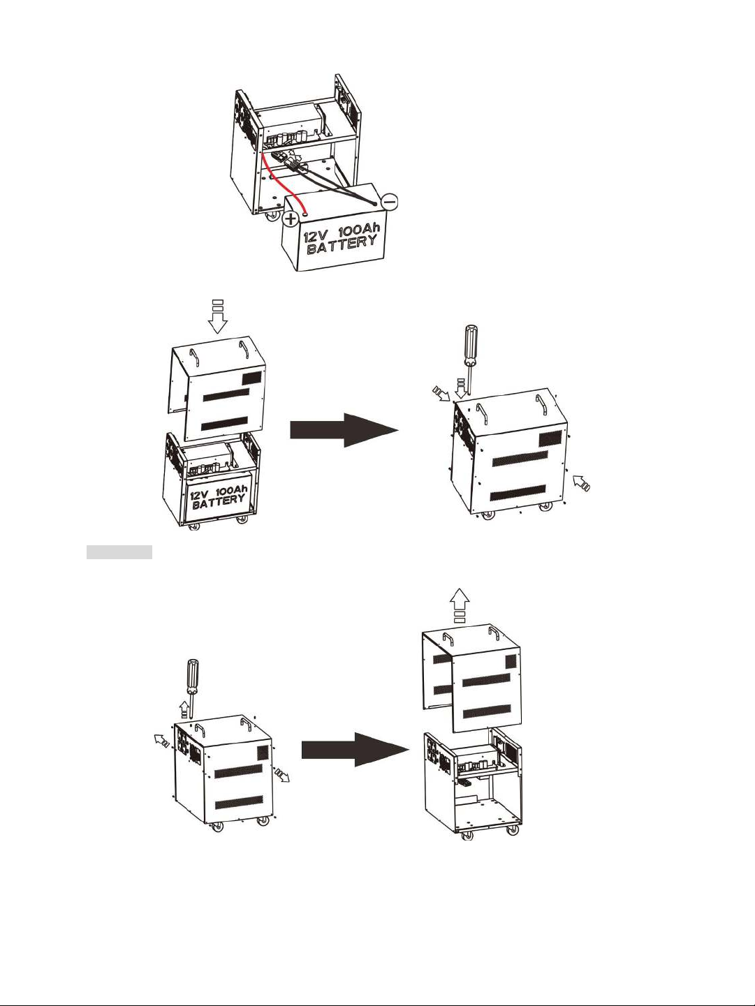
CAUTION! Authorized service personnel should reduce the risk of electrical shock by disconnecting AC, DC and
battery power from the inverter before attempting any maintenance or cleaning or working on any circuits
connected to the inverter. Turning off controls will not reduce this risk. Internal capacitors can remain charged
for 5 minutes after disconnecting all sources of power.
CAUTION! Do not disassemble this inverter yourself. It contains no user-serviceable parts. Attempt to service
this inverter yourself may cause a risk of electrical shock or fire and will void the warranty from the
Manufacturer.
CAUTION! To avoid a risk of fire and electric shock, make sure that existing wiring is in good condition and that
the wire is not undersized. Do not operate the Inverter with damaged or substandard wiring.
CAUTION! To reduce risk of fire hazard, do not cover or obstruct the cooling fan.
CAUTION! Do not operate the inverter if it has received a sharp blow, been dropped, or otherwise damaged in
any way. If the inverter is damaged, called for an RMA (Return Material Authorization).
WARNING: There are no user-replaceable parts inside of the inverter. Do not attempt to service the unit
yourself.
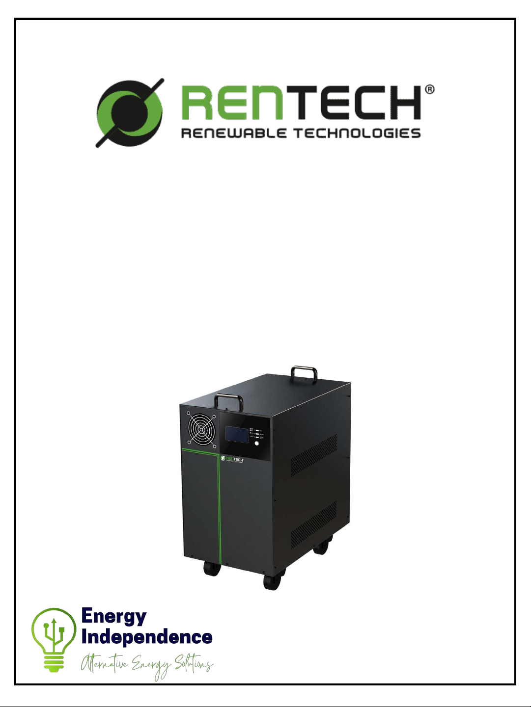
WARNING! It's very important for system safety and efficient operation to use appropriate external battery
cable. To reduce risk of injury, external battery cables should be UL certified and rated for 105°C or higher. And
do not use copper cables less than 6AWG or 10AWG*2.
CAUTION! Do not disassemble the inverter. Contact with the qualified service center when service or repair is
required.
WARNING! Provide ventilation to outdoors from the battery compartment. The battery enclosure should be
designed to prevent accumulation and concentration of hydrogen gas at the top of the compartment.
CAUTION! Use insulated tools to reduce the chance of short-circuit when installing or working with the inverter,
the batteries, or other equipments attached to this unit.
CAUTION! For battery installation and maintenance, read the battery manufacturer's installation and
maintenance instructions prior to operating.
Personnel Precaution -
CAUTION! Careful to reduce the risk or dropping a metal tool on the batteries. It could spark or short circuit the
batteries and could cause an explosion.
CAUTION! Remove personal metal items such as rings, bracelets, necklaces, and watches when working with
batteries. Batteries can produce a short circuit current high enough to make metal melt, and could cause severe
burns.
CAUTION! Avoid touching eyes while working near batteries.
CAUTION! Have plenty of fresh water and soap nearby in case battery acid contacts skin, clothing, or eyes.
Conventions used:
WARNING! Warnings identify conditions or practices that could result in personal injury;
CAUTION! Caution identify conditions or practices that could result in damaged to the unit or other
equipment connected.

2
CAUTION! NEVER smoke or allow a spark or flame in vicinity of a battery.
CAUTION! If a remote or automatic generator start system is used, disable the automatic starting circuit or
disconnect the generator to prevent accident during servicing.

3
3. Product Overview
1.2K 2.4K
4. Installation
NOTE: Before installation, please inspect the unit. Be sure that nothing inside the package is damaged.
Connect to Utility and Charge
Plug in the AC input cord to the wall outlet. The unit will automatically charge the internal battery even though
the unit is off.
Connect to Battery Pack
1.2k Model
Follow below steps to connect battery pack.
Step 1: Take out top case by removing screws as shown below chart.
1. Power switch
2. Status indicator
3. Charging indicator
4. Fault indicator
5. Function buttons
(Please see the Operation section for the details)
6. LCD display
7. AC input
8. AC output receptacles
9. Input circuit breaker
10. DC fuse

4
Step 2: Follow below chart to connect battery pack.
Step 3: Insert battery pack inside of cabinet. Assemble top case to original position.
2.4k Model
Follow below steps to connect battery pack.
Step 1: Ta ke out top case by removing screws as shown below chart.

5
Step 2: Follow below chart to connect battery pack.
Step 3: Insert two battery packs inside of cabinet. Assemble top case to original position.
5. Operation
Power On/Off
Once the inverter has been properly installed, press the power switch to turn on the unit. The unit will work
automatically in line mode or inverter mode according to input utility power's status. When press the power
switch again, the unit will be turned off.
LED Indicators, Function Keys & Audible Alarms
There are three indicators in the front panel of the unit.
LED Indicator
Messages
Green
Solid On
Output is available in bypass mode
Flashing
Output is powered by battery in inverter mode
Green
Solid On
Battery is not charging.
Flashing
Battery is charging.
Red
Solid On
Fault mode
Flashing
battery low or overload warning
Function Keys
Function Key
Description
ESC
To exit setting mode
SELECT
To go to next selection
ENTER
To confirm the selection in setting mode or enter setting mode

6
Audible Alarms
Buzzer Audible Alarm
Messages
Inverter Mode (Low-battery Voltage)
Buzzing every 1 seconds
110% overload warning
Buzzing every 0.5 second
Overcharge
Buzzing continuously
Fault mode
Buzzing continuously
LCD Display
Display
Function
Input source information
Indicates the AC input
Indicates input voltage and battery voltage.
Configuration Program and Fault Information
Indicates the setting programs.
Indicates the warning and fault codes.
Warning: Flashing with warning code
Fault: Lighting with fault code
Output Information
Indicates the output voltage, load percent, load in Watt and main board firmware
version.
Battery Information
Indicates the Battery level by 0-24%, 25-49%, 50-74% and 75-100% in battery mode,
charging status in line mode.
In AC mode, it will present battery charging status.
Status
Battery voltage
LCD Display
Constant
Current mode /
Constant
Voltage mode
< 11Vdc/pcs
4 bars will flash in turns.
11Vdc ~ 11.5Vdc/pcs
Bottom bar will be on and the other three
bars will flash in turns.
11.5Vdc ~ 12.5Vdc/pcs
Bottom two bars will be on and the other
two bars will flash in turns.
> 12.5Vdc/pcs
Bottom three bars will be on and the top
bar will flash.
Floating mode. Batteries are fully charged.
4 bars will be on.
In battery mode, it will present battery capacity.
Battery Voltage
LCD Display
< 11Vdc/pcs
11.0Vdc ~ 11.5Vdc/pcs
11.5Vdc ~ 12.5Vdc/pcs
> 12.5Vdc/pcs
Load Information
Indicates overload.
Indicates the load level by 0-24%, 25-49%, 50-74%, and 75-100%.
0%~24%
25%~49%
50%~74%
75%~100%

7
Mode operation information
Indicates unit connects to the mains.
Indicates load is supplied by utility power.
Indicates the utility charger circuit is working.
Indicates the DC/AC inverter circuit is working.
LCD Setting
After pressing and holding ENTER button for 3 seconds, the unit will enter setting mode. Press “SELECT” button
to select setting programs. And then, press “ENTER” button to confirm the selection or ESC button to exit.
Setting Programs
Program
Description
Selectable option
00
Exit setting mode
Escape
01
AC input voltage
range
Wide (default)
If selected, acceptable AC input voltage range will be
within 90-280VAC.
Narrow
If selected, acceptable AC input voltage range will be
within 170-280VAC.
02
Battery type
AGM(Default)
Flooded
User-defined
03
Max AC charging
current
20A(default)
10A
04
Bulk charging (C.V
voltage)voltage
12V model default setting: 14.1V
24V model default setting: 28.2V
If self-defined is selected in program 02, this program can be set up. Setting
range is from 13.0V to 14.6V for 12Vdc model and increment of each click is
0.1V. Setting range is from 26.0V to 29.2V for 24Vdc model and increment of
each click is 0.2V.
05
Floating charging
voltage
12V model default setting: 13.5V

8
24V model default setting: 27.0V
If self-defined is selected in program 02, this program can be set up. Setting
range is from 13.0V to 14.6V for 12Vdc model and increment of each click is
0.1V. Setting range is from 26.0V to 29.2V for 24Vdc model and increment of
each click is 0.2V.
06
Low DC cut-off
voltage
1.2K default setting: 9.9V
2.4K default setting: 19.8V
Setting range is from 9.9V to 12.0V for 1.2K model and increment of each click
is 0.1V Setting range is from 19.8V to 24.0V for 2.4K model and increment of
each click is 0.2V. Low DC cut-off voltage will be fixed to setting value no
matter what percentage of load is connected.
Display Setting
The LCD display information will be switched in turns by pressing “SCROLL” key. The selectable information is
switched as below order: input voltage, battery voltage, output voltage, load percentage, load in Watt and main
CPU Version.
Selectable
information
LCD display
Selectable
information
LCD display
Input voltage/Output
voltage
(Default Display
Screen)
Input Voltage=230V,
output voltage=230V
Main CPU
version
checking
Main CPU version 00001.01
Battery voltage/Load
percentage
Load percent=70%
Battery
voltage/Load
in Watt
When load is lower than 1kW,
load in W will present xxxW like
below chart.
When load is larger than 1kW
(≧1KW), load in W will present
x.xkW like below chart.

9
Operating Mode Description
Operation mode
Description
LCD display
Standby mode
Note:
*Standby mode: The inverter is
not turned on yet but at this
time, the inverter can charge
battery with AC bypass output.
Utility input bypass to
output, charger
available, LCD backlight
is off
Charging by utility.
Line Mode
The unit will provide
output power from the
mains. It will also
charge the battery at
line mode.
Charging by utility.
Battery Mode
The unit will provide
output power from
battery.
Power from battery only.
Fault Reference Code
Fault Code
Fault Event
Icon on
Fault Code
Fault Event
Icon on
00
Output short circuit
05
Fan locked
01
Over load time out
06
Over temperature
03
Output voltage too
high
08
Over charge
Warning Indicator
Warning Code
Warning Event
Icon flashing
01
Over load
02
Battery low

10
6. Trouble Shooting
Use the table below to solve minor problems.
Problem
LCD/LED/Buzzer
Explanation / Possible cause
What to do
When power fails,
the backup time is
shorten.
Battery low alarm
issue quickly.
Battery voltage is too low.
Charge the unit at least 8
hours.
Battery capacity is not full even
after charge the unit for at least 8
hours.
Check the date code of the
battery. If the batteries are
too old, replace the batteries.
Mains exist but the
unit works in
battery mode.
Input voltage is
displayed as 0 on the
LCD and green LED is
flashing.
Input protector is tripped
Check if AC breaker is tripped
and AC wiring is connected
well.
Green LED is flashing.
Insufficient quality of AC power.
(Shore or Generator)
1. Check if AC wires are too
thin and/or too long.
2. Check if generator (if
applied) is working well or if
input voltage range setting is
correct. (NarrowÆWide)
No LED display on
the front panel
when the utility
power is normal.
No LED display.
Battery is not connected well.
Check the external battery
cable and terminal. Make sure
all the battery connections to
the unit are all correct.
Battery defect.
Replace the batteries.
Buzzer beeps
continuously and
red LED is on.
Fault code 00
Output short circuited.
Check if wiring is connected
well and remove abnormal
load.
Fault code 01
Overload error. The inverter is
overload 110% and time is up.
Reduce the connected load by
switching off some
equipment.
Fault code 03
Output voltage too high
Return to repair center.
Fault code 05
Fan fault
Replace the fan.
Fault code 06
Internal temperature of inverter
component is over 100°C.
Check whether the air flow of
the unit is blocked or whether
the ambient temperature is
too high.
Fault code 08
Battery is over-charged.
Return to repair center.
The battery voltage is too high.
Check if spec and quantity of
batteries are meet
requirements.
If there is any abnormal situations occur, which doesn't list above, please call the service people immediately
for professional examine.

11
7. Specifications
MODEL
1.2K
2.4K
CAPACITY
1200VA/900W
2400VA/1600W
INPUT
Voltage
220-240 VAC
Voltage Range
90-280 VAC
Nominal Operating Frequency
50/60Hz
Maximum Input Current
10A
13A
OUTPUT
Nominal Output Voltage
220-240 VAC
Voltage Regulation (Batt. Mode)
+/-10%
Output Frequency Range
50/60Hz
Nominal Output Current
5.2A
10.4A
Inrush Current
10A
13A
Maximum Output Fault Current
6.9A
13.6A
Transfer Time
20 ms typical
Waveform
Simulated Sine Wave
BATTERY
Battery Type and Numbers
12 V 100Ah x 1
12 V 100Ah x 2
Maximum Battery Discharging
Current
76A
76A
Floating Charge Voltage
13.7 VDC ±0.5 VDC
27.4 VDC ±1 VDC
Maximum AC Charging Current
10 A or 20 A
10 A or 20 A
PHYSICAL
Dimension (DxWxH) mm
393*250*459
345*400*450
Net Weight (kgs)
40.5
75.8
Protective Class
I
Ingress Protection Rating
IP20
ENVIRONMENT
Humidity
0 ~ 90% RH (No condensing)
Operating Temperature
0 to 55°C
Altitude
0 ~ 1000 m

Other manuals for Jaguar 1.2K
1
This manual suits for next models
1
Table of contents
Other Rentech Inverter manuals
Popular Inverter manuals by other brands

Lenze
Lenze i750 Translation of the original operating instructions

Mitsubishi Electric
Mitsubishi Electric fr-e720-008 instruction manual

Toshiba
Toshiba BACnet BCN001Z Function manual

Dressler
Dressler 13150 400 V user manual

Omron
Omron CIMR-E7Z - quick guide

Toshiba
Toshiba TOSVERT VF-S15 series Quick start manual