Rescue 42 CRD User manual

P.O. Box 1242 • Chico, CA 95927 • (888) 427-3728
1 of 2
32018-A
CRD
™
for FirstNet
®
|
Quick Start Guide: Vehicle Loading
Vehicle Loading
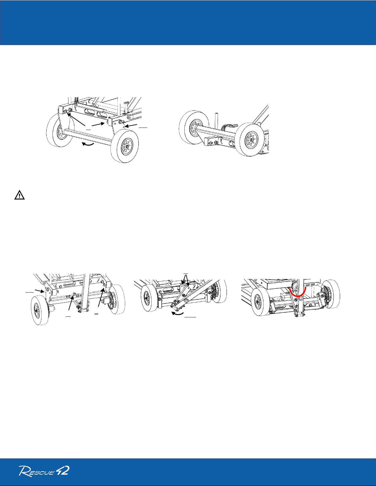
1. Position the vehicle’s tow hitch over solid, level ground.
2. Remove the Hitch Adapter from the Chassis Bed and insert the Receiver Tongue into the
hitch of vehicle. Secure with the Anti-Rattle Hitch Pin ensuring that the threaded block is on
inserted side.
3. Set the Height Adjustment of the Hitch Adapter to highest setting as available based on the
vehicle’s receiver clearance measurement for maximum ground clearance.
4. Pull the Hitch Adapter’s Mounting Box up & away from the vehicle to seat the
PitchLok Pins in the LOAD position.
5. Raise the CRD by rotating the Crank Handle CLOCKWISE to elevate the Mounting
Pin above the Hitch Adapter. Roll into position with the Mounting Pin above the
Mounting Box Receiver Tube.
6. Turn the Crank Handle COUNTER-CLOCKWISE to lower the Mounting Pin into
the Hitch Adapter until the Mounting Tabs drop and lock into their respective holes.
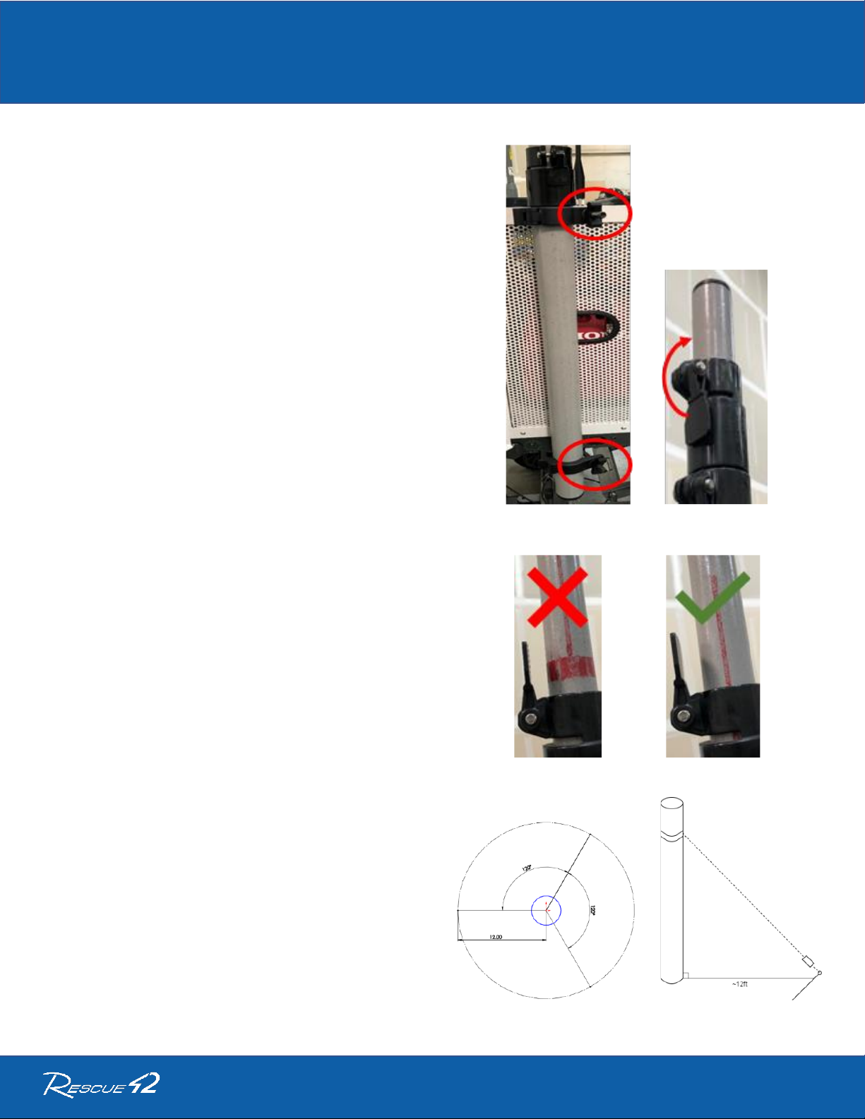
7. Continue lowering until the weight begins to transfer to the vehicle’s suspension.
STOP turning the handle. Give the Unit a firm push towards the vehicle. The
PitchLok Pins will slide down into the TRANSPORT position.
8. Connect the Runner’s Chassis 4-pin connector to the vehicle’s 4-pin receiver and
test for proper operation of the Stop, Turn, and Taillights.
9. After securing the unit into the TRANSPORT Position, continue raising the Lower
Frame until the Mounting Box locks on the tabs of the Lower Frame, then a ¼ to ½
a turn more to add compression securing it to the Hitch Adapter.
Receiver
Clearance
Measurement
1
2
3
#
Clearance
1
24”+
2
20-24”
3
12-20”
LOAD
TRANSPORT
TAB

P.O. Box 1242 • Chico, CA 95927 • (888) 427-3728
2 of 2
32018-A
CRD
™
for FirstNet
®
|
Quick Start Guide: Vehicle Loading
10. Remove Leg Pins (A) from both sides of the Tail Axle assembly.
11. Rotate the Tail Axle upwards.
12. Reinsert Leg Pins into the UP-position holes.
Exercise caution to not pinch the Brake Lines.
13. Remove the Steering Lock Pin (A) and both Leg Pins (B).
14. Rotate the axle half-way up, then rotate the steering handle counterclockwise 180°.
15. Align the steering link and lock tab holes (C) and insert the steering lock pin (A).
16. Rotate the wheels all the way into the UP position.
17. Reinsert both leg pins (B) into UP position holes.
18. Use the Red Safety Lanyard to secure the handle.
19. Verify Chassis lights are fully functional before traveling.
A
UP
A
B
UP
C
180°

CRD
™
for FirstNet
®
|
Quick Start Guide: Vehicle Unloading
P.O. Box 1242 • Chico, CA 95927 • (888) 427-3728
1 of 2
32019-A
Vehicle Unloading
Position the vehicle (and the mounted SatRunner) over firm,
level ground.
Disconnect and stow the 4-pin light connector.
Set the SatRunner’s Parking Brake.
Remove both leg pins (A) from the UP-position holes.
[see Figure 1]
Rotate the Tail Axle downwards.
Insert both leg pins (A) locking the Tail Axle into the DOWN
position holes. [see Figure 2]
Unclip the Red Safety Lanyard securing the Pull Handle.
Remove both leg pins (B) and steering lock pin (C).
[see Figure 3]
Rotate the Steering Axle downwards approximately halfway
and then rotate the steering handle clockwise 180°.
[see Figure 4]
Figure 1
Figure 2
Figure 3
Figure 4
A
A
DOWN
C
B
180°

CRD
™
for FirstNet
®
|
Quick Start Guide: Vehicle Unloading
P.O. Box 1242 • Chico, CA 95927 • (888) 427-3728
2 of 2
32019-A
Align the steering link and tie rod holes (D) and insert the steering
lock pin (C). [see Figure 5]
Insert both leg pins (B) into DOWN position holes. [see Figure 6]
Turn the Crank Handle CLOCKWISE, to lower the wheels, until
they meet the ground.
a. Once the wheels meet the ground, there will be resistance in
the Crank Handle as the weight shifts from the vehicle to the
SatRunner.
b. Continue turning the Crank Handle CLOCKWISE, until the
PitchLok Pins pop loose and the Mounting Pin comes out of the
Mounting Box.
Continue elevating until the Mounting Pin is clear of the Mounting
Box, unlock the parking brake and move the unit away from the
vehicle.
If the vehicle needs to leave, remove Hitch Adapter from the
vehicle and store it in the bed on the Lower Frame.
Be sure the unit is clear of any obstruction and then turn the
Crank Handle COUNTER-CLOCKWISE to lower the Upper
Frame onto the Lower Frame.
Roll the SatRunner to the desired location for operation.
Figure 5
Figure 6
Figure 7
C
D
DOWN
B

P.O. Box 1242 •Chico, CA 95927 • (888) 427-3728
1 of 2
32022-A
CRD™for FirstNet®| Quick Start Guide: Mast
Deploying the Mast
1. Make sure the two Mast Mounting Clamps are tight.
[see Figure 1]
2. If guying mast, do so now.
3. Securely attach antennas to mast top.
4. Undo the top mast lock and use your hands to extend the
smallest diameter pole. [see Figure 2]
5. Pivot the locking lever back down to secure the extended
section of the mast.
6. Repeat step 3 for the rest of the sections, as needed.
a. DO NOT overextend the mast poles!
b. There are red lines to show you are close to
the end of the pole.
c. The Mast should not ever be extended to a
point that the Red Ring is showing on the
pole. [see Figure 3] The red ring must be below
the cutout for the clamp. [see Figure 4]
Guying the Mast
7. Retrieve the Mast Guy Wire Stakes.
8. Find three spots approximately 12’ from the Mast. They
should be roughly 120° apart. [see Figure 5]
9. Drive the stakes into the ground at a ~45° angle, toward
the Mast. [see Figure 6]
10. Obtain the three Guy Lines from the Accessory Bag.
Figure 1 Figure 2
Figure 3 Figure 4
Figure 5 Figure 6

P.O. Box 1242 •Chico, CA 95927 • (888) 427-3728
2 of 2
32022-A
CRD™for FirstNet®| Quick Start Guide: Mast
11. Securely fasten Pear Clips (B) to the three points
(A) on the Mast Guy Ring. [see Figure 7]
12. Slide Mast Guy Ring onto mast. Guy Ring will sit
at the base of the smallest diameter tube section.
13. Hook a Tensioner Strap (C) to each Stake using a
Lark’s head and hook the Tensioner to the open
loop. [see Figure 8]
14. Leave the line with enough slack to fully extend
the mast.
15. Extend the Mast to desired height.
16. Tension all three Guy Lines.
Guy Line Tensioners
The guy line tensioners allow quick easy to guy the
mast. These are single direction pull with a release
cam. [see Figure 9]
Feed guy line in direction of arrow of first image. [see
Figure 10] Pull guy line down and into cam lock to
tension as in second image.
To release tension, push plunger (C) in direction of
arrow.
Guy Rope Knot
The recommended knot for guy ropes is the Figure
Eight on a Bight. [see Figure 11] Loop Pear Clip
through to point (1).
Figure 7 Figure 8
Figure 9
Figure 10
Figure 11
A
A
B
C

P.O. Box 1242 •Chico, CA 95927 • (888) 427-3728
1 of 1
32023-A
CRD™for FirstNet®| Quick Start Guide: Stabilizers
Stabilizing
Remove the orange and red stabilizer cables from storage drawer.
Remove Red Safety Lanyards securing stabilizer legs and rotate legs to
the ground. Raise chassis with Crank Handle approximately 12”.
Anchor orange cable to key slots on the long Lower Frame rails, [see
Figure 1]. Orange cable mount keyholes are on the bottom of the Lower
Frame below Cable Slot label. Anchor opposite end to slot in stabilizer
leg. Repeat for remaining orange cables.
Lower chassis Pull Handle to ground before connecting red cables.
Anchor red cable to key slot on the lower frame short end rail and cross
over to opposing leg, [see Figure 2]. Cable mount keyways are on the
face of the short rails. Repeat for other red cables.
Lower the chassis with Crank Handle by rotating counterclockwise. This
will force weight onto legs and slide them outwards until cables are
taught, [see Figure 3]. Ensure feet slide smoothly and are not caught on a
rough surface or obstacle. Lower chassis enough to stabilize where the
wheels are not bearing any weight.
If CRD is not close to level due to uneven ground, reverse process to
take weight off the stabilizers and extend leveling feet on the downhill
side [see Figure 4]. Retighten the cables.
Rotate chassis handle upright and secure with Red Safety Lanyard.
Figure 1
Figure 2
Figure 3
Figure 4
KEY HOLE

P.O. Box 1242 • Chico, CA 95927 • (888) 427-3728
1 of 1
32031-A
CRD™for FirstNet®| Quick Start Guide: Networking AvL Ku
Network Map

P.O. Box 1242 •Chico, CA 95927 • (888) 427-3728
1 of 1
32031-A
CRD™for FirstNet®| Quick Start Guide: Troubleshooting
Symptom
Possible Cause
Solution
System is not turning on
Battery is dead
Charge the system
Circuit breaker disconnected
Reconnect battery circuit breaker
Master power control fuse blown
Find reason for blown fuse and repair
then replace fuse
System not charging from AC
AC Source no good
Connect to known good AC source
Shore/Gen switch does not match input plug
Set to appropriate AC input source
PCM Input Power Source switch not set to AC
On PCM move Input Power Source
switch to AC
Circuit breaker in open state
Flip AC inlet circuit breaker switch to On.
Satellite not acquiring heading
GPS signal obstructed
Move to area with clear view of sky.
System alarm activated
Loss of AC power with Input Power Source
set to AC
If attempting to run from AC source, see
system not charging from AC.
If running from onboard battery set
Input Power Source switch to DC.
Battery Monitor alarm condition
Check battery monitor for alarm fault.
Most commonly a low charge or voltage.
Charge the system.

P.O. Box 1242 •Chico, CA 95927 • (888) 427-3728
1 of 1
32030-A
CRD™for FirstNet®| Quick Start Guide: Initial Setup
Initial Setup
Turn on all circuit breakers located on the rear of the PCM. (1 –4)
[see Figure 1]
a. For 1 and 2 rotate the yellow lever upwards until
clicked into position.
b. For 3 and 4 flip the toggle switches up.
Connect Shore AC power to Shore AC Inlet (1) and rotate Power
Inlet Selection Switch to Shore (2). [see Figure 2]
Set Source Power Switch to AC on front of the PCM.
[see Figure 3]
Charge unit completely until Battery Monitor synchronizes to the
full state (approximately 1 hour).
Compensate the compass as necessary per manufacturer
specifications.
The Cradlepoint router is preconfigured for the CRD. If other
networking changes are required consult an IT professional.
Perform initial setup on generator. Follow manufacturer
specifications. This includes, but not limited to:
a. Fill with oil
b. Fill with gasoline
c. Check for leaks
Figure 1
Figure 2
Figure 3
1
2
3
4
1
2
1
Table of contents