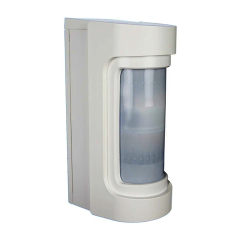
resideo Honeywell Home PROOUTMV Assembly instructions

PROOUTMV
Outdoor Motion Viewer
Installation and Setup Guide
The PROOUTMV is a battery-powered, wireless outdoor motion
detector with a built-in video camera is intended for use with
ProSeries Control Panels. The detector is powered by three
C123A lithium batteries that provide up to 4 years of battery life
(typical use).
The detector can be mounted directly on a wall or with an
optional mounting bracket.
NOTE:Installation shall be done in accordance with the
National Electrical Code, NFPA 70.
FEATURES
•No wiring or remote power required. Fully portable battery powered camera allows for flexibility in selecting locations
•Provides video stream and live video viewing functionality
•The module features an advance triggering algorithm to minimize the possibility of false alarm activations.
•AES Encrypted Wireless technology provides optimum signal integrity and security
•CMOS camera sensor with a wide angle 90° lens (horizontal field of view)
•Night vision (up to 16 feet,5 meters) with one white LED
•Fresnel lens motion detection: 39.73 ft (12m), and 90° detection pattern
•
Camera sends color video
ENROLLMENT
You must enroll the detector in the Control Panel.
Enrollment and RF testing should be done while the detector is in its
intended mounting location to ensure good communication between the
Control Panel and the device.
NOTE:For detailed programming instructions refer to the Installation
Instructions for the Control Panel with which this device is used.
1. Remove the set screw [A] that secures the rear housing [B] to the
front housing [C]. Remove the rear housing.
2. Remove the screw [D] that secures the battery cover [E] to the front
housing [C]. Remove the battery cover.
3. When prompted, perform one of the following:
•Carefully remove (and discard responsibly) the battery tab [F].
•Insert the batteries [G].
•If powered, open and close the back housing again.
4. The LED on the front flashes rapidly at power up.
5. Reassemble the detector.
NOTE: After enrolled in a system, the device cannot be used with another Control Panel until it is removed from the current panel. See the
Control Panel instructions for details.
MOUNTING CONSIDERATIONS
The detector can be mounted directly on a wall or with the PROOUTMV-MB mounting bracket (available separately). All programming and
RF testing should be done while the detector is in its intended mounting location to ensure good communication between the Control Panel
and the detector.
NOTE: After enrolling, verify adequate signal strength by conducting a sensor test with the device installed in its intended mounting location
(see the Control Panel instructions). Adjust the device mounting location and orientation as necessary to achieve maximum signal
strength.
•Use proper tools and hardware.
•Mount the camera at heights per the "PIR Field of View and Mounting Height Considerations" section.
•Do not mount too close or aim at an air conditioner or other heat source.
•Do not aim the detector at moving objects such as automobile traffic or outdoor fans.
•Do not paint or cover the detection or camera lens.
•Do not aim the detector directly at a close wall (within 16 ft/5 m) to minimize any excessive light reflections and enhance the camera
viewing area.
MOUNTING
The detector can be mounted directly on a wall or with a PROOUTMV-MB mounting bracket (available separately).
Direct Wall Mounting
To mount the detector directly to a wall, perform the following:
1. Remove the water protection cover [A] from the detector.
2. Remove the set screw [B] that secures the detector front housing [C]
to the rear housing [D] and carefully separate the housings.
3. Secure the rear housing to the wall in the desired location with
screws [E].
NOTE:The detector can be mounted flat or angled on a wall:
•W= Wall Mounting Holes
•C= Corner Mounting Holes
4. Reassemble the detector front housing [C] to the rear housing [D]
and secure with set screw [B].
5. Install the water protection cover [A]on the detector.

Direct Wall Mounting (Continued)
Mounting with Mounting Bracket
To mount the detector to a wall with the mounting bracket, perform the following:
1. Mount the mounting bracket to the wall as follows:
a. Insert shaft screw [A1] through the back of the wall mounting plate [A2] and thread the bracket extension shaft [A3] onto the
shaft screw [A1] until secure.
b. Secure the mounting plate to the wall at the desired location with four screws [A4].
Note: Mounting plate must be mounted on a stud, solid wall, or with a robust wall anchor.
c. Slide the protective cover [A5] over the wall mounting plate [A1]and snap to secure in place.
2. Mount the detector to the mounting bracket as follows:
a. Remove the water protection cover [B1]from the detector.
b. Remove the set screw [B2]that secures the detector front housing [B3]to the rear housing [B4]and carefully separate the
housings.
c. Secure the junction ball [A6]to the rear housing with three screws [A7].
d. Reassemble the detector front housing [B3]to the rear housing [B4] and secure with set screw [B2].
e. Slide the extension shaft sleeve [A8] completely over the extension shaft [A3] and insert the junction ball [A6] into the
opening of the sleeve [A8].
f. When both the junction ball [A6] and the extension shaft [A3] are fully seated in the extension shaft sleeve [A5], tighten the
bracket knob [A9] snugly to secure both in place.
g. Rotate and angle the detector as necessary to view the desired detection area (PIR field of view) and tighten the bracket knob
[A9] to secure the adjusted setting.
NOTE:See the PIR FIELD OF VIEW section for adjustment details.
h. Insert and tighten the stop screw [A10] to secure in place.
i. Install the water protection cover [B1]on the detector.
NOTE: See the Installation of the Full or Half Window (PROOUTMV-CT) Housing section for instructions.
INSTALLING THE FULL OR HALF WINDOW (PROOUTMV-CT) HOUSING
OR
prooutmv-016-V0
FRONT HOUSING HALF WINDOW
(PROOUTMV-CT)
FRONT HOUSING FULLWINDOW
1
2

PIR FIELD OF VIEW AND MOUNTING HEIGHT CONSIDERATIONS
NOTE: 0° Mounting is also suitable for direct wall mounting with no bracket and the preferred mounting height is between 6.8 and 8.8 feet (2.1
and 2.7 meters).
Mounting Angle / Detection Distance
0° 5° 10° 15° 20° 30°
Mounting Height
ft m ft m ft m ft m ft m ft m ft m
6.56 2.0 34.4 10.4 24.6 7.5 19.6 6.0 16.4 5.0 13.1 4.0 8.2 2.5
6.99 2.13 37.7 11.4 26.2 8.0 21.3 6.5 16.4 5.0 14.7 4.5 8.2 2.5
7.55 2.3 39.3 12 29.5 9.0 21.3 6.5 18.0 5.5 14.7 4.5 9.8 3.0
7.87 2.4 41.0 12.4 31.1 9.5 21.3 6.5 18.0 5.5 16.4 5.0 11.4 3.5
9.02 2.75 44.2 13.4 32.8 10.0
24.6 7.5 21.3 6.5 18.0 5.5 14.7 4.5
9.84 3.0 -- -- 36.0 11.0
31.1 9.5 22.9 7.0 19.6 6.0 14.7 4.5
10.99 3.35 -- -- 39.3 12.0
32.8 10.0
24.6 7.5 21.3 6.5 14.7 4.5
12.01 3.66 -- -- -- -- 34.4 10.5
26.2 8.0 22.9 7.0 16.4 5.0
13.12 4.0 -- -- -- -- 39.3 12.0
27.8 8.5 24.6 7.5 16.4 5.0
DETECTION PATTERNS (Mounted at 7.5ft (2.3m) Directly on the Wall)
Top View
Side View
Zones
A
18
Lower
B
46
Intermediate
C
36
Long
WALK TEST
After enrolling, you can use the Control Panel to perform a 10-minute
Walk Test mode for the sensor. With the detector in its intended
mounting location, adjust the location and orientation as necessary.
Note: For detailed instructions on performing the Walk Test, refer to
the Installation Instructions for the Control Panel.
1. Walk through the detection area [A] and observe the LED [B]
comes ON.
2. After 10 minutes, the detector automatically exits the Test mode,
disables the LED, and enters a normal operation mode.
To restart a 10-minute Walk Test period, activate the Walk Test mode
with the Control Panel (see the Control Panel instructions).
The user can manually stop the Walk Test at any time.
NOTE: System must be disarmed to enter Test Mode and can only
be armed again after exiting the Walk Test mode.
BATTERY REPLACEMENT
The detector must be disassembled to access the battery
compartment. Follow the instructions in the ENROLLMENT section
to access the battery compartment.
The detector is powered by three Lithium batteries. To maximize
battery efficiency, it is important to remove all of the old batteries,
wait approximately 10 seconds, and then install new batteries.
NOTE:See the SPECIFICATIONS section for recommended
replacement batteries. To ensure good product battery life,
do not mix old and new batteries, battery types, or
manufacturers.
BATTERY CAUTION:
Risk of fire, explosion, and burns. Do not recharge, disassemble,
heat above 212°F (100° C) or incinerate. Dispose of used batteries
properly. Keep away from children.
NOTE:Constant exposure to high or low temperature or high
humidity may reduce battery life.
Specifications
Electrical
Battery ......................................................................................................................................................................................................................... Three (3) 3V Lithium batteries
Battery Part Number ........................................................................................................................................................................... DURACELL DL123A; PANASONIC CR-123A
Nominal voltage .....................................................................................................................................................................................................................................................3 V
Low battery threshold ..........................................................................................................................................................................................................................................2.7 V
Estimated battery life .............................................................................................................................................................................................................................Up to 4 years
Current consumption............................................................................................................................................................................... Standby (1h average) 85 μA / Max 350 mA
Radio Properties
Wiselink® technology
Radio type ............................................................................................................................................................................................................. Spread spectrum RF bidirectional
Operating frequency ......................................................................................................................................................................................................... 915 MHz (USA & Canada)
Transmission security ........................................................................................................................................................................................................ AES algorithm encryption
Supervision ........................................................................................................................................................................................................................................ Radio, batteries
Radio antenna.............................................................................................................................................................................................................................................. Integrated

Specifications (Continued)
Video Properties
Camera
Angle (HFOV)............................................................................................................................................................................................................................................................ 90°
Sensor type ......................................................................................................................................................................................................................................................... CMOS
Spectral Resolution................................................................................................................................................................................................................................................ Color
Night vision................................................................................................................................................................................................................................... Automatic White LED
Video distance ................................................................................................................................................................................................................................................. 23ft (7m)
Video format......................................................................................................................................................................................................................................................... H.264
Frame rate..............................................................................................................................................................................................................................................................10fps
Spatial resolution ............................................................................................................................................................................................................................... QVGA (320x240)
Video File Size ...........................................................................................................................................................................................................................................Up to 230 kB
Detection Properties
Infrared detection specifications
Technology............................................................................................................................................................................................................................................Passive-infrared
Type .............................................................................................................................................................................................................................................. Dual element sensor
Lens ....................................................................................................................................................................................................................................................................Fresnel
Detection angle ........................................................................................................................................................................................................................................................ 90°
Detection range................................................................................................................................................................................................................................. Up to 39.3ft (12m)
Initialization time ......................................................................................................................................................................................................................................... 90 seconds
Recovery time .................................................................................................................................................................................................................................... 90 - 180 seconds
Physical properties
Dimensions ................................................................................................................................................................................................... 5.04 x 2.28 x 2.17 in (128 x 58 x 55 mm)
With Sleeve: 5.20 x 2.44 x 2.76 in (132 x 62 x 70 mm)
With Sleeve and Bracket: 5.20 x 2.44 x 5.08 in (132 x 62 x 129 mm)
Weight (includes 3 batteries) .................................................................................................................................................................. No Bracket and No Sleeve: 7.37 oz. (209g);
With Sleeve and No Bracket: 8.64 oz. (245 g);
With Sleeve and Bracket: 11.89 oz. (337 g)
Tamper ......................................................................................................................................................................................................................................................Cover tamper
Installation / Mounting
Mounting height ..................................................................................................................................................................................................................................... 7ft. 6in. (2.3m)
Mounting Bracket ............................................................................................................................................................................................PROOUTMV-MV (Available Separately)
Environmental
Operating temperature....................................................................................................................................................................................................... -20° to 140°F (-30° to +60°C)
Physical Protection ................................................................................................................................................................................................................................................ IP65
Standards and Approvals
915MHz FHSS – PROOUTMV
Conforms to UL STD 639
Certified to ULC STD S306
Certifications
USA FCC Part 15C (FCC47 CFR Part 15)
CANADA IC (RSS-247, Issue 1)
FCC ID: ............................................................................................................................................................................................................................... CFS8DLPROINDMV
IC: .............................................................................................................................................................................................................................................573F-PROINDMV
HVIN: ................................................................................................................................................................................................................................................PROOUTMV
FEDERAL COMMUNICATIONS COMMISSION & INDUSTRY CANADA STATEMENTS
The user shall not make any changes or modifications to the equipment unless authorized by the Installation Instructions or User's Manual. Unauthorized changes or modifications could void the user's
authority to operate the equipment.
FCC CLASS B STATEMENT
This equipment has been tested to FCC requirements and has been found acceptable for use. The FCC requires the following statement for your information:
This equipment generates and uses radio frequency energy and if not installed and used properly, that is, in strict accordance with the manufacturer's instructions, may cause interference to radio and
television reception. It has been type tested and found to comply with the limits for a Class B computing device in accordance with the specifications in Part 15 of FCC Rules, which are designed to
provide reasonable protection against such interference in a residential installation. However, there is no guarantee that interference will not occur in a particular installation. If this equipment does cause
interference to radio or television reception, which can be determined by turning the equipment off and on, the user is encouraged to try to correct the interference by one or more of the following
measures:
• If using an indoor antenna, have a quality outdoor antenna installed.
• Reorient the receiving antenna until interference is reduced or eliminated.
• Move the radio or television receiver away from the receiver/control.
• Move the antenna leads away from any wire runs to the receiver/control.
• Plug the receiver/control into a different outlet so that it and the radio or television receiver are on different branch circuits.
• Consult the dealer or an experienced radio/TV technician for help.
INDUSTRY CANADA CLASS B STATEMENT
This Class B digital apparatus complies with Canadian ICES-003.
Cet appareil numérique de la classe B est conforme à la norme NMB-003 du Canada.
FCC / IC STATEMENT
This device complies with Part 15 of the FCC Rules, and Industry Canada’s license-exempt RSSs. Operation is subject to the following two conditions: (1) This device may not cause harmful interference
(2) This device must accept any interference received, including interference that may cause undesired operation.
Cet appareil est conforme à la partie 15 des règles de la FCC et exempt de licence RSS d’Industrie Canada. Son fonctionnement est soumis aux conditions suivantes: (1) Cet appareil ne doit pas causer
d’interférences nuisibles. (2) Cet appareil doit accepter toute interférence reçue y compris les interférences causant une réception indésirable.
RF Exposure
Warning - The antenna(s) used for this device must be installed to provide a separation distance of at least 7.8 inches (20 cm) from all persons and must not be co-located or operating in conjunction
with any other antenna or transmitter except in accordance with FCC and ISED multi-transmitter product procedures.
Mise en Garde
Exposition aux Frequences Radio: La/les antenne(s) utilisée(s) pour cet émetteur doit/doivent être installée(s) à une distance de séparation d'au moins 20 cm (7,8 pouces) de toute personne et ne
pas être située(s) ni fonctionner parallèlement à tout autre transmetteur ou antenne, excepté en conformité avec les procédures de produit multi transmetteur FCC et ISEDs.
Responsible Party / Issuer of Supplier’s Declaration of Conformity: Ademco Inc., a subsidiary of Resideo Technologies, Inc., 2 Corporate Center Drive., Melville, NY 11747, Ph: 516-577-2000
The product should not be disposed of with other household waste. Check for the nearest authorized collection centers or authorized recyclers. The correct
disposal of end-of-life equipment will help prevent potential negative consequences for the environment and human health.
Any attempt to reverse-engineer this device by decoding proprietary protocols, de-compiling firmware, or any similar actions is strictly prohibited.
Device physical protection - device shall be installed in area that is not publicly accessible.
Installation physical protection - system shall be installed in area not publicly accessible, this includes wiring protection as well.
www.resideo.com
Resideo Technologies, Inc
2 Corporate Center Drive, Suite 100
P.O. Box 9040, Melville, NY 11747
© 2023 Resideo Technologies, Inc. All rights reserved.
The Honeywell Home trademark is used under license from Honeywell International, Inc.
This product is manufactured by Resideo Technologies, Inc. and its affiliates.
ÊR800-26710BfŠ
R800-26710B8/22 Rev B
Table of contents
Other resideo Security Sensor manuals

resideo
resideo CHW3610W User manual

resideo
resideo 5800CMBOV User manual

resideo
resideo Honeywell Home SiXOCC User manual

resideo
resideo FlexGuard FG-1625R User manual

resideo
resideo 5800COV User manual

resideo
resideo TWLD3005-001 User manual

resideo
resideo C554A Operation manual

resideo
resideo 5800PIR-OD2 Assembly instructions

resideo
resideo Honeywell Home PROA7 Series User manual

resideo
resideo L1 User manual