Resol TT1 User manual

TT1
Thanks for buying a RESOL product.
Read this manual carefully to get the best perfomance from this unit.
TT1
www.resol.de
RESOL TT1
Mounting
Connection
Handling
Fault localization
B
manual
48001570
*48001570*

TT1 Thermostat
© RESOL 06277 TT1.mon.en.indd
|2
Content
Safety regulations ............................................................. 2
Tecnical data and function survey ................................... 3
1. Sensor types........................................................... 4
2. Installation.............................................................. 5
2.1 Mounting................................................................. 5
2.2 Electrical connection............................................. 5
3. Operating and function......................................... 6
3.1 Pushbuttons for adjustment................................. 6
3.2 Adjustment / controll channels............................ 6
3.3 Adjustment channel TO ....................................... 7
3.4 Adjustment channel TF........................................ 7
3.5 Adjustment channel DO....................................... 7
3.6 Adjustment channel DF........................................ 7
3.7 Adjustment channel MM....................................... 7
3.8 Status-LED Blinkcodes.......................................... 7
4. Commisioning........................................................ 8
5. Tips for fault location............................................ 8
Security advice
Please pay attention to the following security advice in order
to avoid danger and damage to people and property.
Instructions
Attention should be paid
- to the statutory provisions for prevention of industrial
accidents,
- to the statutory provisions for environmental protection,
- to the Health and Safety at Work Act 1974
- to Part P of the Building Regulations 2005
- to BS7671 Requirements for electrical installations and
relevant safety regulations of DIN, EN, DVGW,TRGI,TRF
and VDE.
This instruction is exclusively addressed to authorised
skilled personnel.
- Only qualified electricians should carry out electrical
works.
- Initial installation should be effected by named qualified
personnel
Declaration of conformity
We, RESOL Elektronische Regelungen GmbH, D-45527
Hattingen, declare under our sole responsibility that our
product TT1 complies with the following standards:
EN 55 014-1
EN 60 730-1
According to the regulations of the above directives, the
product is labelled with :
89/336/EWG
73/ 23/EWG
Hattingen, 07.07.2006
RESOL Elektronische Regelungen GmbH,
ppa. Gerald Neuse

TT1 Thermostat
© RESOL 06277 TT1.mon.en.indd
3 |
Operating mode
The RESOL thermostat compares the temperature
measured by the temperature sensor with the ad-
justed switch-on temperature. When the vurrent
temperature dropps below the the switch-on tem-
perature the relais is swirched ON. When the teperatu-
re is reached again the relais is switched OFF.
Depending on the adjusted switch-on and switch off tempera-
ture the controller is working in the heating or cooling mode.
Depending on the application area all PT1000 sensors from
our product catalogue can be used.
TT1
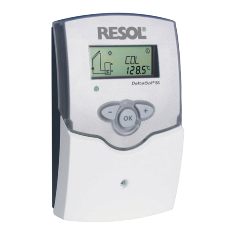
Electronic temperature controller (thermostat)with combi-
ned LCD display for indicating the current temperature and
the setting parameters (menue guided)
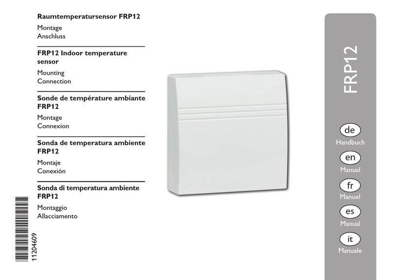
A temperature sensor (PT1000 for example FKP6) from
our catlalogue is needed.
Tecnical data
Housing: plastic, PC-ABS and PMMA
Protection type: IP 20 / DIN 40050
Size: 172 x 110 x 46 mm
Power supply:
220...240V,50 - 60 Hz
Output
1 relais output, breaking capaticity 4(1)A
Ambient temperature:
-20 °C ... +40 °C
Display: LCD, multi-functional combined display
with pictograms two 2-digit text fields and two 4-
digit 7-segment displays as well as one 2-coloured
LED
Mounting: Wall mounting, panel-mounting pos-
sible
Operation: by three pushbuttons
Input: 1 temperature sensor Pt 1000
Output: 1 standard relais (changeover)
Degree of polution: 2
Rating surge voltage: 2,5 kV
Temp. for ball pressure check: 75 °C

TT1 Thermostat
© RESOL 06277 TT1.mon.en.indd
|4
1. Sensor types
Precision-platin sensors type PT1000 (FKP and FRP) are
used for TT1
The arrangement of the sensors is of great importance to
the total efficiency of the regulator.The collector tempera-
ture should be measured in the upper part of the collector.
In stores with integral heat exchanger, the sensor must be
directly mounted in the upper part of the heat exchanger.
When using external heat exchangers, the sensor must be
fixed at the bottom of the store. For individual operation
systems, our product range contains 3 different types of
sensors (sensors for installation in existing immersion slee-
ves, flatscrew sensors or cylindrical clip-on sensors).The
sensor types FK and FR have the same electrical features
and are available in the same models,They only differ in the
connecting cable:
Immersion sensors: in different lengths (immersion
depth) available
FK...60: 60 mm immersion depth, immersion sleeves of
chromium-plated brass
FK...150: 150 mm immersion depth, immersion sleeve of
chromium-plated copper
Important: The sensors must be completely pushed into
the sleeve and the nut must be slightly tightenend.
Cylindrical clip-on sensors: for any pipe diameter; cpl.
with fastening collar; FK...21 or FR...21
Ensure good thermal contact of the sensor with the pipe
work by cleaning the contact area and by applying heat con-
duction paste between sensor and pipe. In order to protect
the sensor cable against outside temperature influences, it
is recommended to insulate the pipe..
Flatscrew sensors: for installation on flat surfaces
FK...9 or FR...9
Ensure good thermal contact. Use conduction paste and in-
sulate the sensors against outside temperature influences.
Indication:
In order to avoid overvoltage damage at the collector (e.g.
by lightening), it is highly recommendend to use the over-
voltage protection RESOL SP1.
FK... : collector sensor
FR... : reference sensor (store sensor)
FK: 1,5 m weather- and temperature resistant silicone cable
for temperatures between -50 °C ...+180 °C, mostly used
for collectors.
FR: 2,5 m PVC cable for tempertures between
-5 °C ...+80 °C, mostly used for stores.
Make sure that all electrical works are carried out according
to the relevant local and IEE-regulations.The sensor cables
carry low voltages and they must not run together in a
cable conduit with cables carrying higher voltages than 50
Volts.When using longer cables or cable conduits,please use
screened cables.The sensor cables can be lengthened up to
100 m, but the cross section must be 1,5 mm² (or 0,75 mm²
up to a cable length of 50m);screened cables should be used
preferably.The sensors must not be in direct contact with
water, please always use immersion sleeves.

TT1 Thermostat
© RESOL 06277 TT1.mon.en.indd
5 |
The unit must only be located internally. It is not suitable
for installation in hazardous locations and should not be
sited near to any electromagnetic field.The controller must
additionally be equipped with an all-polar gap of at least 3 mm
or with a gap according to the valid installaton regulations,
e.g. LS-switches or fuses. Please pay attention to a separate
laying of the cable lines and installation of ac power supply.
1. Unscrew the cross-recessed screw of the cover and
remove it from the housing.
2. Mark the upper fastening point on the underground and
premount the enclosed dowel and screw.
3. Hang up the housing at the upper fastening point and mark
the lower fastening point on the underground (hole pitch
130 mm), afterwards put the lower dowel.
4. Fasten the housing at the underground.
Warning!
Switch-off power supply before
opening the housing.
housing
key field
base
clamps
cover
cable conduits with strain relief
operation control lamp
combined LCD
2.1 Mounting
2. Installation
2.2 Electrical connection The power supply to the controller must only be made by
an external power supply switch (last step of installation!)
and the line voltage must be 220 ... 240 Volt (50...60 Hz).
Flexible lines are to be fixed at the housing by enclosed
strain relief supports and screws.
The controller is equipped with 1 standard relays, to
which the consumers can be connected:
14 = normally closed contact R
15 = middle contact M
16 = normally open contact A
13 = ground clamp
The temperature sensors (S1) will be connected to the
following terminals independently of the polarity:
1 /2 = sensor for heat source / heat sink
The power supply is effected to the clamps::
19 = neutral conductor N
20 = conductor L
12 = ground clamp
net clamps
sensor clamps consumer clamps
Notice:
The middle contact M (15) and the conductor L (18) are
bridged from factory.
After removal of the bridge the changeover contact (RMA)
becomes a potential-free relais.
bond bridge
T4A
PRG
12
S1
Temp. Sensor
Pt1000
LNL’N
201918171312 15 16
MRA
14
TT1
2 (1) A 220...240 V~
fuse

TT1 Thermostat
© RESOL 06277 TT1.mon.en.indd
|6
1
2
3
3 Operation and function
3.1 Pushbuttons for adjustment
The controller is operated by 3 pushbuttons below the
display. The forward-key (1) is used for scrolling forward
through the indication menu or to increase the adjustment
values. The backwards-key (2) is accordingly used for the
reverse function.
The adjustment channels follow the pure indication channels
in the display. In order to come to these channels, press the
forward key to channel HO for 2 sec. If an adjustment
value is shown on the display, SEt is indicated. In this case
you can press the key „Set“ (3) in order to change into
input mode.
Select a channel by keys 1 and 2
Shortly press key 3, so that „SEt“ flashes
Adjust the value by keys 1 and 2
Shortly press key 3, so that „SEt“ permanently appears,
the adjusted value is now saved
backwards forward
set
(selection / adjustment mode)
3.2 Controller parameter / indication channnels
• TT
Thermostat Temperature
• HO
Hours of Operation
• TD
Time Delay
• TO
Temperature On
• TF
Temperature ofF
• DO
Delay On
• DF
Delay ofF
• MM
Manual Mode
• PG
ProGramm
• VN
Version Number
3.3 Adjustment channel TO
If the sensor temperature TT declines the adjusted switch-
on temperature TO the controller switches the relais on.
The symbol appears in the display and the status-LED
is iluminated green.
The relais stays turned off during the adjusted switch on de-
lay (DO)to avoid ineffective switching on/off of the relais.
TO: Switch-on temperature
Adjustment range -20 ... 150 °C
Factory setting 40,0 °C
TT1.mon05229en.pdf

TT1 Thermostat
© RESOL 06277 TT1.mon.en.indd
7 |
3.6 Adjustment channel DF
The relay is not switched off until the switch-off delay (DF)
is expired to avoid ineffective switching off of the realy.
DF: Switch-off delay
Adjustment range
00:00 ...05:00 min
Factory setting 00:00 min
3.5 Adjustment channel DO The relay is not switched on until the switch-on delay (DO)
is expired to avoid ineffective switching on of the realy.
DO: Switch-on delay
Adjustment range
00:00 ...05:00 min
Factory setting 00:00 min
3.4 Adjustment channel TF If the sensor temperature TT exceeds the in TF adjusted
switch-off temperature the controller switches the relais off.
The symbol disappears in the display and the status-LED
is iluminated red.
The relais stays turned off during the adjusted switch off de-
lay (DF)to avoid ineffective switching on/off of the relais.
TF: Switch-off temperature
Adjustment range -20 ... 150 °C
Factory setting 45,0 °C
3.7 Adjustment channel MM
In this channel the automatic or manual mode can be choo-
sen. In the manual mode the relais can be switched on or
off manualy.
0the relais is switched off permanently
1the relais is switched on permanently
2 automatic mode
Manual mode
0 = Off
1 = On
2= Auto
MM: Manual mode
Adjustment range 0, 1, 2
Factory setting 2 (Auto)
green: Relais/pump switched on
red: Relais/pumpe switched off
green/red blinking: Initialisation
Sensor failure
Manual mode
3.8 Status-LED Blinkcodes
TT1.mon05229en.pdf

TT1 Thermostat
© RESOL 06277 TT1.mon.en.indd
|8
T4A
PRG
12
S1
Temp. Sensor
Pt1000
LNL’N
201918171312 15 16
MRA
14
TT1
2 (1) A 220...240 V~
Sicherung
Attention!
Before opening the housing
please make sure that all poles
are separated from the line
voltage.
5. Tips for fault location
Please check the following points if the controller
does not work faultlessly:
1. Power supply
If the operating control lamp is off, please check the power
supply of the controller.
The controller is protected by one can fuse T4 A, which is
situated at the base/isolation plate and can be replaced by
opening the cover of the housing (spare fuse is enclosed in
one of the accessory bags).
2. Sensor failure
If there is a malfunction due to a sensor defect, the opera-
ting control lamp flashes red and the symbol is shown
on the display. An error code for the concerned sensor is
shown on the display.
Short-circuit: Short-circuit in the sensor wire with
indication of the concerned temperature
sensor(TT). The error code -888.8 is
shown on the display.
Line-break: Interruption of the sensor wire with
indication of the concerned temperatu-
re sensor (TT).The error code 888.8 is
shown on the display.
Clamped Pt1000-temperature sensors can be checked by
a resistance-measuring device.The measured temperatures
can be compared with the resistance values of the table
opposite.
resistance values of
PT1000 sensors
can fuse T4A
4. Commisioning
Ac power supply must be activated.The controller passes
an initialisation phase in which the operating control lamp
flashes red and green.
If individual conditions require an adaptation of the parame-
ter, please adjust the values accordingly (vgl. 3.3).
Your wholesaler:
Notes
Design and specifications are subject to change without notice.
Illustrations may differ slightly from production models.
Table of contents
Other Resol Temperature Controllers manuals