RESQ RPX200 User manual

EN
SV
NO
DA
FI
DE
IT
FR
ET
简体中文
PL
ES
TR
PT
CS
NL
INSTRUCTIONS FOR USE &
INSPECTION CARD FOR
RPX200 & EPX200

FOR YOUR OWN SAFETY, IT IS
IMPORTANT THAT YOU READ
AND FULLY UNDERSTAND
THIS MANUAL!
EN
INSTRUCTIONS FOR
USE & INSPECTION CARD
FOR
1 INTRODUCTION 2
2 MARKING & ILLUSTRATIONS 3
3 USING RPX200 & EPX200 4
4 TECHNICAL DATA 5
5 EQUIPMENT 5
6 OPERATION 6
7 MAINTENANCE AND INSPECTION 9
8 INSPECTION CRITERIA 10
9 SUSTAINABILITY & RECYCLING 10
10 COMPLIANCE 10
11 LOG 11
12 EXPERT USE 12
RPX200 & EPX200 | Master EN | v.1 | 1
RESQ
RPX200 & EPX200

This document gives information about the correct use of the RESQ RPX200 & EPX200 in different situations. These instructions
must be read and fully understood by all persons who are going to use the RESQ RPX200 & EPX200. We also recommend that
all employers must read these instructions carefully, to ensure a good safety level together with a full understanding of the product
and its use. Users shall be trained in the use of the equipment.
1 INTRODUCTION
This emergency equipment is designed for evacuation from height, and operates automatically, descending in a bi-directional
format. It can be used for one or two persons descending at the same time with a controlled descent speed of 0,5-2m/s. It is tted
with an integrated rescue lifting function that can be used to lift one to two persons, in accordance with the limitations for load and
distances set out under “Technical data” in this user instruction.
This equipment is made in accordance with the European PPE Regulation 2016/425 and complies with EN341:2011 Descender
device class C; EN1496:2017
Applicable as evacuation equipment from Wind turbines, tower cranes, sky lifts, buildings, towers etc
Warning! The equipment shall only be used by a person trained and competent in a safe use.
Warning! The user-/s must be in good physical and mental condition. In case of known disorder, the user must be aware of pos-
sible consequences, as conditions such as cardiovascular conditions, diabetes, blood pressure deviations, epilepsy and balance
problems or any other medical condition that can be hazardous to the safety using the equipment.
Warning! Equipment use must be supported by the company’s own accident emergency procedures related to daily work.
Warning! Do not make any alternations or additions to the equipment without the manufacturer´s prior written consent, and any
repair shall only be carried out in accordance with the manufacturer´s procedures and guidelines.
Warning! Do not use the equipment outside its limitations or for no purpose other than that which it is intended.
Warning! The equipment must only be used for rescue and evacuation and not intended as fall arrest equipment or as a utility
crane.
EPX200RPX200
| v.1 | Master EN | RPX200 & EPX200 |2

2 MARKING & ILLUSTRATIONS
1. Read the user instructions before use.
2. Brake house - Warning! Very hot
3. Rope markings (at both rope ends)
If possible, mark the device with the date of inspection or date for next inspection.
Note! Make sure that the product markings are legible or that the RFID is readable.
12
3
RPX200 & EPX200 | Master EN | v.1 | 3

3 USING RPX200 & EPX200
3.1 USE/PRE-CHECK
1. Note! Before use of the equipment always check the function and condition to ensure safe usage. If stored in the Cresto
vacuum solution, only check that the vacuum is still intact. If punctured, you must inspect the function and condition of the
equipment before use.
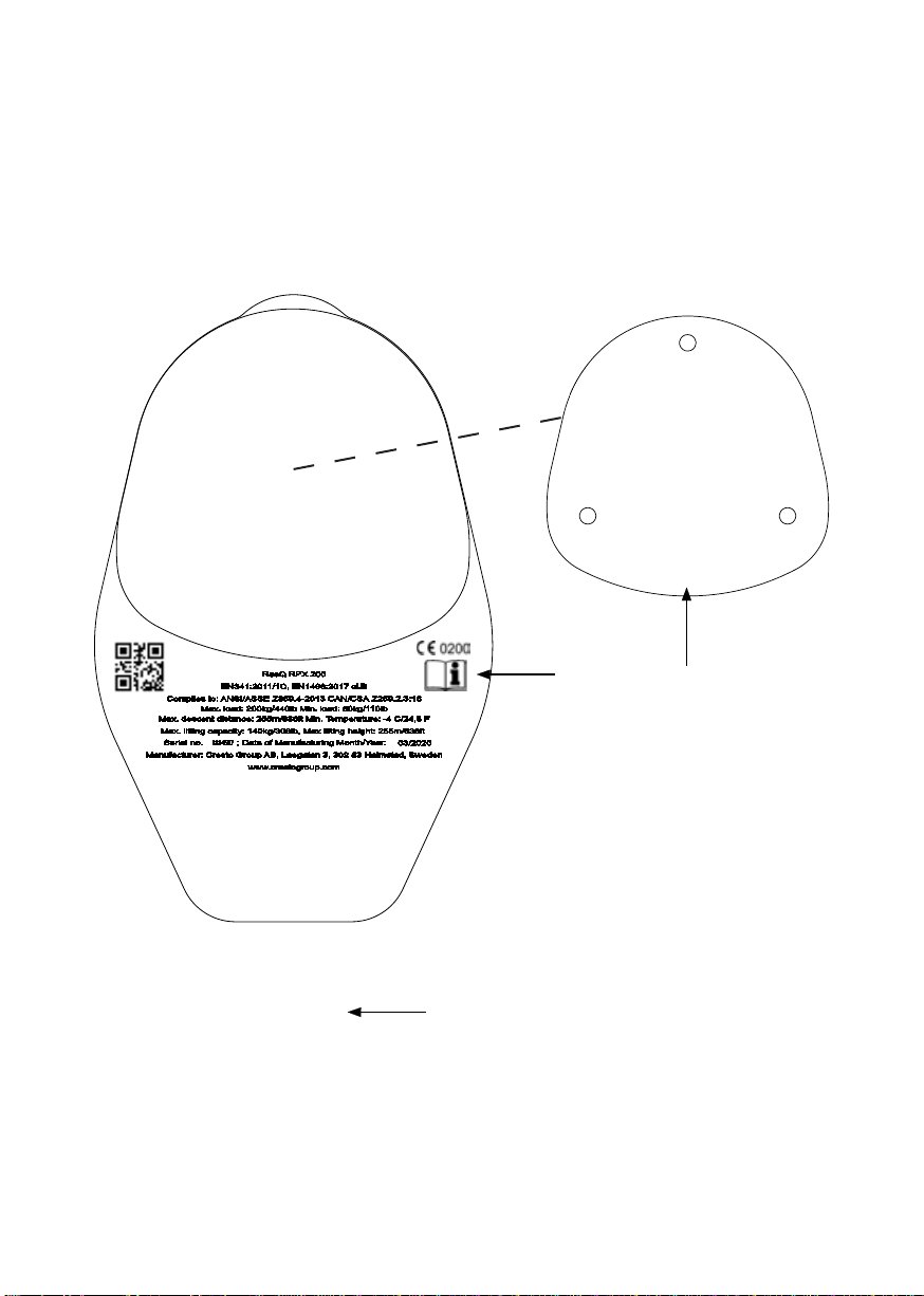
2. Check the legibility of the markings of the device and rope end.
3. Check the rope along its entire length for any signs of chang, varying thickness, cuts, chemical especially acids contact,
change of shape, UV-deterioration, stiffness or other deformation with permanent kinks. Check the stitches in the end
terminations for any loose threads or damage. Check the carabiners in the rope and equipment for any signs of signicant
corrosion, wear, deformation, cracks and limited gate function. Check the descender device for any cracks, deformation or
missing parts. While pulling the rope thru the device, check for any “wobble” in the handwheel. Test the brake function of the
device by pulling the rope through the device hard for at least 3m in each direction (Note: that the brake force must increase
with increased pulling power). Check the friction loops for any deformation. Check the function and spring action of the rope
locking mechanism.
Warning! Withdraw the device immediately until conrmed in writing by a competent person if any doubts arise about its condition
for safe use or if it has arrested a fall.
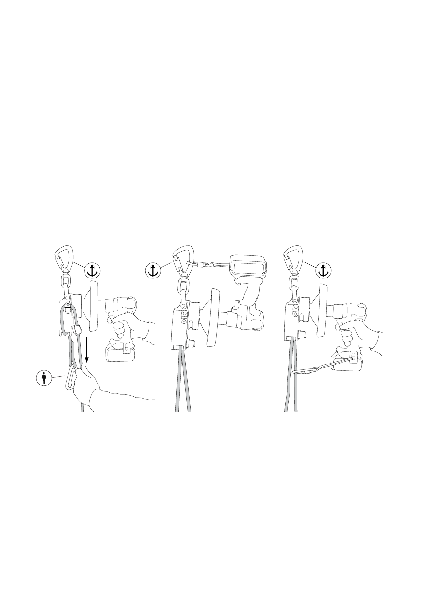
Warning! Always use a fall arrest system if there is a risk for fall when rigging the equipment.
Warning! Always ensure that in a fall-arrest system, it is essential to check for clearance below the user before each use, to avoid
any impact with the ground or an obstacle in case of a fall. Make sure that the anchor point is correctly positioned, to limit the risk
and the height of fall. When using multiple pieces of equipment together, a dangerous situation can arise if the safety function of
one piece of equipment is affected by the safety function of another piece of equipment.
Warning! Extreme temperatures may affect the capacity of the device.
Warning! Protect the rope for any edges that may compromise its integrity.
Warning! Long descent distance with minimum load in high wind and trailing rope may affect the descent speed as the trailing
rope will create a counter force.
Warning! Always have an operator operating the device when top mounted if entanglement of the rope will occur and block the
descent. Last person-/s evacuating will have to body mount the equipment to remain in control.
Warning! During descent the handwheel will spin fast and may cause burn injuries.
Warning! Be careful not to get your hand or ngers inside the handwheel while running. This can cause severe injuries.
Note! Always position the device so that the handwheel doesn’t come in contact with any structure as this can slow down the
descent or result in a complete stop.
Compatible with PPE components within EN, ANSI or CSA designed for the purpose
Note! This must always be in conjunction with the national and local requirements
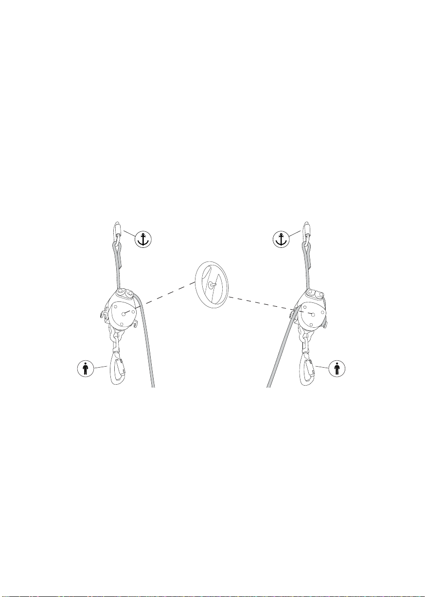
Only connect to a structure with a minimum strength of 12kN or designed for the purpose. Strive to position as high above as
possible and protect from edges that could damage the rope.
To be used with fall arrest harness EN361, Rescue harness EN1497 or rescue slings EN1498.
See user instruction of the body holding device for correct attachment of the equipment.
| v.1 | Master EN | RPX200 & EPX200 |4

4 TECHNICAL DATA
Type RESQ RPX200 & EPX200
Rope Kernmantle rope 9,6 mm EN 1891:1998 A
Material/Construction Rope Polyamide/Polyamide; Elongation: 3,8%; Mass: Cover 40%; Core 60% Weight: 62g/m,
Sheet slippage <1,5%, Shrinkage
Certication EN341:2011 cl.C 200 kg (RPX200 & EPX200)
EN1496:2017 cl.B (RPX200)
Compliance ANSI/ASSE Z359.4-2013
CAN/CSA Z259.2.3:16
Max descent height 255 m
Max descent load 200 kg - for 280kg see chapter 12. Expert use
Min. descent load 40 kg
Max. ambient temperature +60°C
Min. ambient temperature -30°C (-40°C in RESQ vacuum solution packaging)
Max. lifting capacity 140 kg (RPX200) for 280kg see chapter 12. Expert use
Max. lifting height 255 m (RPX200)
Max. height/load descending 1 x 255 m with max. load 200 kg
Descent velocity 1,3m/s loads from 40 kg. Increasing speed when load is increased, max. speed of 1,7m/s
Calculation of descend energy W= m * g * h * n
m= descent load (kg), g= 9,81 m/s2, h= descent distance (m), n= number of descents
Class A: W=0,5 x 10 6J
5 EQUIPMENT
1. Device carabiner
2. Swivel
3. Handwheel
4. Rope clamp
5. Rope carabiner
6. Friction loop
7. Trailing rope
8. House (position of marking)
9. Rope groove
10. Brake house
9
EPX200RPX200
1
2
3
4
5
7
8
6
10
RPX200 & EPX200 | Master EN | v.1 | 5

6 OPERATION
6.1 LOCKED OFF POSITION
6.1.1 TOP MOUNTED
Pull the trailing rope thru the friction loop and into the rope clamp to lock the device.
6.1.2 BODY MOUNTED
Pull the rope thru the rst friction loop into the rope groove and over the second friction loop. Insert the rope into the rope clamp.
6.2 BASIC EVACUATION - GENERAL INFORMATION
Secure the equipment to the anchor point at least one meter above the platform. Check that the intended descent path is free of
any obstacle that may obstruct the descent. Throw the rope bag to the ground if this is appropriate and done responsibly.
Alternatively, the bag can travel with the rst evacuee or be left at the exit
level.
Note! The last evacuee MUST descend with the device (body mounted)
and carry the rope bag, if the bag hasn´t already been dropped to the
ground.
Note! If not necessary, do not stop the descent until you have reached the
ground to minimize the risk of having the rope meet any hot surfaces of
the device.
6.3 BASIC EVACUATION - TOP MOUNTED
1. Attach the rescue rope carabiner to the harness attachment point
(marked with A) or approved body holding device in accordance with
its user instruction. Remove any slack between the you and the device
by pulling the trailing rope downwards. Hold on to the trailing rope
while transferring the load into the device. Carefully swing free of the
platform and ease the grip around the trailing rope to begin the
descent.
Note: Always keep control/grip around the trailing rope as it might be
impossible to regain control if lost. RPX200 EPX200
RPX/EPX locked/hands off position top mounted RPX/EPX locked/hands off position body mounted
(RPX200)
| v.1 | Master EN | RPX200 & EPX200 |6

Warning! The body of the device will accumulate heat from the brake and may be HOT enough to damage the rope if not adminis-
trated correctly. Always use protective gloves when operating the device and rope.
2. Once the rst person-/s have reached the ground and disconnected from the equipment, the next person may hook onto the
trailing rope (which subsequently becomes the rescue rope) using the carabiner at the end (or making a gure of 8 knot if the
equipment length is not site specic depending on rope length and descent height).
Warning! If a gure of 8 knot is used instead of the end carabiner always ensure that it is place on the correct end, if wrongfully
placed the descent may be blocked by the knot. Always pull through an extra meter or two on the former rescue rope to ensure
room for the knot to ensure that next evacuee reaches the ground. The lowering process described with continuous lowering of
several evacuees one after the other is called “shuttling”. When evacuating several persons ensure that this complies with the
maximum descent and load according to the specication under technical data.
6.4 BASIC EVACUATION - BODY MOUNTED
1. Attach the rescue rope carabiner to the anchor point. Attach the device carabiner to the harness attachment point (marked
with A) or approved body holding device in accordance with its user instruction. Remove any slack between you and the
device by pulling the trailing rope upwards. Hold on to the trailing rope while transferring the load into the device. Carefully
swing free of the platform and ease the grip around the trailing rope to begin the descent.
Note! If possible, try to position the device so the handwheel faces away from the user-/s to minimize risk of injuries.
2. To decrease or manually control the descent speed e.g. in narrow spaces, add friction by passing the rope thru the friction loop
and rope groove of the device.
6.5 BASIC LIFTING - TOP MOUNTED
1. Attach the equipment to an anchor point directly via the device carabiner or with a anchor sling at least 1 meter above the
casualty.
2. Pull out the rescue rope so you can attach it to the casualty’s harness (upper attachment point).
3. Remove any slack between you and the device by pulling the trailing rope downwards.
4. Pull the trailing rope through the friction loop and insert the rope into the rope clamp and tighten.
5. Start to lift by turning the handwheel in clockwise direction with two hands. Frequently tighten the slack between the friction
loop and rope clamp. Approx. after every 10 turns on the handwheel.
Note! Secure if necessary the trailing rope around the device to eliminate the risk of unintentional descent.
6. Free the casualty from its fall arrest
7. Start the control descent by releasing the trailing rope from the rope clamp by pulling it outwards.
Warning! Never let go of the trailing rope as it could be difcult to regain control if lost.
6.4.26.4.1
(RPX200)
RPX200 & EPX200 | Master EN | v.1 | 7

Note! Always verify lifting progress by looking at the rope colour threads movement in and out of the device.
6.6 BASIC LIFTING - BODY MOUNTED
1. Attach the rescue rope to an anchor point directly via the rope carabiner or with a anchor sling at least 1 meter above the
casualty.
2. Pull the device towards the casualty so you can attach it to the casualty’s harness (upper attachment point)
3. Remove any slack between you and the device by pulling the trailing rope upwards.
4. Pull the trailing rope through the rst friction loop into the rope groove of the brake housing, around the second friction loop,
insert the rope into the rope clamp and tighten.
5. Start to lift by turning the handwheel in clockwise direction with two hands. Frequently tighten the slack between the friction
loop and rope clamp. Approx. after every 10 turns on the handwheel.
Note! Secure if necessary the trailing rope around the device to eliminate the risk of unintentional descent.
6. Free the casualty from its fall arrest
7. Start the control descent by releasing the trailing rope from the rope clamp by pulling it downwards.
6.5.76.5.4
6.6.4
| v.1 | Master EN | RPX200 & EPX200 |8

Warning! Never let go of the trailing rope as it could be difcult to regain control if lost.
Note! Always verify lifting progress by looking at the rope colour threads movement in and out of the device.
6.7 BASIC LIFTING - WITH POWER SOURCE
Note! Always secure any tools to prevent falling objects.
1. Attach the power source to the extended pinion in the centre of the handwheel.
2. Secure the machine to eliminate risk of dropping it to the device carabiner or operator with a tool lanyard.
3. Pull the trailing rope through the rst friction loop into the rope groove of the brake housing, around the second friction loop,
insert the rope into the rope clamp and tighten.
4. Start lifting with the machine and continuously tighten the slack between the locking clam and device.
Note! Depending on machine, if equipped with an anti-torsion function the steps 3, 4 & 5 is mandatory to carry out a safe lifting
procedure. When using a recommended machine by Cresto Group, without anti torsion function, you may lift without following
steps 3, 4 & 5 when utilizing the optional connection sling connected to the rescue rope or device carabiner.
5. If transition from lifting to descending is required, lock of the device, reverse with the machine until the rope is full loaded
before removing the machine from the pinion.
Warning! When using a power source, be very cautious when lifting a casualty if you are not able to visually see or communicate
with him/her, if he/she would be caught in something during the lift it might lead to person injury or overload of the device. entang-
lement, due to the enhanced risk of further injury.
7 MAINTENANCE AND INSPECTION
The rescue and evacuation equipment is an emergency equipment and must be inspected after it has been used. The equipment
must be service and repacked by a Cresto authorized competent person.
Note! During transport and storage, keep the equipment dark and dry.
Inspection and service of the equipment must be carried out by the manufacturer or a partner whom is authorized by the manufac-
turer and in accordance with the manufacturers guidelines.
If stored, maintained as described and used in normal condition, the expected lifespan of this device is 10 Years. Note: For RESQ
RPX/EPX vacuum sealed, see “Vacuum solution manual” for extended lifetime, inspection intervals and service guidelines.
Note! If the equipment is installed at a workstation and left in place between inspections it must be protected by the RESQ vacuum
solution to ensure protection from environmental conditions.
Note! The device shall be stored in a dry, dark and well-ventilated location, protected against steam, sharp edges, vibration and
6.7.4 6.7 Optional 6.7 Optional
RPX200 & EPX200 | Master EN | v.1 | 9

UV-light. The device shall be kept clean for best functionality and durability. Metal parts can be blown clean with compressed air.
Avoid lubricating oil! Lightly soiled devices can be washed with a brush in lukewarm water. A mild soap solution can be used. Wet
devices is hung up to dry. The device shall be allowed to air-dry without being subjected to open re or any other heat source.
The device log on the last page must be updated with all periodic inspections, service and repairs and other matters concerning
the safe use of the device, if the Cresto database Inspector is not utilized.
Warning! For the user’s safety the device shall be inspected at least every twelfth month in order to ensure its functionality and
durability (refer to EN 365). The inspection can be registered in Inspector online at www.crestogroup.com
Note! In cases of frequent usage of the device or in aggressive environments, inspections shall be carried out at shorter intervals
(as decided by a trained competent person).
Warning! The inspection shall be carried out by a competent person (a person who has been trained and is competent in fall
protection equipment inspection) who holds a certicate for inspection and in accordance with the manufacturer’s inspection
procedure as well as EN 365.
Warning! The device must not be modied or supplemented using accessories other than those supplied by the manufacturer.
Repairs or replacement of parts may only be carried out by the manufacturer.
Warning! Do not make any alterations or additions to the equipment without the manufacturer’s prior written consent, and any
repair shall only be carried out in accordance with manufacturer’s procedures.
8 INSPECTION CRITERIA
Rope: Check the entire length of the rope for damage including cuts, nicks, abrasion, fraying, discolorations, heat or chemical
damage, UV degradations and moisture. Check the terminations and stitching for damage.
Connectors: Check gate function, abrasion, deformation, corrosion, cracks and nicks
Device: Check for any signs of corrosion, cracks nicks, deformation, abrasions. The device must opened for inspections to verify
that the rope housing and gears are without damage and or corrosion.
Markings: Legibility of marking, serial no. date of manufacturing
9 SUSTAINABILITY & RECYCLING
We design and manufacture premium products, with premium materials, to be used actively and to last long. When the product is
decided to be taken out of use, or its maximum lifetime has expired, it should be recycled according to your local legislations. Our
products are made of polyester, polyamide or PVC and metal components. If necessary, dismantle the metal components before
recycling. You can also send the complete product to Cresto Group and we will take care of the recycling to reduce our impact on
the environment.
10 COMPLIANCE
Manufacturer:
Cresto Group AB
Lägatan 3
SE-302 60, Halmstad, Sweden
+46 (0) 35 710 75 00
crestogroup.com
EU Type Examination by:
Notied Body: 0200
FORCE Certication A/S
Park Allé 345
DK-2605 Bröndby, Denmark
Phone: +45 43250177
Fax: +45 43250010
info@forcecertication.com
Production control by:
Notied Body: 0200
FORCE Certication A/S
Park Allé 345
DK-2605 Bröndby, Denmark
Phone: +45 43250177
Fax: +45 43250010
info@forcecertication.com
| v.1 | Master EN | RPX200 & EPX200 |10

Warning! It is essential for the safety of the user that if the product is re-sold outside the original country of destination the reseller
shall provide instructions for use, for maintenance, for periodic examination and for repair in the language of the country in which
the product is to be used.
Download your user instruction and Declaration of Conformity at http://www.crestogroup.com/documentation or scan the
QR-code.
11 LOG
Date Log item
Name and signature
of the competent person
Next due date for
periodic examination
Company: Product: Descender device, class C
User: Reference:
Marking: CE 0200 Length:
Date of Purchase: Serial number:
Date of
manufacturing:
Date rst put into
use:
RPX200 & EPX200 | Master EN | v.1 | 11

12 EXPERT USE
12.1 280 KG DESCENT WITH RESQ RPX200 & EPX200
Note! Descending with exceeded load over 200 kg requires additional friction and is limited to one descent of total 255 m.
Warning! The brake house will accumulate heat during long descents which may cause melt damage to the rope sheat.
12.2 280 KG DESCENT WITH TOP MOUNTED RESQ RPX200 & EPX200
1. Attach the device to the anchor point directly or with the anchor sling EN795 cl B around a sufcient structure.
2. Pull the trailing rope through the rst friction loop into the rope groove of the brake housing, around the second friction loop
3. Connect the rescue rope to the harness attachment point of person 1 and use an additional carabiner between the rescue
rope carabiner to the harness attachment point of person 2.
4. Remove any slack between the persons and the device.
5. Hold rmly the trailing rope until the persons load is transferred to the device.
Note! This conguration requires that you have an operator operating the descent next to the equipment. See following chapter for
body mounted conguration.
6. Start the descent by easing the grip around the trailing rope.
12.3 280 KG DESCENT WITH BODY MOUNTED RESQ RPX200 & EPX200
1. Attach the rescue rope to the anchor point directly or with the anchor sling EN795 cl B around a sufcient structure.
2. Pull the trailing rope through the rst friction loop into the rope groove of the brake housing, Manage the rope so it remains into
the rope groove.
3. Connect the device to the harness attachment point of person 1 and use an additional carabiner between the device carabiner
to the harness attachment point of person 2.
4. Remove any slack between the persons and the device.
5. Hold rmly the trailing rope until the load is transferred to the device.
Warning! Make sure that any fall arrest systems are disconnected prior to the start!
12.2.2 12.3.2
(RPX200)
| v.1 | Master EN | RPX200 & EPX200 |12

12.4 280 KG LIFTING WITH RPX200
Note! If needed, the RPX200 will handle shorter lifting operations with up to 280 kg. This excess of load will increase the force onto
the handwheel. And should only be used for short lifting operation e.g. ”pick off” rescue.
Note! Be aware of slippage when lifting loads over 210 kg. If slippage occurs, put a slight counterpull onto the trailing rope.
Warning! Always use both friction loops when handling loads over 140 kg of lifting. It might be impossible in the transition from
lifting to descending to stop the descent if not congurated for loads over 200 kg.
12.4
RPX200 & EPX200 | Master EN | v.1 | 13


FÖR DIN EGEN SÄKERHET ÄR DET
VIKTIGT ATT DU LÄSER IGENOM
OCH FÖRSTÅR INNEHÅLLET
I DENNA BRUKSANVISNING!
SV
INSTRUKTIONER FÖR ANVÄNDNING
OCH BESIKTNINGSKORT
FÖR
1 INLEDNING 2
2 MÄRKNING OCH ILLUSTRATIONER 3
3 ANVÄNDA RPX200 OCH EPX200 4
4 TEKNISKA DATA 5
5 UTRUSTNING 5
6 ANVÄNDNING 6
7 UNDERHÅLL OCH INSPEKTION 9
8 KONTROLLPUNKTER 10
9 HÅLLBARHET OCH ÅTERVINNING 10
10 ÖVERENSSTÄMMELSE 10
11 LOGGBOK 11
12 EXPERTANVÄNDNING 12
RPX200 & EPX200 | Master EN | v.1 | 1
RESQ
RPX200 & EPX200

Det här dokumentet innehåller information om hur RESQ RPX200 och EPX200 används i olika situationer. Alla som kommer att
använda RESQ RPX200 & EPX200 måste läsa igenom och förstå dessa anvisningar i sin helhet. Vi rekommenderar också att alla
medarbetare läser igenom anvisningarna noggrant så att en bra säkerhetsnivå kan garanteras tillsammans med en full förståelse
för produkten och dess användning. Alla användare ska utbildas i hur utrustningen används.
1 INLEDNING
Denna nödutrustning är konstruerad för evakuering från höjd och fungerar automatiskt för nedstigning i ett dubbelriktat format.
Den kan användas för nedrning av en eller två personer samtidigt med en kontrollerad nedstigningshastighet på 0,5–2 m/s.
Den är utrustad med en integrerad räddningslyftfunktion som kan användas för att lyfta en eller två personer, i enlighet med de
begränsningar för belastning och avstånd som anges under ”Tekniska data” i denna bruksanvisning.
Denna utrustning är tillverkad i enlighet med den europeiska PPE-förordningen 2016/425 och uppfyller kraven enligt
SS-EN341:2011 Nedrningsdon klass C; SS-EN1496:2017
Gäller som evakueringsutrustning från vindkraftverk, tornkranar, lyftkranar, torn osv.
Varning! Utrustningen får endast användas av en person som är utbildad och behörig för säker användning.
Varning! Användaren måste vara i god fysisk och mental form. Om användaren har ett bekräftat sjukdomstillstånd måste
denne vara medveten om möjliga konsekvenser, eftersom till exempel hjärtproblem, diabetes, högt eller lågt blodtryck, epilepsi,
balansproblem eller något annat medicinskt tillstånd som kan äventyra säkerheten när utrustningen används.
Varning! Användningen av utrustningen måste stödjas av företagets egna rutiner vid arbetsplatsolyckor.
Varning! Gör inga ändringar av eller tillägg till utrustningen utan föregående skriftligt medgivande från tillverkaren, och eventuella
reparationer får endast utföras i enlighet med tillverkarens förfaranden och riktlinjer.
Varning! Använd inte utrustningen utanför dess begränsningar eller för något annat ändamål än det som den är avsedd för.
Varning! Utrustningen får endast användas för räddning och evakuering och är inte avsedd att användas som fallskyddsutrustning
eller som en verktygskran.
EPX200RPX200
| v.1 | Master EN | RPX200 & EPX200 |2

2 MÄRKNING OCH ILLUSTRATIONER
1. Läs igenom bruksanvisningen före användning.
2. Bromshus – Varning! Mycket varmt
3. Repmarkeringar (i båda repändarna)
Om möjligt, märk enheten med datum för inspektion eller datumet för nästa inspektion.
Obs! Kontrollera att produktmärkningarna är läsbara eller att RFID-tekniken är läsbar.
12
3
RPX200 & EPX200 | Master EN | v.1 | 3

3 ANVÄNDA RPX200 OCH EPX200
3.1 ANVÄND/FÖRKONTROLL
1. OBS! Före användning av utrustningen ska dess funktion och skick alltid kontrolleras för att säkerställa säker användning. Om
utrustningen lagras i Crestos vakuumlösning räcker det att kontrollera att vakuumet fortfarande är intakt. Om vakuumlösningen
skulle ha punkterats, ska utrustningens funktion och skick kontrolleras före användning.
2. Kontrollera att alla markeringar på enheten och repänden är läsbara.
3. Kontrollera repet i hela dess längd för eventuella tecken på nötning, varierande tjocklek, snitt, kontakt med kemikalier –
i synnerhet syror, ändrad form, försämring till föjd av exponering för UV-strålning, stelhet eller andra deformeringar med
permanenta halvknutar. Kontrollera stygnen i repändarna med avseende på lösa trådar eller skador. Kontrollera karbinhakarna
i repet och utrustningen för tecken på betydande korrosion, slitage, deformering, sprickor och begränsad spärrfunktion.
Kontrollera nedrningsbromsen med avseende på sprickor, deformering eller saknade delar. Var observant på eventuella
”wobblande rörelser” hos handratten när du drar repet genom enheten. Testa enhetens bromsfunktion genom att dra
repet genom enheten hårt minst 3 m i vardera riktningen (OBS: bromskraften måste öka med ökad dragkraft). Kontrollera
friktionsslingorna med avseende på deformering. Kontrollera funktionen och fjäderfunktionen hos replåsmekanismen.
Varning! Sluta omedelbart att använda enheten tills en behörig person skriftligen på om det är säkert att använda enheten eller om
den har dämpat ett fall.
Varning! Använd alltid ett fallskyddssystem om det nns en risk för fall vid riggning av utrustningen.
Varning! I ett fallskyddssystem är det viktigt att alltid säkerställa ett fritt fallutrymme under användaren före och efter användning
för att undvika att användaren slår i marken eller ett hinder i händelse av ett fall. Kontrollera att förankringspunkten är korrekt
placerad för att begränsa risken och fallhöjden. Vid användning av era utrustningsdelar tillsammans kan det uppstå en farlig
situation om säkerhetsfunktionen på en del av utrustningen påverkas av säkerhetsfunktionen hos en annan utrustningsdel.
Varning! Extrema temperaturer kan påverkan enhetens kapacitet.
Varning! Skydda repet mot eventuella kanter som kan äventyra dess integritet.
Varning! Lång nedstigningssträcka med minimal belastning vid stark vind och nedrningsrep påverkar nedstigningshastigheten
eftersom nedrningsrepet kommer att skapa en motkraft.
Varning! Se till att alltid ha en operatör som hanterar enheten när denna är toppmonterad om repet skulle sno sig och blockera
nedstigningen. Den person/de personer som evakueras sist måste montera utrustningen på kroppen för att behålla kontrollen.
Varning! Vid nedstigning kommer handratten att snurra snabbt och kan orsaka brännskador.
Varning! Se upp så att din hand eller ngrarna inte hamnar innanför ratten när denna snurrar. Detta kan orsaka allvarliga skador.
Obs! Placera alltid enheten så att handratten inte kommer i kontakt med någon struktur eftersom detta kan bromsa upp
nedstigningen eller göra att det helt tar stopp.
Kompatibel med PPE-komponenter i EN, ANSI eller CSA avsedda för ändamålet
Obs! Detta måste alltid ske i samband med de nationella och lokala kraven
Anslut endast till en struktur med en minsta hållfasthet på 12 kN eller som är avsedd för ändamålet. Sträva efter att placera
enheten så högt ovanför som möjligt och skydda mot kanter som kan skada repet.
För användning tillsammans med fallskyddssele EN361, räddningssele EN1497 eller räddningsslingor EN1498.
Se bruksanvisningen för selen för korrekt fastsättning av utrustningen.
| v.1 | Master EN | RPX200 & EPX200 |4

4 TEKNISKA DATA
Typ RESQ RPX200 och EPX200
Lina Kernmantel-rep 9,6 mm EN 1891:1998 A
Material/konstruktion rep Polyamid/Polyamid; Förlängning: 3,8 %; Massa: Mantel 40 %, Kärna 60 % Vikt: 62 g/m,
Sheet slippage <1,5 %, Krympning
Certiering SS-EN 341:2011 cl.C 200 kg (RPX200 och EPX200)
SS-EN 1496:2017 cl.B (RPX200)
Överensstämmelse ANSI/ASSE Z359.4-2013
CAN/CSA Z259.2.3:16
Max. nedstigningshöjd 255 m
Max. nedstigningsbelastning 200 kg - för 280 kg se kapitel 12. Expertanvändning
Min. nedstigningsbelastning 40 kg
Max. omgivningstemperatur +60 °C
Min. omgivningstemperatur -30 °C (-40 °C i RESQ vakuumlösningförpackning)
Max. lyftkapacitet 140 kg (RPX200) för 280 kg se kapitel 12. Expertanvändning
Max. lyfthöjd 255 m (RPX200)
Max. höjd/belastning
nedstigning
1 x 255 m med max. last 200 kg
Nedstigningshastighet 1,3 m/s laster från 40 kg. Hastigheten ökar när belastningen ökar, maxhastighet på 1,7 m/s
Beräkning av nedstigningsenergi V= m * g * h * n
m= belastning vid nedstigning (kg), g= 9,81 m/s2, h= nedstigningssträcka (m),
n= antal nedstigningar
Klass A: W=0,5 x 10 6J
5 UTRUSTNING
1. Karbinhake
2. Svivel
3. Handratt
4. Repklämma
5. Karbinhake rep
6. Friktionsslinga
7. Nedrningsrep
8. Hus (position för markering)
9. Repspår
10. Bromshus
9
EPX200RPX200
1
2
3
4
5
7
8
6
10
RPX200 & EPX200 | Master EN | v.1 | 5
This manual suits for next models
1
Table of contents
Languages:
Other RESQ Safety Equipment manuals