Resvent iBreeze Series User manual

IBREEZE SERIERS PRODUCTS
BPAP/CPAP/AUTO CPAP
Positive Pressure Therapy Device Service Manual
iBreeze Series
Published: October 31, 2017
Copyright © Resvent Medical Technology Co., Ltd

iBreeze Service Manual RX/HR01-3-04(1.1)
1 / 49
Copyright
Resvent Medical Technology Co., Ltd (referred as Resvent )has the copyright of this
non-public publication and has the right to treat it as a confidential information. This manual
is only used as reference material for the maintenance of medical products, and other persons
are not entitled to disclose the contents of this manual to others.
This manual contains proprietary information protected by copyright law. No person or
organization may reproduce, modify or translate any part of this manual without the
authorization from Resvent.
Note
This maintenance manual is based on the most complete configuration of this product, so
some of the content may not apply to the products you repair. If you have any questions,
please contact the company's after-sales service department.
Version
The version number of this maintenance manual may be upgraded at any time due to changes
in the software or technical specifications without prior notice. The version information of
this maintenance manual is as follows
█ Version:1.1
█ Published:October 31, 2017
Announcement
Resvent have the right to the final interpretation of this manual
Resvent reserved the right of updated the service manual without prior notice.
Resvent reserved the right of modifying product specifications without prior notice.
Resvent does not assure include (not limited to) the implied warranties of
merchantability and fitness for a particular purpose.

iBreeze Service Manual RX/HR01-3-04(1.1)
2 / 49
Resvent consider its responsibilities under below circumstances:
Assembly operation, expansion, re-adjustment, improvement and repair done by
Resvent employee;
All maintenance related to replacement parts and ancillary use of accessories
consumables are supplied by Resvent or Resvent authorized parties.
The Devices are operated by Resvent User manuals
Resvent are not responsible for below circumstances:
Components are disassembled, stretched, debugged
None Authorized person personnel maintenance or alteration of equipment
Products are not used correctly in accordance with the user manuals
Guarantee
Manufacturing process and raw materials:
Under regular use and maintenance, Resvent guarantees its products and material will not
malfunction during the warrantee time.
Service:
Free of Charging:
Free maintenance services are available for products that comply with Scope of

iBreeze Service Manual RX/HR01-3-04(1.1)
3 / 49
Warranty Services Ordinance;
Charging Service:
Any product exceeding the scope of the Warranty Service Ordinance;
Even in the warrantee period, the cause of service under below circumstances: man
made damage, misuse, Environment, irresistible natural disasters, unauthorized parts
and consumable replacement and unauthorized service personnel
Contact Information
Address:
A602 Building 1, Phase II Gaoxinqi Industrial Park, 1st Liuxian Road,
Baoan district, Shenzhen P.R. China
Tel:
+86-755-23027370
Fax:
+86-755-23027370
Post Code:
518100
Web:
Http://www.resvent.com
Safety
Cautionary Language
In this service manual,
Cautionary words include danger, warning, caution and note for safety
and other important instructions。The definition of cautionary language:(notice:before
reading this manual,please clearly understand what they mean)
<Danger>:The indication of an urgent risk condition, if not avoided, will
lead to death or serious injury.
<Warning>:Indicates a potential risk condition that, if not avoided, can lead
to death or serious injury.
<Caution> :Indicates a potential risk condition that, if not avoided, can
cause minor or moderate damage.
<Note>:Indicates a potential risk condition that, if not avoided, can cause
minor or moderate damage.

iBreeze Service Manual RX/HR01-3-04(1.1)
4 / 49
Safety Symbols
During the usage,Please notice the following symbol for safety purposes.
Safety Symbol
Meaning
Humidifier is been heated, please do not touch the heating parts
Does not suitable working in the NMR enviornment
Please follow the instruction manual

iBreeze Service Manual RX/HR01-3-04(1.1)
5 / 49
Content
1 Device Overview................................................................................................................ 6
1.1 Device Information...............................................................................................................6
1.2 Device Composition............................................................................................................. 6
1.3 Device outer structural components..................................................................................... 7
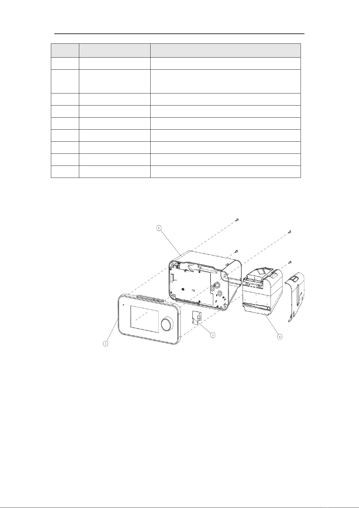
1.4 Device Disassemble Diagram...............................................................................................8
2 Hardware Schematic Description.....................................................................................10
2.1 Power Adaptor.................................................................................................................... 10
2.2 Main Control PCBA........................................................................................................... 11
2.3 Key Button Set....................................................................................................................11
2.4 Encoder PCBA....................................................................................................................11
2.5 SD PCBA............................................................................................................................11
2.6 Flow PCBA.........................................................................................................................11
2.7 Wireless PCBA................................................................................................................... 12
2.8 Screen..................................................................................................................................12
2.9 Touch Screen and Front Panel............................................................................................ 12
2.10 Turbine..............................................................................................................................12
3 Gas Flow Diagram............................................................................................................12
Chapter 2 Device and Software Operation Instruction.................................................................... 13
1. Starting the device............................................................................................................ 13
2. Software Structure and Operation Theory........................................................................13
3. Software Interface.............................................................................................................14
4. Software Update............................................................................................................... 17
5. Alert.................................................................................................................................. 17
Chapter 3 Common Troubleshooting Guidelines.............................................................................18
1. Device Failure...................................................................................................................19
2. Function Failure................................................................................................................20
3. Vent/Device Alert..............................................................................................................21
4. Other Failure.....................................................................................................................25
Chapter 4 Positive Pressure Therapy Device Service...................................................................... 25
1. Front housing service........................................................................................................26
2. Rear Housing Service....................................................................................................... 29
3. Calibration........................................................................................................................ 33
Chapter 5 System Check after Service............................................................................................. 38
Chapter 6 Other.................................................................................................................................38
1. Clean the Device...............................................................................................................38
2. Water Tank Cleaning.........................................................................................................38
3. Tube Cleaning...................................................................................................................39
4. Storage and Discard..........................................................................................................39
Chapter 7 Service Part List……………………………………………………………………………………………………….39
Appendix I Wiring Diagram of the Device...................................................................................... 41
Appendix 2 Product Technical Specifications..................................................................................42
Appendix 3 Sleep Quality Report Terminology interpretation........................................................ 45

iBreeze Service Manual RX/HR01-3-04(1.1)
6 / 49
Chapter 1 Overview
1 Device Overview
The device provides positive airway pressure support to patients with sleep apnea syndrome
(OSA) by establishing pressure differential by turbine mechanism in order to produce the
kinetic principle of alveolar ventilation. This can also be used to replace, control or change a
person’s spontaneous breathing to achieve treatment goals.
1.1 Device Information
*This manual will use CPAP 20A Pro and BPAP Tech as models。
1.2 Device Composition
The device consists of tube, mask, power, housing and other major parts. The main
machine includes:
-Front housing set
BPAP front housing (touch screen) / CPAP front housing (none touch screen)
3.5 inches screen set /5 inches screen set
Key Board Assembly
Rotary Encoder(including knob)
iBreeze Series includes:4 models of 3.5 inches screen CPAP and 10models of
5inches screen BPAP.
CPAP:iBreeze 20C、iBreeze 20C Pro、iBreeze 20A、iBreeze 20A Pro
BPAP:iBreeze 25S、iBreeze 25A、iBreeze 25A Pro、iBreeze 25ST、iBreeze 25STA、
iBreeze 25STA Pro、iBreeze 30ST、iBreeze 30STA、iBreeze 30STA Pro、iBreeze Tech
Chart 1-1 iBreeze Tech
Chart 1-2 iBreeze 20A Pro

iBreeze Service Manual RX/HR01-3-04(1.1)
7 / 49
Environmental Light Plate Assembly
Other:Waterproof strip
- Rear housing set
Rear housing
Inlet lid and filter
SD PCBA /SD connection wire /SD Lid/SD Card
DC Power Cord
Turbine set
Water tank set
Heating plate set
Main PCBA board
Wireless PCBA:2G module or wifi/blue tech module
Gas link parts(flow sampling tube, water tank intake tube, water tank outtake tube,
external outtake tube)
Water level sensor/water level stopper
other:rear housing lid、water tank lid and heating plate lid
1.3 Device outer structural components
Item
Function
Description
1
Start/Stop Button
Start/Stop the gas flow
2
Ramp
Start ramp function
Chart 1-3 iBreeze Tech front view
Chart 1-4 iBreeze Tech back view

iBreeze Service Manual RX/HR01-3-04(1.1)
8 / 49
Item
Function
Description
3
LCD Screen
Displaying the content on the screen
4
Knob
Turning the knob to change parameters and push in
for confirming the change
5
Water tank side plate
Holding and protecting water tank
6
Water tank
Contain the humidifying water
7
Gas outlet
Connecting to a breathing tube
8
Power inlet
Connecting a power cord
9
SD lid
Opening lid to insert a SD card
10
Gas inlet
Inhale gas inlet
11
Filter lid
To open the filter lid to change the filter
1.4 Device Disassemble Diagram
①Rear housing set
②Front housing set
③wireless PCBA
④water tank
1.5 Front/Rear housing set wiring diagram
Here displays only the diagram, the detailed wiring map is in Appendix I
Chart 1-5 iBreeze Tech Disassembling Chart

iBreeze Service Manual RX/HR01-3-04(1.1)
9 / 49
1.5.1 Front housing wiring diagram
Attention:iBreeze 20C does not include ambient light set.
Attention:Above chart is an example diagram,Actual shape is subject to object
1.5.2 Rear Side wiring Diagram
Key button PCBA
Front Shell
Encoder PCBA
Screen Set
Chart 1-6 iBreeze CPAP(3.5 inches)Front Shell backside view
Chart 1-7 iBreeze BPAP(5 inches)front shell backside view
Key plate and
encoder
connector
Ambient light
PCBA wiring
Ambient Light
PCBA
Encoder and main PCBA
connector
Key button PCBA
Front Shell
Encoder PCBA
Screen Set
Key plate and
encoder
connector
Ambient light
PCBA wiring
Ambient Light
PCBA
Encoder and
main PCBA
connector

iBreeze Service Manual RX/HR01-3-04(1.1)
10 / 49
2 Hardware Schematic Description
The hardware is showing as below diagram and includes power adopter、main control
board、key button set、encoder PCBA、SD PCBA、flow PCBA、wireless PCBA、screen、
touch screen(BPAP)and turbine.
2.1 Power Adaptor
Chart 1-8 iBreeze rear shell view
Chart 1-9 Hardware Structural Diagram
SD PCBA and
Main PCBA
connector
Inside DC
Transmission
Turbine Hall
Line
Turbine wire
Heating plate
connector
2G/wifi
antenna
Wireless PCBA and
main PCBA connector

iBreeze Service Manual RX/HR01-3-04(1.1)
11 / 49
Power adapter for the overall supply of power, contains of over voltage, over-current,
and over-temperature protection function. Its input/output parameters are showing below
Table1 Power adapter input and output parameters
Parameter
Value
Input
100VAC-240VAC 50/60Hz
Output
24VDC-28VDC 2.5A Max
2.2 Main Control PCBA
Main control board in charge of computer interaction, turbine control and parameter
monitoring. The parameters include the power supply voltage, atmospheric pressure, ambient
light intensity, tube pressure, tube flow, ambient temperature and humidity.
The main control board and other boards or components connected by wire connection,
including DC input wire, SD card board connection wire, encoder board connection wire, key
button Board connector, wireless Board connector.
2.3 Key Button Set
The key button PCBA is provided with a vent start/stop button, a ramp button, and a
ventilation status indicator. Stop ventilation shows blue and in ventilation shows in green. The
key button PCBA is connected with the main control board through the encoder PCBA.
2.4 Encoder PCBA
The encoder PCBA is connected with the main control board through the wire, with
rotating and switching functions, the user can adjust the display cursor position through the
encoder and press the knob for confirmation selection.
2.5 SD PCBA
The SD card PCBA is connected directly with the main control board through the wire,
and the SD card is used to store the treatment data, upgrade the software, and machine state.
In addition, the SD card PCBA is provided with a micro USB interface for machine
calibration.
2.6 Flow PCBA
The flow PCBA is assembled on the top of a turbine box for real-time monitoring of tube
gas flow. The flow PCBA is also connected with the main control PCBA through the wire.

iBreeze Service Manual RX/HR01-3-04(1.1)
12 / 49
2.7 Wireless PCBA
The wireless PCBA is divided into two optional configurations, wifi board and 2G board,
and one machine is configured with only one wireless board, which is used to connect a
network platform or an external wireless module (such as a SPO2 module).
2.8 Screen
The screen is an important part of human-computer interaction to display the ventilation
parameters and configuration options. The display size is divided into two kinds, 3.5 inch and
5 inches, which the size of display is related to the model.
2.9 Touch Screen and Front Panel
Touch screen using capacitive screen, is also an important interface for human-computer
interaction, and used to match the BPAP model;
The front Panel is primarily cosmetic and decorative, and provides a transparent square
area in the display area for a CPAP and APAP models.
2.10 Turbine
The turbine is assembled in the turbine box, which is the core part of the machine, with
the built-in rotational speed and temperature sensor, corresponding to the gas pressure and
flow according to the different output of the ventilation mode.
3 Gas Flow Diagram
With the turbine fan as the power source, the ambient atmosphere is boosted, and the
pressure or flow pattern is output to the patient through the feedback control algorithm.
The process requires the pressure and flow sensor as feedback input.
By means of heating the water, the humidification of the gas is provided. And the
complex ventilation mode, the wetting adjustment, has the algorithm realization.
• F:Flow Sensor
Chart 1-10 Gas Flow Diagram

iBreeze Service Manual RX/HR01-3-04(1.1)
13 / 49
• T:Turbine Temperature Sensor
• P:Pressure Sensor
• Muffler:Noise Reduction
• Resistance:Gas Stopper
• BLOWER:Turbine Housing
• HUMIDIFLER: Humidifier(Consists of Water tank and heating plate)
Chapter 2 Device and Software Operation Instruction
1. Starting the device
Confirm the connection of power supply, boot logo showing in the screen and boot
waiting interface in 5 seconds, then the device enters the patient standby interface;
After the factory reset, the language and time setting interface are automatically showing
on the screen. Need to complete setup these parameters before entering patient standby
interface
Attention:
When in the patient standby interface, press ramp key + control knob 5 seconds to enter
the doctor standby interface.
When in the doctor standby interface, press ramp key + control knob 5 seconds to enter
the patient standby interface.
2. Software Structure and Operation Theory
The System program of Ibreeze series positive pressure ventilation treatment device is
composed of bootloader, application, and buzzer control programs.
iBreeze series BPAP/CPAP application program are system programs used by users;
Buzzer control program is mainly used to detect the accidental power off and alarm
prompts;
Bootloader Program is mainly used for system storage allocation, restore factory
settings, upgrade results feedback, and upgrade process error prompts.
2.1 System Application Software Hierarchy Diagram

iBreeze Service Manual RX/HR01-3-04(1.1)
14 / 49
Core Layer
Domain Layer
UI Layer
3. Software Interface
3.1 Patient Software Interface
The patient menu mainly includes the patient's standby interface shortcut operation, the
ventilation interface shortcut operation, the patient setting interface, the comfort adjustment
interface, and the patient Information interface.
3.1.1 Patient standby interface:
The patient's standby interface shows SD card, pre-heating status, wireless/ Bluetooth
connection status icon, current treatment mode, mask matching degree, humidity adjustment,
sleep treatment report, comfort adjustment, and System Setup function. Click function button
to enter corresponding function setting interface.
Chart 2-1 System Application Software Hierarchy
Diagram

iBreeze Service Manual RX/HR01-3-04(1.1)
15 / 49
#
Feature
Description
1
Mode
Display the current mode.
2
Enabled Features
Depending on setup, certain enabled therapy
features will display here.
3
Time
Display the current time.
4
Patient Sleep
Quality Report
Displays the patient sleep quality report and the
options for period of the report are: daily
(recent 6 days) / 7 days / 14 days / 1 month / 3
months / 6 months / 1 year.
5
Humidity
Set humidifier level to enhance patient comfort
of respiration.
Option: Auto / 0-8 Default: 3
Note: The humidity level only can be set when
the water in humidifier exceeds the minimum
water level for safe operation.
6
Mask Fit
Mask fit feature allows you to check the fit of
your mask prior to starting therapy. This is done
by measuring the amount of leak.
7
Comfort
Press to enter Comfort setting interface.
8
Setting
Press to enter Patient System Setting interface.
9
Alarm Message
Display the alarm messages.
3.2 Doctor Standby Interface
The Doctor interface mainly includes the patient standby interface shortcut operation, the
ventilation interface shortcut operation, the patient setting interface, the comfort adjustment
Chart 2-2 Patient Standby Interface

iBreeze Service Manual RX/HR01-3-04(1.1)
16 / 49
interface, the patient report interface and the alarm setting.
3.2.1 Doctor Standby Interface:
The doctor standby interface has more features and parameter settings than the patient
standby interface.
#
Feature
Description
1
Therapy Mode
Displays the current mode and you can click here to set the Therapy
Mode
2
Patient Sleep
Quality Report
Displays the patient sleep quality report and the options for period
of the report are: daily (recent 6 days) / 7 days / 14 days / 1 month /
3 months / 6 months / 1 year.
3
Humidity
Humidity level setting, Enhance patient comfort of respiration.
Option: Auto / OFF / 1 to 8
Default: 3
When auto humidity is enabled, the control algorithm adjusts the
humidifier output to maintain a constant humidity level of 85%
relative humidity while protecting against rainout.
Note: The humidity only can be set when the water is higher than
the limit level in the humidifier.
Chart 2-3 Clinical standby interface

iBreeze Service Manual RX/HR01-3-04(1.1)
17 / 49
#
Feature
Description
4
Mask fit
Mask fit test:
In the selection of a new mask, need to test the face mask to wear
whether the occurrence of leakage
In standby or therapy mode, click on the mask fit test icon, display
mask fit test in process with the animation interface
5
Comfort
Press Comfort key, enter Clinical comfort setting interface
6
Setting
Press Setting key, enter Clinical System Setting interface
7
Parameters
Settings
Sets the parameters of the current therapy mode. Press the More
button to view more parameters.
8
Alarm
Message
Display the alarm messages.
3.3 Service
In the doctor standby interface sequentially click Setting → Service →input password
into the service interface
Attention: All operations performed at the service interface must be authorized and
trained by the manufacture. Unauthorized performance should be held accountable.
4. Software Update
In the doctor interface sequentially click Setting →Service →Upgrade
4.1 Software Update Methods
4.1.1 SD Card Update:Use the SD card which is load with update software;
5. Alert
5.1 Alert Type
Chart 2-4 Software Update Interface

iBreeze Service Manual RX/HR01-3-04(1.1)
18 / 49
Alert 0:The status bar displays a gray-white tip, which will always be displayed
until the alarm condition is no longer satisfied;
Alert 1:The status bar displays yellow and white tips, the start/Stop button has a
Blu-ray flashing, and there is an alarm sound, the alarm will always be displayed
until the alarm condition is no longer satisfied
Alert 2 :Status bar display red background white tip, the Start/Stop button has a
Blu-ray flashing, and there is an alarm sound, the alarm for the exclusive alarm, will
be displayed until the user open the reminder point to confirm or click on the
Start/stop button;
Notice :The status bar displays white and white prompts, and the notification
message disappears automatically when the corresponding process is finished
5.2 Alert Setup
In the setting interface → Click Alert into alert setting
Chapter 3 Common Troubleshooting Guidelines
Due to various factors (such as voltage instability, environmental temperature changes,
fall and impact, components aging, etc.), iBreeze series positive pressure therapy device may
malefaction and affect normal use in the state of transportation, storage, and usage. At this
point, there should be an experience professional engineer of medical equipment to carry out
the maintains task under the instruction following breakdown classification. The so-called
part-level overhaul refers to the component analysis, substitution, trail run, and locate the
failure to the components of the instrument such as main PCBA, turbine, display module and
other parts. Parts maintenance of the component-level must be carry out by the manufacturer.
Chart 2-5 Alert List Interface

iBreeze Service Manual RX/HR01-3-04(1.1)
19 / 49
This chapter provides a description of the replacement subassembly for a common failure.
The calibration and component-level maintenance is usually returned to the Resvent factory
for execution.
We divided failure into 4 groups
1. Device Failure
No.
Description
Possible Reason
Resolving
1
After the power on,
no display in the
screen, no light in
the power indicator
and no sound from
buzzer
1) Loose connect with
power adaptor or
power adapter failure.
2) Internal DC
connection failure
3) Main PCBA failure
1st. Check and replace power
adaptor
2nd. Replace DC connection
wire
3rd. Replace main PCBA
2
No display in the
screen but the power
indicator shines
light
1) Screen wire loose
2) Screen malfunction
3) Main PCBA failure
1st. Reconnect Screen wire
2nd. Replace Screen
3rd. Replace main PCBA
3
Device Crash
Software BUG or main
PCBA malfunction
1st. Restart the mahcine
2nd. Update software
3rd. Replace main PCBA
4
Repeatedly appears
power off/
self-restart
Power connection
malfunction
1st. Check the power adapter
and the main PCBA
connection
2nd. Check and repair the
inside DC connection
Device Failure
Other Failure
Function Failure
Vent/Device Alert
Chart 3-1 Failure Category
Other manuals for iBreeze Series
2
Table of contents
Other Resvent Medical Equipment manuals