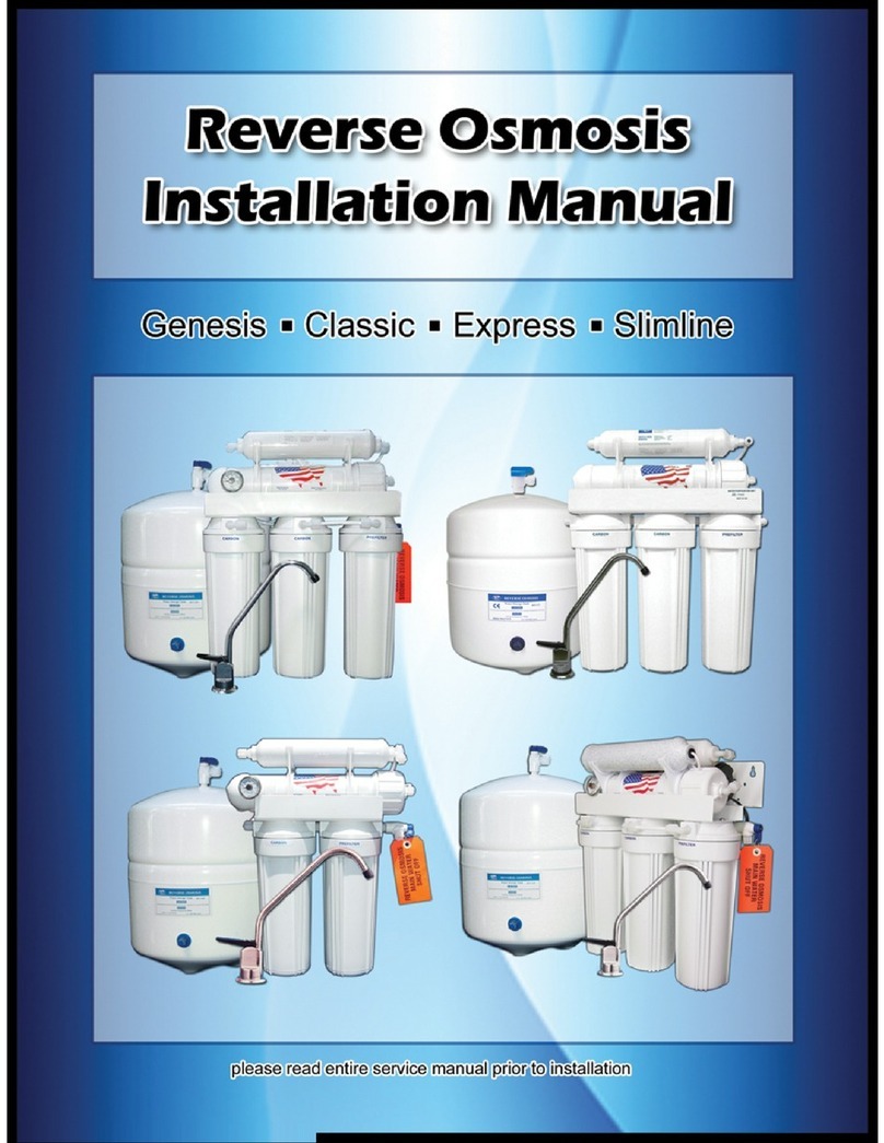
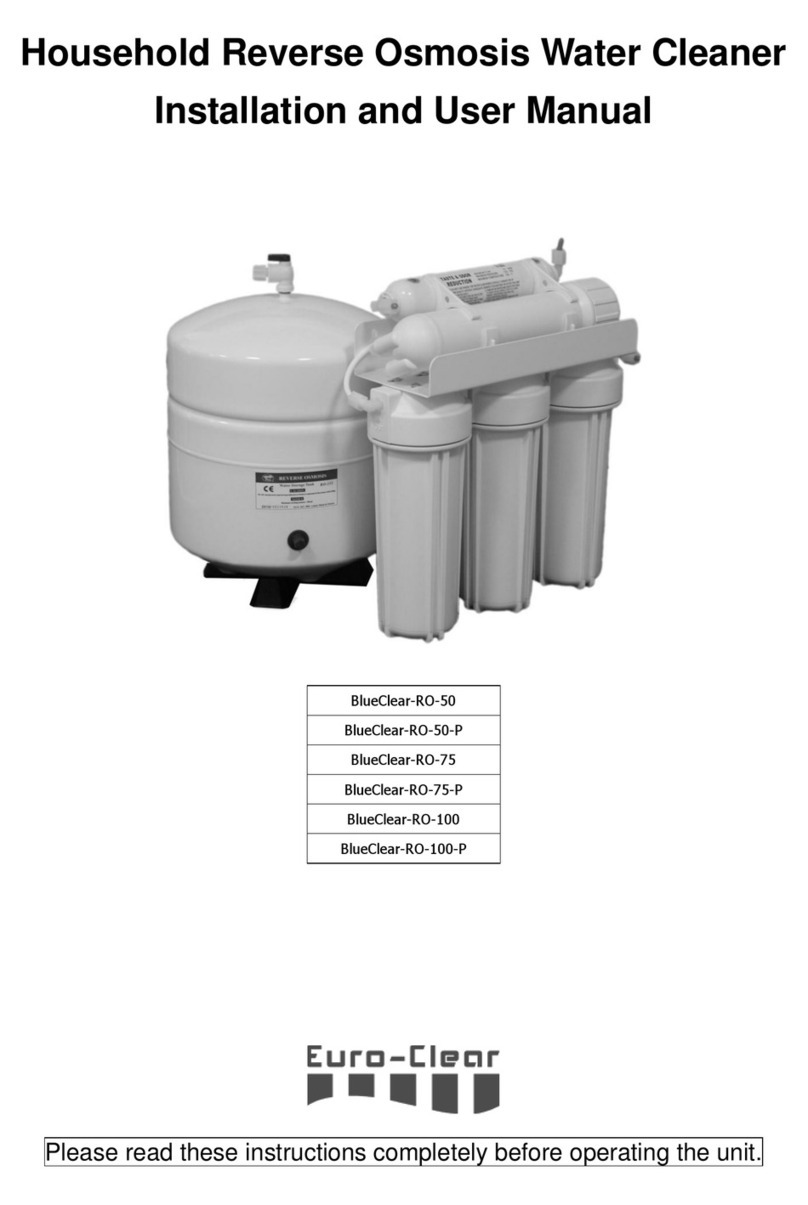
Reverse Osmosis RO-300G User manual

Installation Manual
RO-300G & RO-600G
WATER PURIFICATION SYSTEM
RO-300G-600G_manual.indd 1 6/28/16 3:57 PM

Page 2 of 12
RO-300G & RO-600G
WATER PURIFICATION SYSTEM
I. Introduction .......................................................................................................................................3
II. Identication of Components and Parts ............................................................................... 3
III. System Specications ....................................................................................................................4
IV Reverse Osmosis Process Terminology ...................................................................................5
a. Water Quality .................................................................................................................................5
b. Rejection Ratio..............................................................................................................................5
c. Water Production Available .....................................................................................................5
d. Percent Recovery .......................................................................................................................5
e. Water Pressure and Temperature ..........................................................................................5
f. Permeate Flow ..............................................................................................................................5
g. Request for Technical Assistance ..........................................................................................5
V. Installation Instructions and Startup....................................................................................... 6
VI. Operation and Maintenance ...................................................................................................... 7
VII. Diagrams and Tank Conguration Options ..........................................................................8
a. Flowcharts ......................................................................................................................................8
b. Pressure Tank Conguration ..................................................................................................8
c. Atmospheric Tank Conguration ..........................................................................................8
VIII. Quick Connectors ............................................................................................................................9
IX. Precautions and Tips ......................................................................................................................9
X. Operating Parameters ................................................................................................................ 10
XI. Troubleshooting and Solutions Guide ................................................................................. 10
XII. Liability and Warranty ................................................................................................................. 12
WARNING: READ ENTIRE MANUAL. FAILURE TO FOLLOW ALL GUIDES AND RULES COULD CAUSE
PERSONAL INJURY OR PROPERTY DAMAGE.
CHECK WITH YOUR STATE AND/OR LOCAL PUBLIC WORKS DEPARTMENT FOR PLUMBING CODES.
WARNING: DO NOT USE WITH WATER THAT IS MICROBIOLOGICALLY UNSAFE OR OF UNKNOWN
QUALITY WITHOUT ADEQUATE DISINFECTION BEFORE OR AFTER THE SYSTEM.
NOTE: Failure to comply with these installation instructions will void the product Warranty, and the installer will be
responsible for any service, repair or damages caused thereby.
Table of Contents
RO-300G-600G_manual.indd 2 6/28/16 3:57 PM

Page 3 of 12
RO-300G & RO-600G
WATER PURIFICATION SYSTEM
I. INTRODUCTION
Your new water purier works through a process called reverse
osmosis in which water of a concentrated solution is applied
pressure and forced through a semipermeable membrane for
achieving a diluted pass across the membrane or low-salt solution.
When water passes through the membrane, dissolved
minerals contained in the feed water as concentrated
solution are rejected and sent to the drain.
The system is designed for low-salt puried water through 4
stages and we recommend it for domestic use and commercial
to have water for drinking, cooking, preparing drinks, ice and
food processing in general.
1. Pre-ltration up to 5 micron sediment particles
removed by suspending
2. Pre-ltration cartridge coal block to remove
chemical contaminants
3. Reverse osmosis membrane, which reduces total
dissolved solids levels (TDS)
4. Post-ltration on activated carbon block to rene
water taste .
This system automatically operates through several components:
low pressure switch, solenoid valve, pump booster and switch
high pressure, same as they are installed properly so that when a
full tank of storage you have, the system shuts down and when
no feed water pump switch has no team.
The RO-300G & RO-600G models are a basic version of a business
osmosis model with attractive price and guarantees a salt
retention of up to 97%.
Please be sure to read this manual before proceeding with the
installation to become familiar with the terms and parties.
II. COMPONENTS IDENTIFICATION AND SPARE PARTS
FOR MAINTENANCE
Model
# Description Part Number 300 600
1 Filter Housings HF4-20WHWH38 3 3
2 Sediment Cartridge (5M) SDC-25-2005 1 1
3 Carbon Block Cartridge CB-25-2010 2 2
4 RO Membrane Housing MH03-3012 1 2
5 RO Membrane TW-3012 1 2
6 Booster Pump - Aquatrol PMP-300GPD 1 2
7 Plastic Mounting Clip CLP-30W 2 4
8 Low Pressure Switch PMP-LPS14 1 1
9Solenoid Valve (3/8”) BSV-38110V 1 1
10 High Pressure Switch PMP-TSO14 1 1
11 Pressure Gauge 0-150 PSI PG15150B 1 1
12 Quick connect Fittings Several 1 kit 1 kit
13 Polyethylene tubing ( 3/8") PT-6-WH-0500 1 kit 1 kit
14 Polyethylene tubing (1/4") PT04-BL-0500 1 kit 1 kit
15 Feed Valve ( 3/8") WNV-2 1 1
16 Filter Wrench FW-1 1 1
17 RO housing wrench FW-5 1 1
18 Pressure Regulator - Shok Blok SB-FPV-60 1 1
19 Flow Restrictor IFR-3000A 1 1
20 Check Valve - Hydrot HDF-ICV04 1 2
21 Inline Valve - Hydrot HDF-BVI04 1 1
22 Metal Bracket Double level 1 1
Introduction / Identication
2 16 17 183 51 4 6 14 158 137 12 19 209 10 11 21
RO-300G-600G_manual.indd 3 6/28/16 3:57 PM

Page 4 of 12
RO-300G & RO-600G
WATER PURIFICATION SYSTEM
System Specications
RO-300G RO-600G
III. RO300G & RO600G SYSTEM SPECIFICATIONS:
WARNING! DO NOT USE WHERE THE WATER IS MICROBIOLOGICALLY UNSAFE OR OF UNKNOWN QUALITY WITHOUT
ADEQUATE DISINFECTION BEFORE OR AFTER THE SYSTEM.
PRETREATMENT MUST BE SUFFICIENT TO ELIMINATE CHEMICALS, ORGANICS OR INOR-GANICS THAT COULD ATTACK THE
MEMBRANE MATERIAL ALWAYS TURN OFF THE UNIT, SHUT OFF THE FEED WATER, AND DISCONNECT THE ELECTRICAL
POWER BEFORE WORKING ON THE UNIT.
NEVER ALLOW THE PUMP TO RUN DRY.
NEVER ALLOW THE UNIT TO FREEZE OR OPERATE WITH A FEED WATER TEMPERATURE ABOVE 100°F.
WARNING! WARRANTY IS VOID AND COMPANY ASSUMES NO RESPONSIBILITY FOR SYSTEM OR PROPERTY DAMAGE IF
THE SUPPLY PRESSURE IS OVER 80 PSI.
17.5 in (444.5 mm)
10.5 in
(266.7 mm)
32 in
(812.8 mm)
17.5 in (444.5 mm)
10.5 in
(266.7 mm)
32 in
(812.8 mm)
RO-300G-600G_manual.indd 4 6/28/16 3:57 PM

Page 5 of 12
RO-300G & RO-600G
WATER PURIFICATION SYSTEM
Reverse Osmosis Process Terminology
IV. REVERSE OSMOSIS PROCESS TERMINOLOGY
a. Water Quality:
Water quality from an RO system is normally determined with
a TDS Meter, which measures total dissolved solids in water,
measuring conductivity. The results are normally measured in
parts per million or milligrams per liter. (ppm o mg/lt) Fewer
dissolved solids results in higher quality water.
b. Rejection Ratio:
The least amount of TDS means a higher water quality.
Osmosis membranes are classified by the amount of total
dissolved solids (minerals) refuse and are expressed as a
percentage of rejection.
For example:
If feed water contains 100 ppm of dissolved solids and the
product water after the membrane has 10 ppm of dissolved
solids the rejection rate is 90%.
Formula:
Percent
Rejection =(Feed H2O TDS - Product H2O TDS) x 100
Feed H2O TDS
NOTE : All TDS data must be expressed in the same units, typically parts per
million (PPM) or milligrams per liter (mg / L).
c. Water Production Available:
Each system is designed with an especic ow rate acording to
the size of the membrane(s) and it will be referencing the water
production ow capable to produce.
This capacity is indicated as gallons per day in consideration of
24 hrs of operation.
The ow of water owing into the drain is called wastewater and is
measured in Gal/Day.
The feedwater ow is the sum of currents product water
and waste water.
d. Percent Recovery:
It is another way to measure the amount of water
produced compared to the amount of water used.
Formula:
Percent
Recovery =Product H2O Rate x 100
Feed H2O Rate
e. Water Pressure and Temperature:
Product water quality and production of RO systems is dependent
on pressure and temperature.Typically, RO membranes are treated
at standard conditions of 77 °F (25 °C) y a 100 PSI.
In general, the higher the pressure dierential and temperature,
the greater the quality and quantity of water produced.
These factors should be considered when sizing RO systems
for a particular application.
f. Permeate Flow (variable)
Permeate ow should be within 20% of the rated production,
after correcting the feedwater temperatures above or
below 77 ° F.
For example:
5 gpm @ 59˚ F (5÷1.42=3.52 gpm)
5 gpm @ 77˚ F (5÷1=5 gpm)
5 gpm @ 84˚ F (5÷0.89=5.62 gpm)
g. Request for Technical Assistance
If service assistance is required, please complete
the following process.
Contact your local dealer or distributor. Prior to making the call,
have the following information available:
System installation date, series number, daily log sheets, current
operating parameters (e.g. ow, operating pressures, pH, etc.)
and a detailed description of the problem.
RO-300G-600G_manual.indd 5 6/28/16 3:57 PM

Page 6 of 12
RO-300G & RO-600G
WATER PURIFICATION SYSTEM
V. INSTALLATION AND STARTUP INSTRUCTIONS:
- System Location: Select a place with enough space to install
your system close to an area where you have available potable
water (cold line), drain and electrical power 120 V.
- Take out the box your system and identify all the components.
Start placing RO membrane into the housing membrane. You
can temporarily disconnect the tubing that feeds the input of RO
housing cap threated , using the wrench you can loosen the cap.
Remove membrane from bag and place in the RO housing with
the external oring directed towards the outer side of the cap.
- Tighten the cap with the wrench until get a good seal to prevent
leakage. Return the RO housing to the main original position and
put together tubing and connector removed.
- Install the feed valve’s system, this will be placed in the supply
line of cold water in your sink, place the pressure regulator about
2 ft from the water feed valve and scroll the tubing to where the
purifying equipment is to be installed, place it on the system ‘s
feed that is at the entrance of the sediment lter.
- Make sure the lter holders are tight and also to make the
circulation of its line of drainage where applicable. The drain line
is the nal connection of the membranes and waste water is high
in salts minerals that should be discarded and not recommended
to reuse this water to feed the system again and to cause serious
damage to the membranes.
- Install the valve arrangement of puried water at the point of
choice and also place the storage tank in its nal position, then
the hydraulic preparations corresponding thereto.
- Do not forget to place a key storage tank outlet that
will help in future repairs and maintenance of their post-
treatment to close the line of purified water.
- Before electrically connecting the system to make sure there
are no leaks in the supply line opening the stopcock, if it detects
any leakage repair it before continuing.
- Let the water ow for at least 5 minutes before electrically
connecting the equipment to ensure that the holder lled with
water pre-treatment and also be releasing the air the system.
- We recommend starting at rst produce osmosis water allowing
free passage for the connections to check that there is no leakage
in their connectors which should keep the key nal disposition
open and close the tap of the tank. The water began to come out
of the faucet until it lls before the post-carbon lter and that can
take up to 5 minutes.
- Dispose of the initial product/permeate (clean) water until the
TDS level/conductivity of the product water stabilizes at the
lowest (cleanest) value. Use any TDS or Conductivity meter to
monitor the product water quality. Once the system has been
ushed and the TDS level has stabilized, the permeate/product
line can be attached to the storage tank. Additional ushing of
the storage tank and distribution system may be required to
reach the TDS level that is produced directly after the RO system
at all points of use.
- When the tank reaches 40 psi System receive a signal at its
high pressure switch and (s) pump (s) will turn o automatic.
Check before leaving the only operating system that there are
no leaks. Analyze the content of STD to conrm the eciency of
your system.
Installation and Startup
RO-300G-600G_manual.indd 6 6/28/16 3:57 PM

Page 7 of 12
RO-300G & RO-600G
WATER PURIFICATION SYSTEM
Operation and Maintenance
VI. OPERATION AND MAINTENANCE:
Your water purifier has filter cartridges (Sediment and
Activated Carbon Block) which must be replaced every
year as part of regular maintenance to ensure proper
operation, the membrane may last up to two years but
there are exceptions depending on the quality of the feed
water it may be required to make these changes more
frequently also for cartridges.
NOTE: It is recommended when you change cartridges also to perform a system
sanitation, to thereby counteract any existing microbiological contamination.
How to change filter cartridges and perform
a system sanitation:
1. Close the tap water supply and disconnect the system
from the electrical outlet.
2. Open the key storage tank outlet (only when sanitizing).
3. Open the faucet to depressurize the system.
4. Loosen up the lter housings with a plastic wrench.
One by one, remove the cartridges and wash the housing’s
interior with a mild soap and rinse.
5. To remove the RO membrane, disconnect the tubing that
feeds the input of RO housing (feed, product and rejection)
to loosen the cap threated. Remove the membrane and
wash inside the housing with mild soap and rinse.
Place the lter and membrane housings to its original position
and add 2 table spoons of 6% commercial bleach only in
the rst Pre-Filter. Make sure to tighten all the housings and
slowly open up the feed valve to allow the chlorine water to
ll the entrire system that in this step is without cartridges and
membrane. Allow the system to expelled all the air out thru the
faucet and then close it.
Allow to sit a minimum of at least 30 minutes and then let the
water ow until all the chlorine solution is released. At least let
the water run for ve minutes and then check that there is no
presence of chlorine in the water with a chlorine kid. Once this
rinsing process is completed, close again the water feed valve.
Reemplace the cartridges and membrane and make sure the
lter and membrane housings are tighten up. Remember to
move the exterior oring towards the side of the cap of the
membrane housing. Tighten with the plastic wrench included.
Return to its original position any connector and tubing that
was removed.
To return operation to your system, slowly open the water
feed to allow the pre-lters to be ll before connecting to the
electrical outlet. Then follow steps in Start up section.
The reverse osmosis process causes the concentration
of impurities. The impurities may precipitate when their
concentration reaches saturation levels.
NOTE: The precipitation may foul the membranes must be prevented.
1. Periodically observe the quality and quantity of product
water from the system.
NOTE: Check the feedwater pressure going to the reverse osmosis membrane,
a signicant pressure drop may indicate that pre-lters are dirty.
2. A 20% increase in TDS when checking the permeate water
indicates possible membrane damage, and the membrane
may need to be replaced.
3. It is suggested that a hand held TDS digital meter is used
once per week to monitor the water quality.
Note: If the TDS of the feed water exceeds 1000 ppm, a larger ow restrictor
should be used to extend the membrane life.
4. It is important to maintain and/or replace the carbon block
regularly RO membranes are chlorine sensitive. Irreversible
damage will occur with any chlorine present in the feed water.
5. The product line has a one way check valve installed. The
check valve should be checked regularly and replaced if it is
not properly sealing.
6. Keep the feed water temperature above 4 °C (36 °F).
Note: Extremely cold feed water will lower the product water output and
increase pump pressure.
RO-300G-600G_manual.indd 7 6/28/16 3:57 PM

Page 8 of 12
RO-300G & RO-600G
WATER PURIFICATION SYSTEM
Diagrams and Tank Conguration Options
VII. DIAGRAMS AND TANK CONFIGURATION OPTIONS
Flowcharts:
Pressure Tank Configuration:
Atmospheric Tank Configuration:
RO-300G RO-600G
TO DRAIN
FEED WATER
120V
LI
N
TO DRAIN
FEED WATER
120V
LI
N
RO
WATER
OUT
RO
WATER
OUT
JET PUMP
ATMOSPHERIC TANK
PRESSURE TANK
PRESSURE
GAUGE
LEVEL SWITCH
MEMBRANA
AL
TANQUE
OPUNTO DE USO
AL
DRENAJE
MÁNOMETRO
DE PRESIÓN
VÁLVULA DE PURGA
VÁLVULA CHECKSWITCH DE ALTA PRESIÓN
SHOKBLOK
MEMBRANE
TO
TANK
OR POINT OF USE
TO
DRAIN
FEED
WATER
PRESSURE
GAUGE
LOW PRESSURE
SWITCH
SOLENOID
VALVE
PUMP
MANUAL FLUSH VALVE
FLOW RESTRICTOR
CHECK VALVE HIGH PRESSURE SWITCH
SHOKBLOK
CARBON SEDIMENTCARBON
CARBÓN SEDIMENTOCARBÓN
SWITCH
DE BAJA
PRESIÓN
VÁLVULA
SOLENOIDE
BOMBA
ALIMENTACIÓN
DE AGUA
RESTRICTOR DE FLUJO
RO-300G FLOW CHART
RO-600G FLOW CHART
FEED
WATER
PRESSURE
GAUGE
LOW PRESSURE
SWITCH
PUMP
MANUAL FLUSH VALVE
FLOW RESTRICTOR
CHECK VALVE HIGH PRESSURE SWITCH
SHOKBLOK
CARBON SEDIMENTCARBON
MEMBRANE
PUMP
SOLENOID
VALVE
MEMBRANE
TO
TANK
OR POINT OF USE
TO
DRAIN
MÁNOMETRO
DE PRESIÓN
BOMBA
RESTRICTOR DE FLUJO
VÁLVULA CHECK SWITCH DE ALTA PRESIÓN
SHOKBLOK
CARBÓN SEDIMENTOCARBÓN
MEMBRANA
BOMBA
VÁLVULA
MEMBRANA
AL
TANQUE
O PUNTO DE USO
AL
DRENAJE
SOLENOIDE
ALIMENTACIÓN
DE AGUA
SWITCH
DE BAJA
PRESIÓN
VÁLVULA DE PURGA
CURRENT CONFIGURATION
RO-300G-600G_manual.indd 8 6/28/16 3:57 PM

Page 9 of 12
RO-300G & RO-600G
WATER PURIFICATION SYSTEM
VIII. QUICK CONNECTORS QUICK CONNECT
The RO-RO-300G and 600G osmosis models use quick connectors
which are easy to use and provide superior performance. Proper
use is pushing the tubing into the quick connector ring to act
as an inner lock. To disconnect press the outer ring of the quick
connector and pull out the tubing.
It is recommended to make a straight cut with a Tube Cutter.
If a leak occurs, there’s a posiblity that one of the tubing is
defective or the tubing not being properly inserted all the way to
the bottom of the connector. To repare the leak relieve pressure,
release the tubing, cut at least 1/4” from the tip and reconnect.
Make sure there’s no more leaks.
Each time a new connection is made is recommended to cut 1/4” o the tip of the tubing.
If you are using conventional compression connectors due to a
maintenance situation, make sure to use the inserts at the end
of the tubing.
IX. PRECAUTIONS AND TIPS:
- Do not use where the water is microbiologically unsafe or
of unknown qualitywithout adequate disinfection before or
after the system.
- Carbon lter cartridges may contain small quantities of coal
nes, and these particles at the startup will be dragged out, so
it is recommended to purge water for a few minutes to remove
these ne particles away, always at the start up and every time
when you change cartridge as part of service maintenance.
- Do not use cellulose sediment cartridges because RO system can
be contaminated drastically with bacteria. Always use synthetic
sediment cartridges like polypropylene or polyester.
- Replacement of cartridges is limited to a life of service
approximately one year. Changes in avor, color and ow of
treated water are signals that cartridges replacement must to
be done sooner.
- The system must be protected from extreme temperatures. It is
not recommended to leave exposed to the weather due that UV
rays may cause the lter housings to become brittle and fracture.
- The supply pressure must always be taken into account and
measured before installation of the system, since the maximum
tolerance pressure of 75 PSI is referred to by the manufacturer.
For safety, we recommend installing a pressure regulator before
feeding the system when you have more than 60 PSI in the inlet
water to avoid stress in the housings.
- All installers will have to ensure lters used as replacements are
to measure and correct models. Shorter cartridges may lead to a
leakage of unltered water.
- A leak detector should be installed if your water line shows
water hammer and pressure peaks to prevent damage to the
housings that could cause water leaks and property damage.
- In addition to the lter membranes and cartridges, the overall
system components have a limited life. Depletion of these parts
often can not be easily detected. Commonly they are detected
after causing leaks or damage and as a result, is how one can
realize that life is exhausted.
- To prevent costly repairs or possible damage caused by leaks,
we recommend that all housings be replaced periodically.
Every 3 years for transparent lter housings and every four years
for opaque colors. If your system has been in use for more than
this recommended period, they should be replaced immediately.
Take the date of installation of the new housing for easy reference
for future changes.
Check and comply with your provincial / state
and local codes. You must follow these guidelines.
Use care when handling the RO system.
Do not turn upside down, drop, drag or
set on sharp pro-trusions.
The RO system works on 36 volt electrical power
only. Be sure to use only the included transformer.
Transformer must be plugged into an indoor
120 volt, grounded outlet only.
WARNING: This system is not intended for treating
water that is microbiologically unsafe or of
un-known quality without adequate disinfection
before or after the system. Contact your dealer or
distributor for disinfection treatment equipment.
Quick Connectors / Precautions and Tips
RO-300G-600G_manual.indd 9 6/28/16 3:57 PM

Page 10 of 12
RO-300G & RO-600G
WATER PURIFICATION SYSTEM
X. OPERATING PARAMETERS
& SAFETY MEASURES:
The following conditions for feed water supply
MUST be met or Warranty will be void.:
1. Unit MUST be connected to a municipal or well water
source that is treated and tested on a regular basis to
insure water is microbiologically safe.
2. Operating temperatures:
Maximum: 105 °F ( 40.6 °C )
Minimum: 50 °F ( 15 °C )
CAUTION!! DO NOT ALLOW SYSTEM TO FREEZE. The membrane always
contains water and will be destroyed if frozen.
3. Maximum Operating Pressure MUST NOT EXCEED 120 PSI.
(Waste out from membrane housing line , and before ow restrictor)
WARNING!! Warranty voided and manufacturer assumes no responsibility
for damage to system or property if pressure exceeds
120 PSI.
4. Inlet Pressure:
Maximum: 80 PSI
Minimum: 40 PSI
At pressures lower than 40 PSI production and quality of water
supply will be reduced and operating at pressures greater than
120 psi may be severe damage to the system, for which it is
recommended to measure the following parameters.
5. Turbidity: < 1 NTU
6. pH Range : 4 – 11
7. We recommend the following parameters NOT TO EXCEED:
• Total Hardness: NOT TO EXCEED 7 grains/gal ( 120 ppm )
• Sulde, Iron and Manganese: < 0.001 ppm
• Residual Chlorine In Water Supply: < 1.5 ppm
8. Recommended Total Dissolved Solids (TDS)
NOT TO EXCEED 1,000 ppm.
XI. TROUBLESHOOTING AND SOLUTIONS GUIDE
Symptom Posible Cause Solution
LOW QUANTITY OF WATER
FROM HOLDING TANK
Feed water valve is plugged or closed. Open the feed water valve or unclog.
Pre-lter o post-lter are saturated or clogged. Replace Filters.
Low incoming water pressure.
Your booster pump may not be operating properly.
If damaged correct or replace. Check the low pressure switch
is operating correctly.
Reverse Osmosis Membrane is fouled.
Make sure feed water pressure is within operating limits. Make sure
drain line is not clogged. Check the water quality parameters
and correct the cause of fouling and replace RO membrane.
Air pressure in holding tank is incorrect. Empty water from holding tank. Air pressure in valve stem should be
between 8 - 10 PSI.
Air Bladder in Holding Tank is ruptured. If the tank has a way to change the membrane do it, or replace for a
new tank.
Holding tank valve is closed. Open tank valve.
No water to drain. Drain Flow Restrictor is clogged.. Replace Drain Flow Restrictor.
Check Valve on RO Membrane Housing is stuck. Replace Check Valve.
The Solenoid Valve in the feed it is not operating properly. Verify if you are getting electrical power and for any obstruction not
allowing water passage.
RO-300G & RO-600G
Operating Parameters | Troubleshooting
RO-300G-600G_manual.indd 10 6/28/16 3:57 PM

Page 11 of 12
RO-300G & RO-600G
WATER PURIFICATION SYSTEM
Troubleshooting and Solutions Guide
Symptom Posible Cause Solution
NO WATER COMING OUT
OF THE SYSTEM
Feed valve is closed. Open the Feed Valve.
There is not enough pressure for the
membrane to produce water.
Make sure booster pump, low pressure & cut o switch are working
properly . If damaged correct or replace.
PRODUCT WATER
IS HIGH IN TOTAL
DISSOLVED SOLIDS
(TDS)
Clogged Prelter. Replace Filter.
Low incoming water pressure. Your booster pump may not be operating properly.
If damaged correct or replace.
Reverse Osmosis Membrane is not correctly
sealed in Membrane Housing.
Check that RO Membrane is correctly installed and check
the membrane housing for internal leaks that cause
the rejection and production water to mix.
Reverse Osmosis membrane exhausted. If Membrane life is unusually short, nd and correct the problem.
(Average life is 2 - 3 years) Replace RO Membrane.
Product water and drain water lines are reversed. Correct plumbing.
No water to drain. Drain Flow Restrictor is clogged. Replace Drain Flow Restrictor.
The Solenoid Valve does not close when
the Holding Tank is full
Check for blockage inside the solenoid valve and check if electrical
current is reaching the high pressure swicth or level switch.
Carbon postlter has not been rinsed enough. Drain the holding tank to allow the ne particles of the new
carbon block cartridge to be expelled.
The incoming feed water TDS has increased. An increase in feed water TDS will also give an increase in
Product Water TDS.
TASTES AND ODORS
IN PRODUCT WATER
Carbon Post Filter is exhausted. Replace the Carbon Block Filter.
There is foreign matter in Holding Tank. Clean, ush and sanitize the Holding Tank. Replace lters.
Product water and Drain water lines are reversed. Correct plumbing.
Dissolved gases in feed water. Pre-treat feed water to remove gases.
LOW WATER
PRESSURE FROM
DISPENSING FAUCET
Air Pressure in Holding Tank is incorrect. Open faucet to empty all the water from holding tank
and check the air pressure level.
Carbon Post Filter is clogged. Replace the Carbon Block Filter.
Holding Tank Valve is partially closed. Open Holding Tank Valve.
The Faucet is out of adjustment or faulty. Repair or replace Faucet.
Heavy water use. Allow Holding Tank to rell.
Holding Tank is empty. Allow Holding Tank to rell.
Low Water Production. See previous section on Low Quantity of Water From Holding Tank.
RO-300G-600G_manual.indd 11 6/28/16 3:57 PM

XII. LIABILITY & WARRANTY:
WARNING!!! The installer is responsible for any leaks resulting from installation of tubing or related ttings. THE INSTALLER MUST CHECK
OVER THE ENTIRE SYSTEM COMPLETELY WHILE UNDER PRESSURE TO ENSURE SYSTEM IS NOT LEAKING AND FUNCTIONING PROPERLY.
Liability resulting from failure to check for leaks under pressure is the sole responsibility of the installer.
WARRANTY
Warrantor guarantees, to the original owner, that the Reverse Osmosis Drinking Water System, when installed and maintained in
accordance with the instructions, will be free from defects in materials and workmanship for a period of one year from date of installation.
If, within the rst year, a part proves, after inspection, to be defective, Warrantor will, at its sole option, either replace or repair the part
without charge except normal shipping and installation charges. Labor to maintain the equipment is not part of the Warranty. Filters and
membranes, which are expendable, are not covered by the Warranty.
This Warranty applies only while this product is in use in the United States or Canada.
GENERAL PROVISIONS
The above warranties are eective provided the Reverse Osmosis Drinking Water System is operated at water pressures not exceeding
80 psi, and at water temperatures not exceeding 100°F; provided further that the Reverse Osmosis Drinking Water System is not subject
to abuse, misuse, alteration, neglect, freezing, misapplication, neglect, alteration, water pressure spikes, accident or negligence; and
provided further that the Reverse Osmosis Drinking Water System is not damaged as the result of any unusual force of nature such as, but
not limited to, ood, hurricane, tornado or earthquake. Warrantor is excused if failure to perform its Warranty obligations is the result of
strikes, government regulation, materials shortages, or other circumstances beyond its control.
*THERE ARE NO WARRANTIES ON THE REVERSE OSMOSIS DRINKING WATER SYSTEM BEYOND THOSE SPECIFICALLY DESCRIBED ABOVE.
ALL IMPLIEDWARRANTIES, INCLUDING ANY IMPLIED WARRANTY OF MERCHANTABILITY OR OF FITNESS FOR A PARTICULAR PURPOSE, ARE
DISCLAIMED TO THE EXTENT THEY MIGHT EXTEND BEYOND THE ABOVE PERIODS. THE SOLE OBLIGATION OF WARRANTOR UNDER THESE
WARRANTIES IS TO REPLACE OR REPAIR THE COMPONENT OR PART WHICH PROVES TO BE DEFECTIVE WITHIN THE SPECIFIED TIME PERIOD,
AND WARRANTOR IS NOT LIABLE FOR CONSEQUENTIAL OR INCIDENTAL DAMAGES. NO WARRANTOR DEALER, AGENT, REPRESENTATIVE,
OR OTHER PERSON IS AUTHORIZED TO EXTEND OR EXPAND THE WARRANTIES EXPRESSLY DESCRIBED ABOVE.
Some states do not allow limitations on how long an implied Warranty lasts or exclusions or limitations of incidental or consequential
damage, so the limitations and exclusions in this Warranty may not apply to you. This Warranty gives you specic legal rights, and you
may have other rights which vary from state to state. This Warranty applies to consumer-owned installations only. This Warranty does not
cover any equipment that is relocated from the site of its original installation.
© 2016 All Rights Reserved.
LIT-RO300600-M 06/28/16
RO-300G-600G_manual.indd 12 6/28/16 3:57 PM
This manual suits for next models
1
Table of contents
Other Reverse Osmosis Water Filtration System manuals
Popular Water Filtration System manuals by other brands

Gespasa
Gespasa FG-100 instruction manual

Jandy
Jandy Jandy Pro Series Installation and operation manual

Pentair
Pentair EVERPURE CONSERV 75S Original instructions

Zepter
Zepter AqueenaPro WT-100 instruction manual

EINHELL
EINHELL BT-VC500 Original operating instructions

Drinking Fountain Doctor
Drinking Fountain Doctor EHOA8*1E Installation use and care manual