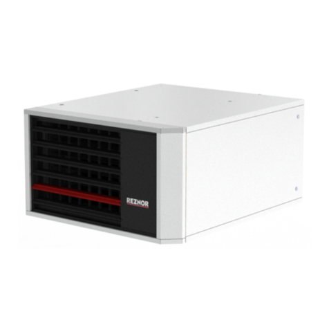
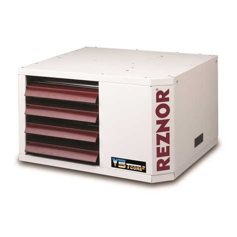
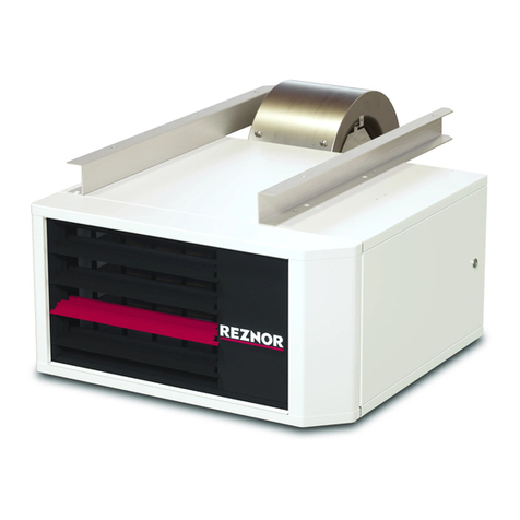
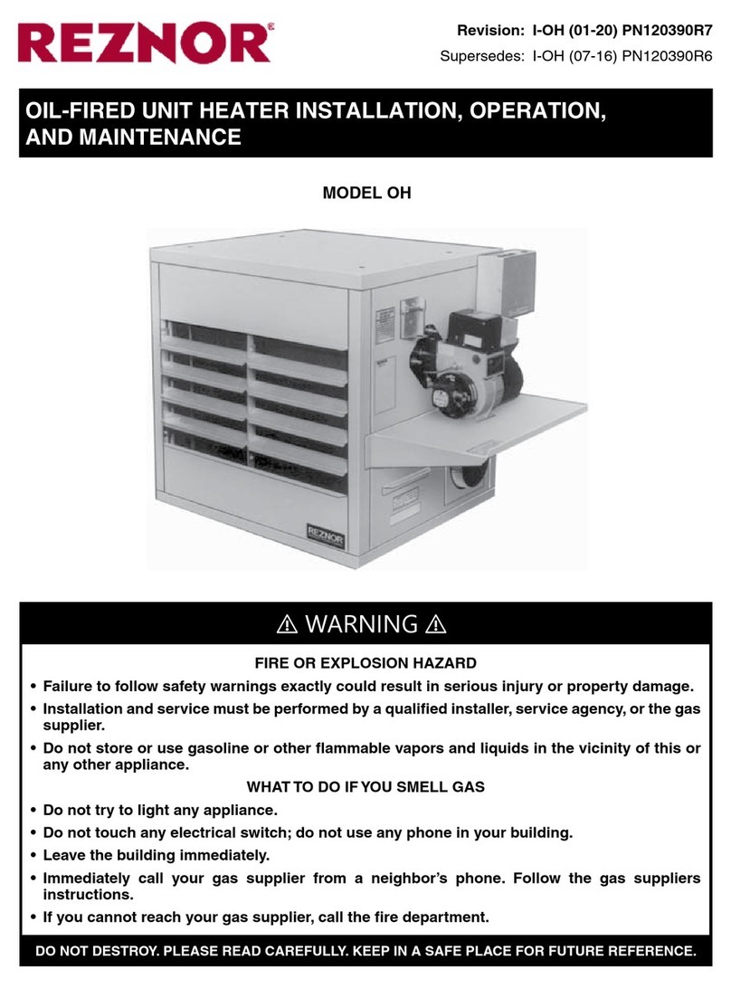
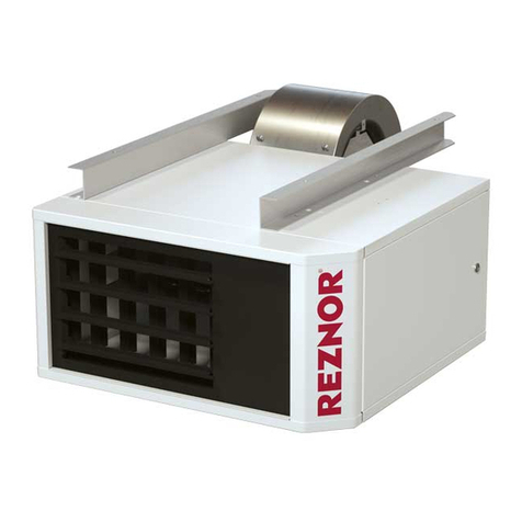
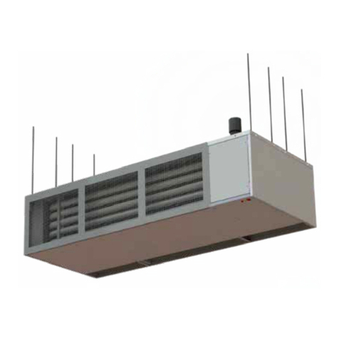
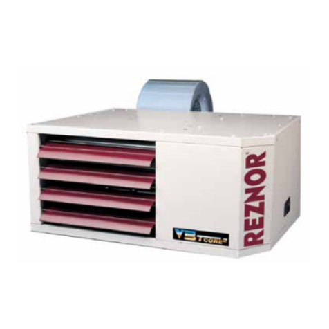
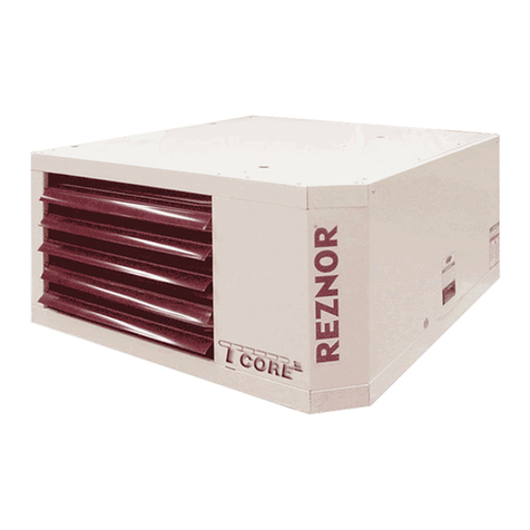
Reznor CAUA User manual

Revision: CAUA-CW4-CW16 (04-22) 166162-A
RETURN AIR FILTER CABINET INSTALLATION FOR GAS-FIRED
INDOOR HEATER
Supersedes: I-CAUA-FC (04-15) PN166162R2
OPTION CW4, CW5, CW6, CW7, CW8, CW9, CW10, CW11, CW12, CW13, CW14, CW15,
OR CW16 FOR MODEL CAUA
Table 1. Return Air Filter Cabinet Filter Applicability
Where Assembled Option 2-Inch Filter Type Unit Size
Field
CW4 Pleated
All
CW5 Permanent
CW6 Pleated or permanent*
CW7 Pleated
CW8 Pleated
150, 200
CW9 Permanent
CW10 Pleated or permanent*
CW11 Pleated or permanent *
All
CW12 Permanent
Factory
CW13 Disposable
CW14 Pleated
CW15 Permanent
CW16 Pleated or permanent*
*Field-supplied.
GENERAL INFORMATION
•These instructions are for installing an optional return air filter cabinet on a model CAUA heater.
•Refer to the installation manual provided with the heater for important safety information.
Filters
TABLE OF CONTENTS
GENERAL INFORMATION ................................................................... 1
Filters................................................................................... 1
Dimensions . . . . . . . . . . . . . . . . . . . . . . . . . . . . . . . . . . . . . . . . . . . . . . . . . . . . . . . . . . . . . . . . . . . . . . . . . . . . . . 2
COMPONENTS ............................................................................ 4
INSTALLATION ............................................................................ 6
Cut Inlet Air Opening and Drill Mounting Holes................................................... 6
Cut Inlet Air Opening and Drill Mounting Holes—Continued......................................... 8
Installation of Return Air Filter Cabinet on Side (Option CW4, CW5, or CW6)
or Rear (Option CW7, CW11, or CW12) of Heater ................................................ 8
Install Filter Cabinet with Horizontal (Rear) Inlet ............................................... 9
Install Filter Cabinet with Vertical (Top) Inlet .................................................11
Installation of Return Air Filter Cabinet on Rear or Side of Heater
(Option CW8, CW9, or CW10, Unit Size 150 or 200 Rear Inlet Only).................................12
Installation of Bottom Return Air Filter Cabinet (Option CW13, CW14, CW15, or CW16) .................14
Heater Startup...........................................................................15

2CAUA-CW4-CW16 (04-22) 166162-A
Table 2. Return Air Filter Cabinet CFM Applicability
Option
Unit Size
Option150 200 250, 300 350, 400
CFM Available
CW4
1800, 2400, 3000 2400, 3000
3000, 5000*4300, 5000 CW4
CW5 3000, 4000, 5000*4300, 5000, 6000 CW5
CW6 CW6
CW7 3000, 4000, 5000 4300, 5000 CW7
CW8 1800, 2400 2400
— —
CW8
CW9
1800, 2400, 3000 2400, 3000
CW9
CW10 CW10
CW11
3000, 4000, 5000 4300, 5000, 6000
CW11
CW12 CW12
CW13 CW13
CW14 CW14
CW15 CW15
CW16 CW16
*For 5,000 CFM on unit sizes 250 and 300, install either a cabinet on the rear of the heater or two side cabinets—one on each side.
Dimensions
GENERAL INFORMATION—CONTINUED
Filters—Continued
Figure 1. Rear Inlet Cabinet Dimensions (Refer to Table 3)
OPTIONS CW4,
CW5, CW6, CW7,
CW11, AND
CW12
OPTIONS CW8,
CW9, AND CW10

3
CAUA-CW4-CW16 (04-22) 166162-A
Table 3. Rear Inlet Cabinet Dimensions
Unit Size CW Option
Dimension*
A B C D
Inches (mm)
150, 200 4, 5, 6, 7, 11, 12 34-11/16 (881) 32 (813) 34-3/4 (883) 18 (457)
8, 9, 10 21-5/32 (537) 12-1/2 (318)
250, 300 4, 5, 6 34-11/16 (881) 32 (813)
34-3/4 (883) 18 (457)7, 11, 12 47-13/16 (1214) 45-1/8 (1143)
350, 400 4, 5, 6, 7, 11, 12 47-13/16 (1214) 45-1/8 (1143)
*See Figure 1.
Figure 2. Top Inlet Cabinet Dimensions (Refer to Table 4)
Table 4. Top Inlet Cabinet Dimensions
Unit Size CW Option
Dimension*
A B
Inches (mm)
150, 200 4, 5, 6, 7, 11, 12 34-11/16 (881) 32 (813)
250, 300 4, 5, 6 34-11/16 (881) 32 (813)
7, 11, 12 47-13/16 (1214) 45-1/8 (1143)
350, 400 4, 5, 6, 7, 11, 12 47-13/16 (1214) 45-1/8 (1143)
*See Figure 2.
Figure 3. Bottom Inlet Cabinet Dimensions
OPTIONS CW4, CW5,
CW6, CW7, CW11,
AND CW12
OPTIONS CW13, CW14, CW15, AND CW16

4CAUA-CW4-CW16 (04-22) 166162-A
COMPONENTS
Ensure that all components listed in Table 5, Table 6, Table 7, or Table 8 are available before beginning installation.
Table 5. Option CW4, CW5, and CW6 Components
Component Description
Unit Size
150, 200, 250, 300 350, 400
Option
CW4 CW5 CW6 CW4 CW5 CW6
Kit PN
166153 166154 166155 166156 166157 166158
Component PN (Quantity)*
Panel
Bottom 160925 160926
Side 160634 160634
Rear or top inlet, with duct flange 160927 164520
Top or bottom rear 160630 160631
Top rear 160632 160633
Door Assembly, with handle and latch 165033 165033
Channel Door 160635 (2) 160635 (2)
Support Filter 160636 (2) 165018 (2)
Filter, vertical inlet only 164524 (2) 164525 (2)
Channel Filter support 160923 (2) 160924 (2)
Channel assembly Filter 165035 165036
Screw Sheet metal, #10-32 ×1/2 113275 (54) 113275 (54)
Brace Corner 166151 (2) 166151 (2)
Filter** Pleated, 2 ×16 ×16 104109 (4) — 104109 (6) —
Permanent, 2 ×12 ×16 — 104103 (4) — — 104103 (6) —
*Quantity is one (1) unless otherwise indicated.
**Filters for option CW6 are field-supplied 2-inch filters.
Table 6. Option CW7, CW11, and CW12 Components
Component Description
Unit Size
150, 200 250, 300, 350, 400
Option
CW7 CW11 CW12 CW7 CW11 CW12
Kit PN
166153 166155 166154 166156 166158 166157
Component PN (Quantity)*
Panel
Bottom 160925 160926
Side 160634 160634
Rear or top inlet, with duct flange 160927 164520
Top or bottom rear 160630 160631
Top rear 160632 160633
Door Assembly, with handle and latch 165033 165033
Channel Door 160635 (2) 160635 (2)
Support Filter 160636 (2) 165018 (2)
Filter, vertical inlet only 164524 (2) 164525 (2)
Channel Filter support 160923 (2) 160924 (2)
Channel assembly Filter 165035 165036
Screw Sheet metal, #10-32 ×1/2 113275 (54) 113275 (54)
Brace Corner 166151 (2) 166151 (2)
Filter** Pleated, 2 ×16 ×16 104109 (4) — 104109 (6) —
Permanent, 2 ×12 ×16 — 104103 (4) — 104103 (6)
*Quantity is one (1) unless otherwise indicated.
**Filters for option CW11 are field-supplied 2-inch filters.

5
CAUA-CW4-CW16 (04-22) 166162-A
Table 7. Option CW8, CW9, and CW10 Components
Component Description
Unit Size
150, 200
Option
CW8 CW9 CW10
Kit PN
166159 166160 166161
Component PN (Quantity)*
Panel
Top 164537
Side 164536
Rear inlet, with duct flange 164533
Bottom 164537
Door Assembly, with handle and latch 166148
Channel Door 164535
Support Filter 164704 (2)
Channel Filter support 164532 (2)
Channel assembly Filter 166147
Screw Sheet metal, #10-32 ×1/2 113275 (20)
Filter** Pleated, 2 ×12 ×32 114324 (2) —
Permanent, 2 ×12 ×16 — 114325 (4) —
*Quantity is one (1) unless otherwise indicated.
**Filters for option CW10 are field-supplied 2-inch filters.
Table 8. Option CW13, CW14, CW15, and CW16 Components
Component Description
Unit Size
150, 200 250, 300 350, 400
Option
CW13 CW14 CW15 CW16 CW13 CW14 CW15 CW16 CW13 CW14 CW15 CW16
Kit PN
195165 195154 195157 195160 195166 195155 195158 195161 195167 195156 195159 195162
Component PN (Quantity)*
Panel Side 194686 (2) 194675 (2) 194675 (2)
Rear 194677 194662 194662
Door cover Top 194686 194672 (2) 194672 (2)
Door Assembly 194938 194939 (2) 194939 (2)
Filter**
Disposable,
2 ×16 ×16
104101
(6) —104101
(8) —104101
(12) —
Pleated disposable,
2 ×16 ×16 —104109
(6) — — 104109
(8) — — 104109
(12) —
Permanent aluminum,
2 ×16 ×16 —104103
(6) — — 104103
(8) — — 104103
(12) —
Filter rack Assembly, single 194916 (2) 194916 (4) 194917 (4)
Assembly, double 194914 (2) 194914 (2) 194915 (2)
Blockoff Filter 195164 (3) 195164 (4) 195164 (4)
*Quantity is one (1) unless otherwise indicated.
**Filters for option CW16 are field-supplied 2-inch filters.

6CAUA-CW4-CW16 (04-22) 166162-A
INSTALLATION
NOTE: Not all screw holes will be used.
Cut Inlet Air Opening and Drill Mounting Holes
1. If heater is installed, turn OFF gas and electric power and disconnect any return air ductwork.
⚠ WARNING ⚠
Cut edges of metal cabinets are sharp.
2. Locate four embosses (see Figure 4) in metal panel where filter cabinet is to connect to heater. Embosses are
corner indicators for inlet air opening.
Figure 4. Embosses
CW4, CW5, CW6 CW7, CW11, CW12
CW8, CW9, CW10 (REAR)CW8, CW9, CW10 (SIDE)
CW13, CW14, CW15, CW16 (BOTTOM)
150/200: 19" (483mm)
250/300: 16" (406mm)
350/400: 32" (813mm)
150/200: 34" (864mm)
250/300: 46" (1168mm)
350/400: 46" (1168mm)

7
CAUA-CW4-CW16 (04-22) 166162-A
⚠ DANGER ⚠
When cutting the inlet air opening for options CW13,CW14,CW15, and CW16,bottom filter cabinets,
provide adequate support for the unit.
NOTE: When cutting the opening in the bottom of the unit, the unit will have to be tipped. Provide
adequate support for the unit during this process. If the installation includes an optional cooling
coil and/or a discharge plenum, cut inlet air opening before adding these accessories.
3. Carefully cut straight lines between embosses to create inlet opening using tin snips or aviation shears.
NOTE: Mounting hole dimensions for options CW8, CW9, and CW10 are different for the door and
heater ends of the filter cabinet. Mounting holes are not required for options CW13, CW14, CW15,
and CW16, bottom filter cabinets with bottom duct openings.
4. For option CW4, CW5, CW6, CW7, CW8, CW9, CW10, CW11, or CW12, mark and drill four 1/8-inch holes above
inlet opening as shown in Figure 5.
Figure 5. Mounting Holes and Dimensions (Refer to Table 9)
CW4, CW5, CW6 CW7, CW11, CW12
CW8, CW9, CW10

8CAUA-CW4-CW16 (04-22) 166162-A
Table 9. Inlet Air Opening Dimensions
Option Dimension*
Unit Size
150, 200 250, 300 350, 400
Inches (mm)
CW4, CW5, CW6 A 8 (203) 9 (229)
E (number of holes) 5 6
CW7, CW11, CW12
B 2-15/32 (63) 1-29/32 (48)
C 3 (76) 2-1/2 (64)
D 8 (203) 9 (229)
E (number of holes) 5 6
CW8, CW9, CW10
F (door end) Side panel: 1-13/16 (46)
—
Rear panel: 2-15/32 (63)
G (heater end) Side panel: 1-11/32 (34)
Rear panel: 2 (51)
CW13, CW14, CW15, CW16
A 34 (864) 46 (1168) 46 (1168)
B 4-5/8 (117) 4-3/4 (121) 4-7/8 (124)
C 19 (483) 16 (406) 32 (813)
*See Figure 5.
Installation of Return Air Filter Cabinet on Side (Option CW4, CW5, or CW6) or Rear (Option
CW7, CW11, or CW12) of Heater
NOTE: Options CW4, CW5, CW6, CW7, CW11, and CW12 are shipped separately for field-assembly
and installation. The cabinets are assembled as they are installed.
See possible configurations shown in Figure 6 and Figure 7. Return air filter cabinet is shaded gray. Refer to Table
5or Table 6 for option package components.
INSTALLATION—CONTINUED
Cut Inlet Air Opening and Drill Mounting Holes—Continued
Figure 6. Option CW4, CW5, and CW6 Configurations
Figure 7. Option CW7, CW11, and CW12 Configuration
INSTALLATION ON EITHER SIDE
(ALL UNIT SIZES)
INSTALLATION ON BOTH SIDES
(UNIT SIZES 250 AND 300)
INSTALLATION ON REAR (ALL UNIT SIZES)

9
CAUA-CW4-CW16 (04-22) 166162-A
Install Filter Cabinet with Horizontal (Rear) Inlet
1. Assemble two filter support assemblies using two filter supports, two filter support channels, and sheet metal
screws as shown in Figure 8.
Figure 8. Assemble Filter Supports
2. Install two door channels, two filter support assemblies, and bottom panel as shown in Figure 9:
a. Install door channels as shown and secure using sheet metal screws.
b. Remove existing screws from along bottom edge of heater cabinet. Position bottom panel against heater cabinet
and first filter support assembly on top of bottom panel (channel up) as shown and secure bottom panel and
filter support assembly using existing screws.
c. Remove existing screws above cutout area, position second filter support assembly over holes (channel down)
as shown, and secure filter support assembly to heater cabinet using existing screws.
FILTER SUPPORT
FILTER SUPPORT CHANNEL
SHEET METAL SCREW
Figure 9. Install Bottom Panel and Filter Support Assemblies
NOTE: Install a side panel on one end of the filter cabinet and a door assembly on the other end
of the filter cabinet.
3. Install side panel, rear inlet panel, and filter channel assembly as shown in Figure 10:
a. Secure side panel to door channel installed in step 2a using sheet metal screws. Secure rear inlet panel to
side panel and to bottom panel installed in step 2b using sheet metal screws.
b. Secure filter channel assembly to rear inlet panel using sheet metal screws.
DOOR CHANNEL
SHEET METAL SCREWS
FILTER
SUPPORT
ASSEMBLY BOTTOM PANEL
EXISTING SCREWS
DOOR CHANNEL
EXISTING SCREWS

10 CAUA-CW4-CW16 (04-22) 166162-A
INSTALLATION—CONTINUED
Installation of Return Air Filter Cabinet on Side (Option CW4, CW5, or CW6) or Rear (Option
CW7, CW11, or CW12) of Heater—Continued
Install Filter Cabinet with Horizontal (Rear) Inlet—Continued
Figure 10. Install Side and Rear Inlet Panels and Filter Channel Assembly
4. Install rear top panel, top panel, and corner braces and secure filter cabinet to heater cabinet as shown in Figure 11:
a. Secure rear top panel to side panel and rear inlet panel installed in step 3a using sheet metal screws. Secure
top panel to rear inlet panel and to heater cabinet using sheet metal screws.
b. For structural support, install corner braces—one in bottom outer corner on door end of filter cabinet and one
in top outer corner. Secure braces using sheet metal screw.
SIDE PANEL
REAR INLET PANEL
FILTER CHANNEL ASSEMBLY
SHEET METAL SCREW
S
SHEET METAL SCREWS
Figure 11. Install Horizontal Inlet Filter Cabinet on Heater
5. Slide filters into filter rack channels.
6. Install door assembly on open end of filter cabinet and secure using sheet metal screws. Fasten door latches.
7. Connect ductwork (refer to Dimensions section for duct flange dimensions).
CORNER
BRACES
SHEET METAL
SCREWS
SHEET METAL SCREWS
TOP PANEL
REAR
TOP
PANEL
SHEET METAL SCREWS

11
CAUA-CW4-CW16 (04-22) 166162-A
Install Filter Cabinet with Vertical (Top) Inlet
1. Install two door channels, vertical filter support, and bottom panel as shown in Figure 12:
a. Install door channels as shown and secure using sheet metal screws.
b. Remove existing screws above cutout area, position vertical filter support over holes as shown, and secure
support to heater cabinet using existing screws.
c. Remove existing screws from along bottom edge of heater cabinet. Position bottom panel against heater cabinet
and filter support on top of bottom panel as shown and secure both to heater cabinet using existing screws.
Figure 12. Install Bottom Panel and Vertical Filter Support
NOTE: Install a side panel on one end of the filter cabinet and a door assembly on the other end
of the filter cabinet.
2. Install side panel and bottom rear panel as shown in Figure 13:
a. Secure side panel to door channel installed in step 1a using sheet metal screws.
b. Secure bottom rear panel to side panel and to bottom panel installed in step 1c using sheet metal screws.
DOOR CHANNEL
SHEET METAL SCREWS
VERTICAL
FILTER
SUPPORT BOTTOM PANEL
EXISTING SCREWS
DOOR CHANNEL
EXISTING SCREWS
Figure 13. Install Side and Bottom Rear Panels
SIDE PANEL
BOTTOM REAR PANEL
SHEET METAL SCREW
S
SHEET METAL SCREWS

12 CAUA-CW4-CW16 (04-22) 166162-A
INSTALLATION—CONTINUED
Installation of Return Air Filter Cabinet on Side (Option CW4, CW5, or CW6) or Rear (Option
CW7, CW11, or CW12) of Heater—Continued
Install Filter Cabinet with Vertical (Top) Inlet—Continued
3. Install rear top panel, top inlet panel, filter channel assembly, and corner braces and secure filter cabinet to heater
cabinet as shown in Figure 14:
a. Secure rear top panel to side panel and to bottom rear panel installed in step 2b using sheet metal screws.
b. Secure top inlet panel to rear top panel and to heater cabinet using sheet metal screws.
c. Install vertical filter support as shown and secure support to top rear panel using existing screws.
d. Position filter channel assembly across inlet opening as shown and secure using sheet metal screws.
e. For structural support, install corner braces—one in bottom outer corner on door end of filter cabinet and one
in top outer corner. Secure braces using sheet metal screw.
Figure 14. Install Vertical Inlet Filter Cabinet on Heater
4. Slide filters into filter rack channels.
5. Install door assembly on open end of filter cabinet and secure using sheet metal screws. Fasten door latches.
6. Connect ductwork (refer to Dimensions section for duct flange dimensions).
Installation of Return Air Filter Cabinet on Rear or Side of Heater (Option CW8, CW9, or CW10,
Unit Size 150 or 200 Rear Inlet Only)
NOTE: Options CW8, CW9, and CW10 are shipped separately for field-assembly and installation.
The cabinets are assembled as they are installed.
See possible configurations shown in Figure 15. Return air filter cabinet is shaded gray. Refer to Table 7 for option
package components.
REAR
TOP
PANEL
TOP
INLET
PANEL
FILTER
CHANNEL
ASSEMBLY
SHEET
METAL
SCREWS
CORNER
BRACE
VERTICAL
FILTER
SUPPORT
CORNER
BRACE
SHEET
METAL
SCREWS
INSTALLATION ON EITHER SIDE
(UNIT SIZES 150 AND 200)
INSTALLATION ON REAR
(UNIT SIZES 150 AND 200)
Figure 15. Option CW8, CW9, and CW10 Configurations

13
CAUA-CW4-CW16 (04-22) 166162-A
1. Install door channel, bottom panel, filter support, and filter support channel as shown in Figure 16:
a. Install door channel as shown and secure using sheet metal screws.
b. Remove existing screws from along bottom edge of heater cabinet. Position bottom panel against heater
cabinet and as shown and secure bottom panel to heater cabinet using existing screws.
c. Position filter support channel (channel up) as shown and secure to filter support using sheet metal screws.
Figure 16. Install Door Channel, Bottom Panel, Filter Support, and Filter Support Channel
NOTE: Install a side panel on one end of the filter cabinet and a door assembly on the other end
of the filter cabinet.
2. Install side panel, rear inlet panel, and filter channel assembly as shown in Figure 17:
a. Secure side panel to bottom panel installed in step 1b using sheet metal screws. Secure rear inlet panel to
side panel and bottom panel using sheet metal screws.
b. Position filter channel assembly across inlet opening as shown and secure using sheet metal screws.
Figure 17. Install Side Panel, Rear Inlet Panel, and Filter Channel Assembly
3. Install top panel, filter support channel, and filter support and secure filter cabinet to heater cabinet as shown in
Figure 18:
a. Remove existing screws above cutout area, position top panel and filter support as shown, and secure panel
and support to heater cabinet using existing screws.
b. Position filter support channel (channel down) as shown and secure to filter support using sheet metal screws.
DOOR
CHANNEL
BOTTOM PANEL
FILTER SUPPORT
CHANNEL
FILTER SUPPORT
SHEET METAL
SCREWS
SHEET METAL
SCREWS
EXISTING SCREWS
FILTER CHANNEL
ASSEMBLY
SIDE PANEL
REAR INLET PANEL
SHEET METAL SCREW
S

14 CAUA-CW4-CW16 (04-22) 166162-A
INSTALLATION—CONTINUED
Installation of Return Air Filter Cabinet on Rear or Side of Heater (Option CW8, CW9, or CW10,
Unit Size 150 or 200 Rear Inlet Only)—Continued
Figure 18. Install Rear Inlet Filter Cabinet on Heater
4. Slide filters into filter rack channels.
5. Install door assembly on open end of filter cabinet and secure using sheet metal screws. Fasten door latches.
6. Connect ductwork (refer to Dimensions section for duct flange dimensions).
Installation of Bottom Return Air Filter Cabinet (Option CW13, CW14, CW15, or CW16)
NOTE: Options CW13, CW14, CW15, and CW16, bottom return air filter cabinets with bottom duct
openings, are shipped factory-assembly for field-installation. The bottom return air filter cabinet
supports the heater and provides a filtered path for vertical return air.
See configuration shown in Figure 19. Return air filter cabinet is shaded gray.
SHEET METAL SCREWS
FILTER SUPPORT CHANNE
L
FILTER
SUPPORT
CHANNEL
TOP PANEL
EXISTING
SCREWS
Figure 19. Option CW13, CW14, CW15, and CW16 Configuration
NOTE: Ensure that inlet air opening has been cut in bottom of the heater before it is placed on
the filter cabinet.The cabinet's filter access doors may face either to the front or rear of the heater.
1. Position filter cabinet so that sufficient clearance on filter access side is allowed. Secure cabinet.
2. Install heater, setting it on filter cabinet, which is designed so that there is no mechanical connection between
cabinet and heater.
3. Connect return air duct to duct flange on bottom of filter cabinet. Duct opening dimensions are shown in Figure
20 and listed in Table 10.
INSTALLATION ON BOTTOM
(ALL UNIT SIZES)

15
CAUA-CW4-CW16 (04-22) 166162-A
Figure 20. Bottom Return Air Filter Cabinet Duct Opening Dimensions (Refer to Table 10)
Table 10. Bottom Return Air Filter Cabinet Duct Opening Dimensions
Dimension*
Unit Size
150, 200 250, 300 350, 400
Inches (mm)
A 25-1/2 (648) 37-1/2 (953)
B 32 (813) 46 (1168)
*See Figure 20.
Heater Startup
When heater and ductwork installation is complete, turn ON electric power and gas, start up heater, and check for
proper operation.
Other manuals for CAUA
7
Table of contents
Other Reznor Heater manuals

Reznor
Reznor LDAP Owner's manual

Reznor
Reznor AB175-2 User manual

Reznor
Reznor OH User manual

Reznor
Reznor EBHB User manual

Reznor
Reznor RA 140 User manual

Reznor
Reznor 12 Guide

Reznor
Reznor RIH Series Owner's manual

Reznor
Reznor Euro-T 2530D User manual

Reznor
Reznor V3 Series Guide

Reznor
Reznor ULSA 035(EC) User manual
Popular Heater manuals by other brands

Pro Breeze
Pro Breeze PB-H06 instruction manual

Empire Heating Systems
Empire Heating Systems SR-6W-1 Installation instructions and owner's manual

VOGEL&NOOT
VOGEL&NOOT NERO Assembly and operating manual

Broan
Broan QTX100HL Specification sheet

Mark
Mark EASYAIR 100 Technical manual

Calix
Calix M7T 734 Assembly instructions