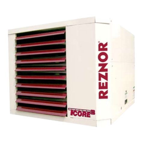
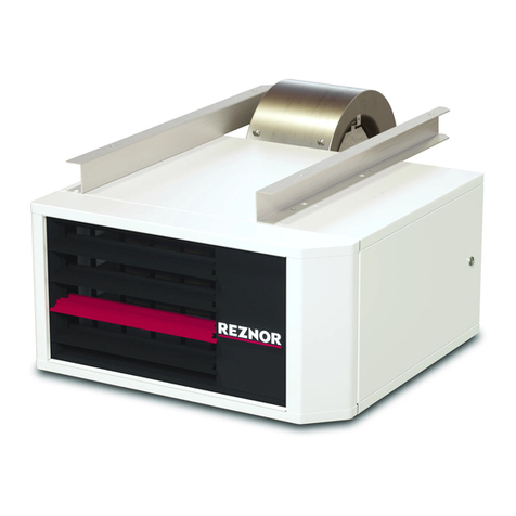
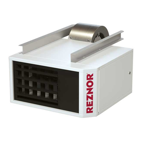
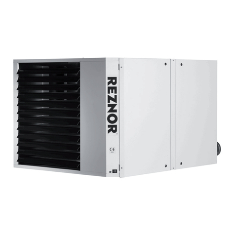
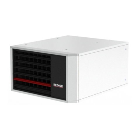
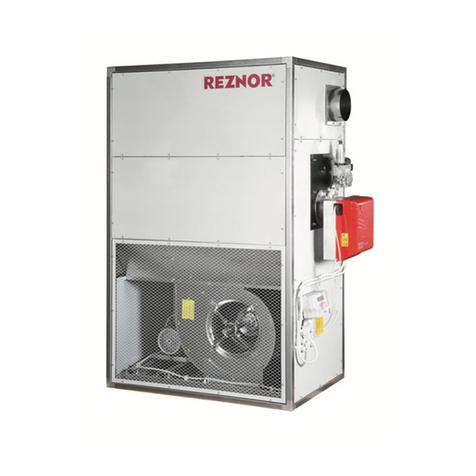
Reznor ULSA 035(EC) User manual

1701ULSA(EC)--EN, p. 1/30
Pleasereadthisdocumentcarefullybeforecommencingtheinstallationandleaveitwith
theuserorattachedtotheapplianceorgasservicemeterafterinstallation!
1701ULSA(EC)‐‐EN
Condensinglow‐emissiongas‐firedairheater
ULSA
025(EC),035(EC),050(EC),
075(EC),100(EC)
ThisappliancemeetsthefollowingECDirectives
DIR2009/142/EC:GAD
DIR2014/30/EU:EMC
DIR2014/35/EU:LVD
DIR2006/42/EC:MD
INSTALLATION–COMMISSIONING–SERVICING–USER‐INSTRUCTIONS
Appliesto:
Belarus,Bulgaria,China,CzechRepublic,Croatia,Cyprus,Denmark,Estonia,Finland,Greece,Hungary,Iceland,
Latvia,Lithuania,Montenegro,NewZealand,Norway,Poland,Portugal,Romania,RussianFederation,Serbia,
Slovakia,Slovenia,SouthAfrica,Spain,Sweden,Turkey,Ukraine
ATTENTION
Themanufacturerdoesnottakeanyresponsibilityintheeventofnon‐observanceofthe
regulationconcerningtheconnectionoftheapparatuscausingaharmfuloperation
possiblyresultingindamagetotheapparatusand/orenvironmentinwhichtheunitis
installed.
Subjecttomodifications
size050

1701ULSA(EC)--EN, p. 2/30
TABLEOFCONTENTS
1 Hazardintensitylevels2
2 General3
Warnings3
General4
Warranty4
Uncrating&preparation4
Heaterlocation5
3 Technicaldata6
4 Dimensions&clearances8
5 Internallay‐out10
6Installing11
7 Airsupply&fluesystems12
8 Condensationdrainpipeconnection16
9 Gasconnection/Gassupply17
10Electricalconnections19
11Commissioning,lighting&operation21
12Maintenance23
13Faultfinding25
14Sparepartslist27
15Userinstructions27
16Declarationofconformity29
1.HAZARDINTENSITYLEVELS
DANGER
Failuretocomplywillresultinseverepersonalinjuryordeathand/or
propertydamage.
WARNING
Failuretocomplycouldresultinseverepersonalinjuryordeathand/or
propertydamage.
CAUTION
Failuretocomplycouldresultinminorpersonalinjuryand/orproperty
damage.

1701ULSA(EC)--EN, p. 3/30
2.GENERAL
2.1WARNINGS
WARNINGS
Foryoursafety,ifyousmellgas:
Donottrytolightanyappliance
Donottouchanyelectricalswitch,donotuseanyphoneinyourbuilding
Evacuateallpersonnel
Contactyourgassupplierimmediately
Donotstoreorusepetrolorotherflammablevapoursandliquidsinthevicinityofthe
appliance.
Improperinstallation,adjustment,alteration,serviceormaintenancecancause
propertydamage,injuryordeath.Readtheinstallation,operationandmaintenance
instructionsthoroughlybeforeinstallingorservicingthisequipment.
Donotusethisapplianceifanyparthasbeenimmersedinwater.Immediatelycalla
qualifiedservicetechniciantoinspecttheapplianceandreplaceanygascontrolthat
hasbeenimmersedinwater.
Thisapplianceisnotintendedforusebypersons(includingchildren)withreduced
sensoryormentalcapacitiesorlackofexperienceandknowledgeunlesstheyhave
beengivensupervisionorinstructionsconcerninguseoftheappliancebyaperson
responsiblefortheirsafety.
Childrenshouldbesupervisedtoensurethattheydonotplaywiththeappliance.
Shouldoverheatingoccurorthegassupplyfailstoshutoff,shutoffthemanualgas
valvetotheappliancebeforeshuttingofftheelectricalsupply.
Gas‐firedappliancesarenotdesignedforuseinhazardousatmospherescontaining
flammablevapoursorcombustibledust,inatmospherescontainingchlorinatedor
halogenatedhydrocarbonsorinapplianceswithairbornesiliconesubstances.
Themanualshouldbekeptinasafeplaceforfuturereference.
Unauthorisedmodificationofthisapplianceordeparturefromuseinthemanner,for
whichitwasintendedbythemanufacturerorinstalledinamannercontrarytothese
instructions,mayconstituteahazardandjeopardizeallwarranties.
Deviationsshouldonlybecarriedoutafterformalconsenthasbeenobtainedfrom
themanufacturer.
Useonlyfactory‐authorizedpartswhenreplacementisrequired.
Incaseofpersistingproblems,contactyourdistributor

1701ULSA(EC)--EN, p. 4/30
2.2GENERAL
Theinstructionsinthismanualapplytothecondensinggas‐firedairheatermodelULSA/ULSAEC.Allmodels
andsizesareavailableforusewitheithernatural,propaneorbutanegaswithinoperatingtemperatures
between‐15°Cand40°C.
Theseheatersaredesignedforuseindomestic,industrialandcommercialpremises,suitableonlyforindoor
installation
Thetypeofgas,theinputrateandtheelectricalsupplyrequirementsareshownontheheaterratingplate.
Theinstructionsareonlyvalidforthecountryofuseindicatedontheappliance.Ifnotcorrectcontactyour
supplier.
Installationshouldbedonebyasuitablyqualifiedinstallerinaccordancewiththeseinstructionsandwithall
rulesinforce.
Theinstallationmanualisshippedwiththeheater.Verifythattheliteratureiscorrectfortheheaterbeing
installed.Ifthemanualisincorrectfortheheater,contactthesupplierbeforebeginninginstallation.
Ensuretheenvironmentinwhichtheairheaterwillbeinstalledwillnotcreateahazardi.e.whereexcessive
dust,flammableorcorrosivesubstancesand/orvapoursandcombustiblematerialsmaybepresent.
2.3WARRANTY
Warrantyisvoidif:
Heatersareusedinatmospherescontainingflammablevapoursoratmospherescontaining
chlorinatedorhalogenatedhydrocarbonsoranycontaminant(silicone,aluminiumoxide,etc...).
Theinstallationisnotinaccordancewiththeseinstructions.
Wiringisnotinaccordancewiththediagramfurnishedwiththeheater.
Unitisinstalledwithoutproperclearancetocombustiblematerialsorwithoutproperventilation
andairforcombustion.
Airthroughputisnotadjustedwithintherangespecifiedontheratingplate.
2.4UNCRATING&PREPARATION
Theunitwastestoperatedandinspectedatthefactorypriortocratingandwasinproperoperatingcondition.
Iftheheaterhasincurreddamageinshipment,documentthedamagewiththetransportcompanyand
contactyoursupplier.Beforeinstallationcheckthattheapplianceasdescribedonthepackaginglabelisin
accordancewiththecorrecttypeandmodelasspecifiedonthedataplateandcomplieswithyourcustomer
order.Afterunpackingtheappliance,leaveitfastenedtoanybasepackingfortransportationuntilithasbeen
suspendedoruntiljustbeforebasemounting.Thisaffordsprotectiontotheunderside.
Checktheratingplatetodetermineiftheheaterisappropriatefortheintendedinstallation.
Readthemanualthoroughlyandbecomefamiliarwiththeinstallationrequirementsofyourheater.Ifyoudo
nothaveknowledgeoflocalrequirements,checkwiththegassupplierandanyotherlocalagenciesthatmight
haverequirementsconcerningthisinstallation.
Beforebeginningmakepreparationsfornecessarysupplies,toolsandmanpower.Iftheinstallationincludes
optionalparts,installtheseoptionsbeforetheheaterissuspended.Followtheinstructionsincludedinthe
optionpackage.

1701ULSA(EC)--EN, p. 5/30
2.5HEATERLOCATION
AttentionFluerequirementsmayaffectlocation.Consultsection 7beforemakingafinaldetermination.
Usetheminimumclearancesasillustratedinfigure2andthethrowdatamentionedintable1(Technical
Data)todefinewheretolocatetheheater.
Alsorespecttherecommendedminimumheightasgivenintable1.
Forbestresults,theheatershouldbeplacedwithcertainrulesinmind.Alwaysensurethatminimum
clearancesaremaintained.Locatingaunitheaterabovethemaximumrecommendedheightcanresultin
significantairstratification.Whenpossible,heatersshouldbearrangedtoblowtowardoralongexposedwall
surfaces.
Suspendedheatersaremosteffectivewhenlocatedasclosetotheworkingzoneaspossible,butcareshould
beexercisedtoavoiddirectingthedischargedairdirectlyontotheroomoccupants.
Partitions,columns,countersorotherobstructionsshouldbetakenintoconsiderationwhenlocatingtheunit
heatersothataminimumquantityofairflowwillbedeflectedbysuchobstacles.
Whenunitsarelocatedinthecentreofthespacetobeheated,theairshouldbedischargedtowardthe
exposedwalls.Inlargeareas,unitsshouldbelocatedtodischargeairalongexposedwallswithextraunits
providedtodischargeairtowardsthecentreofthearea.Foroptimumresultsheatersarebestusedin
conjunctionwithrecirculatingairfanssuspendedathighlevel.
Atthosepointswhereinfiltrationofcoldairisexcessive,suchasentrancedoors...itisdesirabletolocatethe
unitsothatitwilldischargedirectlytowardsthesourceofcoldair,typicallyfromadistanceof4.5mto6mor
installadownflownunitoverthedooropening.
WARNING
Iftouched,theventpipeand
internalheatersurfacesthatare
accessiblefromoutsidetheheater
willcauseburns.Suspendthe
heatersothatthesecomponents
cannotbetouched!
CAUTION
Donotlocatethe
heaterwhereitmay
beexposedtowater.
Attention
Hazardsof
chlorine
applyto
the
locationof
the
combustion
airinlet
Thepresenceofchlorinevapoursinthecombustionairofgas‐firedheatingequipmentpresents
apotentialcorrosionhazardCareshouldbetakentoseparatethesevapoursfromthe
combustionprocess.
Thismaybedonebywiselocationoftheunitflueandcombustionairterminalswithregardto
exhaustersorprevailingwinddirections.
Chlorineisheavierthanair.Keepthisfactinmindwhendetermininginstallationlocationofthe
heaterinrelationtobuildingexhaustsystems.
Wherechlorinevapoursareprevalent,heaterswithspecialgrade316AISIstainlesssteelheat
exchangersarerecommended.

1701ULSA(EC)--EN, p. 6/30
3.TECHNICALDATA
Table1b
ULSA/ULSA EC 025 035 050 075 100
Gas category Cat.
Comb. air & flue, type B instal (1)
Comb. air & flue, type c instal (1)
Maximum heat input (Hs) kW 28,3 37,0 56,0 78,4 106,3
Maximum heat input (Hi) kW 25,5 33,3 50,4 70,6 95,7
Minimum heat input (Hs) kW 5,7 7,2 11,4 15,9 20,9
Minimum heat input (Hi) kW 5,2 6,5 10,3 14,3 18,9
Maximum heat output kW 25,0 32,7 49,4 69,2 93,8
Minimum heat output kW 5,5 7,0 11,0 15,3 20,2
% 98,30 98,00 98,60 98,60 98,60
% 109,20 108,80 108,70 106,50 108,90
NatgasG20(H)vol%8,438,428,448,428,42
PropG31 vol%9,819,819,819,809,80
Propane restrictor diameter mm 3,4 6 6 6 6
NatgasG20(H)m³/h2,593,395,077,279,76
Prop G31 kg/h 1,99 2,6 3,93 5,51 7,47
NatgasG20(H)m³/h0,550,691,091,522,00
Prop G31 kg/h 0,4 0,51 0,8 1,12 1,47
Nat gas G20 (H) mbar
Prop G31 mbar
Air volume (15°C) m³/h 2900 3700 5600 7900 10500
Temperature rise at max load K2526262626
Horizontal throw (4) m 20 23 30 30 36
Max sound pressure level Lp (5) dB(A) 44 49
52 47 58
Min sound pressure level Lp (5) dB(A) 38 34
35 35 40
Noise free field conditions(max) dB(A) 37 42
45 40 51
Noise free field conditions (min) dB(A) 31 27
28 28 33
Maximum absorbed power W 200 300 500 600 1.240
Gas connection (2)
Electrical connection mm 80 80 80 100 100
Condensation connection/outlet
Condensate quantity l/h 1,3 1,5 2 2,5 3,5
Recommended mounting heigth (3) m3 3,53,5 4 4
Weight kg 120 129 147 199 231
Protection grade IP
Revolutions per minute rpm 950 1260 1340 820 1400
1/2" G 3/4" G
See table 1b
B22p
C12, C32, C42, C52, C62, C82
Max thermal efficiency at max heat input (G20)
Max thermal efficiency at min heat input (G20)
CO
2
gas at max heat input
230/240 V 1N50Hz
Connection diameter for flue gas and combustion air
32
IP 20
Gas consumption at maximum heat input
Gas consumption at minimum heat input
Inlet pressures See table 1b
See table 1b
(1)Gas Appliance Classifications for Approved Venting Methods based on CEN-report CR1749:2001
(2)Gasconnectionsizeisnotnecessarilythesupplylinesize.Thereisadifferencebetweenthegasconnectiondiameterandthediameterofthesupplyline.
Alwaysusethemostadequatediaofthesupplylinetominimizethepressuredropthroughthegaspipes–ifnecessaryreducethediameterofthesupplylineat
theinletoftheunit.
(3)Heightfromthefloortobottomsurfaceofheater.Thesearerecommendationsonly.Positioningofunitheatersforproperperformanceisapplication
dependent.Operationisaffectedbyotherairmovingequipmentinthespace,obstructionstotheairflow,draughtsand/orcloseproximitytodoorsor
windows,etc…Careshouldbetakentoavoidmountingtheheatersabovetheserecommendations,unlessdownturnnozzleoptionsareused,assignificant
stratificationmayoccurresultinginpoorfloorcoverageandhigherenergylossesthroughtheroofstructure.
(4)Isothermalconditionsat20°Cambientairtemperature,dischargelouvrezerodeflection,v=0,5m/s.
(5)SoundpressurelevelindB(A):measuredat5metersfromtheunitwithA=160m²&Q=2
1701ULSA(EC)--EN, p. 7/30
Table1b:Gascategory&inletpressures
country
gascat
G20
inletpressure
(mm)
gascat
G31
inletpressure
(mm)
Belarus I2H 20 I3P 37
Bulgaria I2H 20 I3P 37
China I2H 20 I3P 37
CzechRepublic I2H 20 I3P 37
Croatia I2H 20 I3P 37
Cyprus I2H 20 I3B/P 30
Denmark I2H 20 I3B/P 30
Estonia I2H 20 I3B/P 30
Finland I2H 20 I3B/P 30
Greece I2H 20 I3P 37
Hungary I2H 20 I3B/P 50
Iceland I2H 20 I3P 37
latvia I2H 20 I3P 37
Lithuania I2H 20 I3P 37
Montenegro I2H 20 I3P 37
NewZeeland I2H 20 I3P 37
Norway I2H 20 I3B/P 30
Poland I2E 20 I3B/P 30
Portugal I2H 20 I3P 37
Romania I2E 20 I3B/P 30
RussianFederation I2H 20 I3P 37
Serbia I2H 20 I3P 37
Slovakia I2H 20 I3P 37
Slovenia I2H 20 I3P 37
SouthAfri ca I 2H 20 I 3P 37
Spain I2H 20 I3P 37
Sweden I2H 20 I3B/P 30
Turkey I2H 20 I3P 37
Ukraine I2H 20 I3P 37

1701ULSA(EC)--EN, p. 8/30
4.DIMENSIONS&CLEARANCES
4.1DIMENSIONS
Figure1a:ULSA/ULSAEC025,035,050&075(alldimensionsinmm,tolerance3mm)
1. Combustion air inlet (D) 4. Electrical connections
2. Flue connection (D) 5. Service panel
3. External gas connection (C) 6. Condensate drain
ULSA/ULSAEC A B C DE F I J K L M
025 738 1217 1/2"G 80 82 405 55 449 135 311 120
035 738 1217 1/2"G 80 82 405 55 449 135 311 120
050 865 1216 3/4"G 80 74 531 50 576 140 311 120
075 1177 1274 3/4"G 100 129 760 78 860 143 294 140

1701ULSA(EC)--EN, p. 9/30
Figure1b:ULSA/ULSAEC100(alldimensionsinmm,tolerance3mm)
1. Combustion air inlet ( 100mm) 4. Electrical connections
2. Flue connection ( 100mm) 5. Service panel
3. External gas connection (3/4”G) 6. Condensate drain

1701ULSA(EC)--EN, p. 10/30
4.2CLEARANCES
Figure2:
ULSA/ULSA EC X Y Z(*) U V
025 400 100 100 100 820
035 400 100 100 100 820
050 400 100 100 100 820
075 500 100 100 100 820
100 500 100 100 100 820
(*)Heaterscanbemountedonsuitablenon‐combustiblesupports.
5.INTERNALLAYOUT
Figure3:
1Metalmeshburner
2Zeropressure
regulator
3Venturi
4Differential
pressureswitch
5Burnercontroller
6Fluegasextraction
fan
7Inspectionwindow
+ignitor+ionisation
electrode
8LimitcontrolLC3
9LimitcontrolLC1
9 8

1701ULSA(EC)--EN, p. 11/30
6INSTALLING
WARNING
Checkthesupportingstructuretoverifythatithassufficientload‐carryingcapacityto
supporttheunitweight.
Suspendtheheateronlyfromthethreadednutinserts.Donotsuspendfromtheheater
cabinetpanels.
Donotplaceoraddadditionalweighttothesuspendedheater.
Thelocationwheretheairheateristobeinstalledmustprovidesufficientspacearoundtheheaterfor
servicingandclearancesforsafety(seefigure2).
Whentheunitisliftedforsuspension,leavetheunitonthepallet.Beforehangingverifythatallscrews
originallyusedtofixtheshippingsupportsarere‐screwedintothecabinet.
Ensurethattheheaterisinstalledinalevelplaneandvibrationfree.
Theairheatermustbefastenedsecurelytoanybasemountingarrangement.
Theheaterissuppliedwithfourpointsuspension.Allpointsmustbeused.Threadednutinsertsareprovided
oneachsideofthetopoftheheater.Seefigure4.
Aftersuspensiontheairheatershouldberigidsoastoavoidplacingastrainonthefluesystem,gasservices,
electricalwiringandductwork.1”BSPmountingcapnutsareoptional.
IncaseofatypeCinstallation,thedistancebetweenthefloorandtheundersideoftheairheatermustbeat
least1.70m.Combustionairshouldbetakenfromaheightthatexceedstheabovementionedheightof
1.70m.Alsothermostatsandswitcheswhicharenotsparklesshavetobeinstalledataminimumheightof
1.70m.
Figure4
Besurethatthethreadedhangerrodsarelockedtotheheaterasillustrated
inthisfigure.Recommendedmaximumhangerrodlengthis1.8m.Where
longerdropsarerequired,ensurethatrestraintsarefittedtopreventexcess
lateralmovementandsupportsareadequatelysized.Alternativelytheunit
canalsoebasemountedonanon‐combustiblesupport.Inthiscaseensure
thatunitissecurelyfixedonthebase.

1701ULSA(EC)--EN, p. 12/30
7AIRSUPPLY&FLUESYSTEM
7.1GENERAL
WARNING
Thefluemustbeinaccordancewithallinternationalandnationalrulesandregulationsin
force.Localrequirementsmayapplyinadditiontonationalrequirements.
Failuretoprovideproperflueingcouldresultindeath,seriousinjuryand/orproperty
damage.
Theproductsofcombustionmustbefluedtooutsideatmosphere.Commonflues(formore
thanoneappliance)mustnotbeused.
Singlewallfluepipeexposedtocoldairorrunthroughunheatedareasshouldbeinsulated
toavoidcondensation.
Ifthefluepassesthroughacombustibleelementofthebuildingitmustbeenclosedbya
sleeveofnon‐combustiblematerialandseparatedfromthesleevebyatleasta25mmair
break.Thetemperatureofanycombustiblematerialneartothefluemustnotexceed65°C
whentheheaterisinoperation.Thefluemustbeatleast50mmawayfromany
combustiblematerial.
Provisionmustbemadeforcondensationtoflowfreelytoapointtowhichitcanbe
released,i.e.drain.
ModelULSA/ULSAECheatersmaybeinstalledastypeBortypeCinstallations.Theunitheatersaredesignedto
operatesafelyandefficientlywitheitherahorizontalorverticalfluesystemwheninstalledaccordingtothe
specificrequirementsandinstructions.Ifthisheaterisreplacinganexistingheater,besurethattheflueisofthe
correctsizeandthattheexistingflueisingoodcondition.Acorrectlysizedfluesystemisrequiredforsafe
operationoftheheater.Animpropersizedfluesystemcancauseunsafeconditionsand/orcreatecondensation.
TheunitsmaybeinstalledasabalancedfluetypeCheaterrequiringbothacombustionairinletpipeandaflue
pipeorasapowerventedheatertypeBwherethecombustionairistakenfromthespacewhereheateris
installedandwhichrequiresonlyafluepipeexhaustingtooutdoors.Allproductsofcombustionmustbefluedto
outdooratmosphere.
EachheaterinstalledasatypeBappliancemustbefittedwithanindividualfluepipeandthecombustionairinlet
openingmustbeprovidedwithaprotectiongrill.
EachheaterinstalledasatypeCappliancemustbefittedwithanindividualcombustionair/fluepipesystem.Type
C2appliance,withsinglepipesystemforsupplyofcombustionairandevacuationoffluegasses,arenotallowed.
Fortesting,thefluepipeshouldincludeasealabletestpoint.Ideallythetestpointshouldbeatleast450mmaway
fromtheairheaterflueconnectionsocket.Howeverifaconcentricflueisattacheddirectlytotheconnection
socketsthenthecombustionshouldbetestedthroughtheflueoutletcollarviaadrilledtestpointwhichmustbe
securelypluggedoncompletion.
Followthefluepipemanufacturer’sinstallationinstructionsformakingjoints,includingconnectionstotheair
heater,forpassingthroughabuildingelementandforsupportrequirements.
Figure5:
Combustionairandfluepipesockets(standard
version)
Remark:
Acoverplatecanbeinstalledontherearor
toppanel.Theplatewiththefreshairinlet
andtheflueoutletsocketisfactoryinstalled
onthetoppanelbutcaneasilybereplacedon
therearpanelifrequired.Incaseofchange,a
separatekitmustbeorderedatthesupplier.
Combustionairinlet
Flueconnection

1701ULSA(EC)--EN, p. 13/30
Attention
Condensedrain
Acondensationdrainmustbefittedtoboththeunitandtheflueoutlettoproperlydrainall
condensation.
Thecondensationdrainfromthefluemustbeconstructedfromnon‐corrodiblematerialnotles
s
than20mmdiameter.Copperorcopperbasedalloysmustnotbeusedforcondensationdrain.
Consultsection8:Condensationdrainpipeconnections
7.2POWERVENTEDINSTALLATIONS(typeBappliances)
IftheairheateristobeinstalledasatypeB
appliance,airforcombustionwillbetakenfrom
withinthespacewheretheheaterisinstalled.
Ensurethatanadequateairsupplyforcombustion
andventilationisprovidedwithinthebuildingin
accordancewithBS6230orBS5440plusallother
relevantregulations&rulesinforce.
Singlewallfluepipeseamlessaluminium/stainless
steelpipesarerequired.Alljointsmustbesealedto
preventproductsofcombustionfromleakinginto
thebuilding.
Donotinstallventpipingnearanysourceofheat
AprotectiongrilltypeIP20mustbemountedonthe
combustionairintake.
Table2showsthefluepipesizesandmaximumpipe
lengths.
Figure6:
ApprovedappliancestypeB
B22p
roof
B22p
7.3BALANCEDFLUEINSTALLATION(typeCappliances)
Balancedflueairheatersaredesignedtobefittedwithacombustionairinletpipethatobtainsoutdoorairanda
fluepipethatexhaustsflueproductstooutdoors.
Boththeflueandcombustionairpipesmustbesealed.Usegasketsealedseamlessaluminiumpipeorequivalent.
Ifmorethanoneairheaterisbeinginstalledinthesameplace,eachheatermusthaveaseparatefluesystem.
Attention
C2appliancesmustnotbeapplied!

1701ULSA(EC)--EN, p. 14/30
Figure7:TypeCappliances:combustionairandfluepipesockets
Verticalfluekit,option302
Horizontalfluekit,option301

1701ULSA(EC)--EN, p. 15/30
Figure8:ApprovedappliancestypeC
C12
wall
C32
roof
C42
roof
C52
roof
C82
roof
7.4DIAMETER&MAXIMUMFLUEPIPELENGTHS
Fluepipediametersandmaximumpipelengthsintable2applytobothhorizontalandverticalsystems.Addall
straightsectionsandequivalentlengthsforelbow.Thetotalcombinedlengthmustnotexceedthemaximumflue
length.
Table2:
IMPORTANT:OnlyuseMuelink&GroltypeSkyline3000forwallorroofterminalorequivalenttype
7.5AIRSUPPLY
WARNING
WhentheseairheatersareinstalledastypeBappliances,theytaketheirairforcombustion
fromthespaceinwhichtheyareinstalled.Donotrestrictthecombustionairintake.
Itisimportanttoensurethatthereisanadequateairsupplyatalltimesforbothcombustionandheating
requirements.Modernbuildingsinvolvegreateruseofinsulation,improvedvapourbarriersandweatherproofing.
Thesepracticesmeanthatbuildingsaresealedmuchtighterthaninthepast.
Model ULSA/ULSAEC 025 035 050 075 100
Max. straight concentric length
for combustion air inlet pipe & flue outlet pipe (1) m flue/inlet pipe 15 15 15 15 15
Equivalent length of 45° concentric elbow m flue/inlet pipe 0,85 0,85 0,70 1,10 0,75
(1) : ULSA(EC)025,035,050 : dia 80/125mm / ULSA(EC) 075,100 : dia 100/150mm
-use same diameter for all flue pipes
-recommened minimum flue = 1m
0,75
1,50 1,50
2,20 1,50
0,75 0,75 0,75 0,75
1,50 1,50
1,40
30 30 30 30
1,70 1,70
30
100 100
20 20 20 20 20
80 80
Equivalent length of 90° elbow
mm
m
m
m
80
1,50
m flue/inlet pipe
flue/inlet pipe
Equivalent length of 90° concentric elbow
Heater socket & pipe dia
Max. straight length1 pipe B23P(flue outlet
pipe)(with w all or roof terminal) m
flue/inlet pipe
flue/inlet pipe
flue/inlet pipe
Max. straight length
2
pipes
(
combustion air inlet
pipe & flue outlet pipe)(with wall or roof terminal)
(Cappliance)
Equivalent length of 45° elbow flue/inlet pipe

1701ULSA(EC)--EN, p. 16/30
PropercombustionairsupplyforapowerventedtypeBinstallationrequiresventilationoftheheatedspace.
Naturalinfiltrationofairmaynotbeadequate.Useofexhaustfansaggravatesthissituation.Itisimportantto
ensurethatthereisadequatecombustionairsupplyatalltimes.Relianceondoorsandwindowsisnotpermitted.
Alwaysensurethatenadequateinletforfreshairforcombustionisprovidedsizedtosuitthetotalinstallationof
anycombustionapparatus.
8CONDENSATIONDRAINPIPECONNECTIONS
AllULSA/ULSAECunitsaredesignedwithabuilt‐insiphon(PN7061761)(figure9).Attention:incase
replacementofsiphonisnecessary,ensurethatsiphoniscorrectlyinstalled.(seefigure10).
Figure9Figure10
ItisrecommendedtouseaPVCdischargepipe.
Thecondensationconnectionbetweentheairheaterandthesiphonhasa32mmdiameterandmustbe
glued(leakproof)ontothesiphoninlet.
Toensurethecondensationwaterdoesnotfreeze,itisrecommendedtomountthedrainpipeinsidethe
building.Ifthereisnootherchoicebutmountingitoutside,itisstronglyrecommendedtoequipitwithfrost
proofinsulation.
Whenconnectingthesiphon,itisnecessarytousesealingrings(inthesiphonoutlet).Ensurethesesealing
ringsarecorrectlymounted.
Condensationdrainpipeconnectionsmustbeglued,topreventcondensationwaterdrippingfromthedrain
pipe.
Ifyouwanttoopenthesiphon(e.g.tocleanit),theairheatermustbeshutdown.
Forsecurityreasonsitisrecommendedtoweargloveswhencleaningthesiphon.
Thesiphonhastobecleanedyearlyandalsocheckedformetalsludge.Intheeventthatthereisalotofmetal
sludgepresent,theairheatermustbeservicedmorefrequently.
ThecondensationwatercomingfromtheairheaterhasapH‐levelofapprox4.6andcanaffectmaterials
madefrom
zincand/orcopper.
Hence,itisstronglyadvisedagainstlettingthecondensationwaterflowoffthroughthegutter.
Condensationwaterdoesnotbelonginarain‐watertank!
Downstreamfromthetrapsthecondensatedrainsmaybejoinedandbothmustbeconnectedtoasanitary
drainwithinthebuilding.Checkcodestobecertainthatthisispermitted(condensatefromtheheaterhas
abouttheacidityofsodapopandisnotharmfultoasanitarydrain).ULSA/ULSAECheaterswillproduce
condensatedependingonsizeandgastype(seetable3).
Acondensatedisposalsystemthatreliesongravityshouldbesatisfactoryformostinstallationssinceunit
heatersarenormallyinstalledseveralmetresabovethefloor.
Ifagravitysystemisnotpossible,acondensatepumpmustbeinstalled.Thereareanumberofcommercially
availablepumpsmadeforthispurpose.Ifusingacondensatepump,followthepumpmanufacturer’s
installationrecommendations.
Table3:
Condensedrainratesofflow
ULSA/ULSAEC 025 035 050 075 100
Natural gas/
Propane l/h1,21,31,82,13,7

1701ULSA(EC)--EN, p. 17/30
9GASSUPPLY
&
GASCONNECTION
Werefertotable1ofsection3forallgasspecifications
WARNING
Connectiontoagasserviceinstallationmayonlybecarriedoutbysuitablyqualifiedpersons.
Thegasinstallationmustcomplywithallrulesinforce.
Onlymaterialsappropriateforgasserviceinstallationmaybeused.
Donotrelyontheheatertosupportthegaspipe.
NEVERUSEAFLAMETOTESTFORGASSOUNDNESS.ALLCOMPONENTSOFAGASSUPPLY
SYSTEMMUSTBELEAKTESTEDPRIORTOPLACINGEQUIPMENTINSERVICE.FAILURETO
COMPLYCOULDRESULTINPERSONALINJURY,PROPERTYDAMAGEORDEATH!
9.1GENERAL
ULSA/ULSAECheatersaredesignedtooperateoneithernaturalgas(G20),propane(G31)orbutane(G30)gas.Check
thatgassupply,gascategory&gasinletpressureisinaccordancewiththedatadescribedontheairheater.Toletthe
unitfunctionatmaximalheatoutput,thegassupplypipeMUSTbecorrectlysized.Closetotheairheateragastapwith
couplingmustbemountedforservicing(seefigure11).Itisstronglyrecommendedtoplaceagasfilterandcleanthe
gastubewithnitrogen.
Thewholeofthegasserviceinstallationincludingthemetermustbeinspected,testedforsoundnessandpurgedin
accordancewithappropriaterequirementsbyaqualifiedperson.
9.2GASCONNECTION
9.3ADJUSTMENTGASVALVE
Toadjusttheoffset,removetheprotectionscrewon
thetopandregulatetheoffsetbyusingtheexposed
screw.Offsetvalueswillbemeasuredintheindicated
points.
ToadjusttheCO2,useascrewdriverintheindicated
spotandturnthescrewdriverclockwisetodecrease
themeasuredCO2orturnitcounterclockwiseto
increasethemeasuredCO2.TheCO2measurement
shouldbedoneinthefluedischargepipe.
Allunitsaresetaccordingtothedataplatebefore
leavingthefactory.Anymodificationtothegasvalve
mustbedonebyaqualifiedtechnician.
1Offsetadjustmentpoint
2Inletpressuremeasuringpoint
3CO2adjustmentpoint(throttle)
4Offsetmeasuringpoint
REMARK:
Donotovertighten
anddonotrotatethe
gasvalveinsidethe
heatercontrol
com
p
artmen
Figure12
Figure11

1701ULSA(EC)--EN, p. 18/30
9.4GASCONVERSION
TheULSA/ULSAECheatersaredesignedtooperateonnatural,propaneorbutanegasandwillbesuppliedforthe
gastypeordered.Intheeventasiteconversionisrequired,itisnecessarytochangetheburnerjetandgasvalve.
Affixnewdataplateandgastypelabel.
Uponcompletionofconversionrecommissiontheheater.Weheretorefertothesection‘Ignitionsystem’
Changestocarryout:
1Fromnaturalgastopropane:
Apropaneconversionkit[partnumber0349950 ‐‐‐‐‐‐]
willhavetobepurchasedinordertoperformthe
conversion.Theconversionkitconsistsofthepropane
restrictorandtheconnector(seeitem3formoredetails)
thatwillprovidethenecessaryspeedfortheexhaust
blower.Inorderfortheunittobesetforpropane,thegas
valvewillberemovedfromtheventuribyremovingthe
threefixingscrews.Thebrassrestrictionwillbeplaced
insidetheO‐ringasdepictedinfigure13andthegas
valvewillberepositionedontheventuri.
ThrottleadjustmentsandCO2measurementswillhaveto
bemadeinordertoobtaintherecommendedCO2value.
FordetailspleaseseetheCO2/Throttleadjustmentsection
9.3.
Attention:Alwaysconsulttheappropriateinstruction
withreferencexxxx03111/xxxx03112‐ENprovidingallneeded
dataandinformationtoperformtheconversion..
2Frompropanetonaturalgas
Inorderforaheatersetonpropanetobeconvertedtonaturalgas,thebrassrestrictionwillberemovedand
throttleadjustments*andCO2adjustments(*)remadeinordertoachievethenormalvaluesfornaturalgas.
Figure14:NaturalgasFigure15:Propane
(*)Ifanerrorismade,andtheunithasonlythebrasspropanerestrictorremovedwithouthavingthe
combustionvalueschecked,permanentdamagetotheunitwilloccur.
3.Connector
Inscriptionontheconnector
indicatesthesizeoftheunitand
thetypeofgastobeused.
Example:inphoto16theunitisa
ULSA/ULSAEC50setfornatural
gas.
Theconnectorforpropaneuseis
providedwitharedwire
mentioningtheinscriptionPROP
(seephote17).
Figuur16 Figuur17
Propane
restriction
Gas valve
Venturi
Rubber
O-ring
Fixing
screws
Figure13
Propane
restriction

1701ULSA(EC)--EN, p. 19/30
10ELECTRICALSUPPLY&CONNECTIONS
10.1ELECTRICALSUPPLY
DANGER
THISAPPLIANCEMUSTBEEARTHED.
Theelectricalinstallationmayonlybecarriedoutbysuitablyqualifiedpersonsobserving
therulesinforce.
Checkthattheelectricalspecificationsareinaccordancewiththedataontheairheater.Allelectricalconnections
shouldbeinaccordancewiththeterminalmarkingsandthewiringdiagramaffixedtotheairheater.
Theminimumexternalcontrolsrequiredfortheairheaterarearoomthermostat.Itisessentialthatthemain
inputlineandneutraltoterminalsLandNremainsliveatalltimesevenwhentheapplianceisswitchedoff,thisis
toensurecorrectoperationoftheunit.
Theminimumclearancedistancebetweenthecontactsmustbemorethan3mm.Checkthattheairheateriswell
earthedandthatanearthleakagetestiscarriedout.Theelectricalsupplylinetotheheatershouldincludeamain
isolatingswitch.
AnexternalorangeindicatorlightisfittedontheheatertosignifywhentheburnerisON.
Anexternalburnerresetswitchwithredindicatorlightisfittedontheheater.Toaddaremoteresetbutton,make
connectionstotheterminalsintheelectricboxasindicatedonthewiringdiagram.
Ensurethatallcablesandinstallerswiringareappropriatelyfixedandthattheydonottouchthefluecombustion
collectorbox.
Toensurethattheunitisairtight,allunusedcablecouplingsmustbehermeticallysealed.
Attention
‐ Permanentdamagecanoccurto the burnerrelaywhenfaulty/incorrectconnectionstothe
thermostat,resetswitchorburnerfailurelamparemade!
‐ Switchingofwiresforresetswitchandflamefailurewilldestroytheburnerrelay.
‐ Iftheresetbuttonrequiresactivatingforanyreason,thecausemustbedetermined.After
determiningandcorrectingtheproblem,restarttheheaterandmonitorlongenoughto
ensureproperoperation(approx.5minutes).
10.2THERMOSTATLOCATION
General
Donotattempttocontrolmorethan1heaterfromasinglethermostatorcontrolpanelunlessaproperlywired
relayisfitted.Followtheinstructionssuppliedwithsuchpanels.
Thelocationoftheroomthermostatorsensorisveryimportant.Itshouldnotbepositionedonacoldwallorcold
surface.Avoidlocationindraughtyareasorwhereitmaybeinfluencedbyheatsourcese.g.thesun,processplant,
etc...
Thethermostatshouldbemountedonavibrationfreesurfaceandmountedabout1.5mabovefloorlevel.
Followthethermostatmanufacturer’sinstructions.

1701ULSA(EC)--EN, p. 20/30
Possiblecontrolsystems
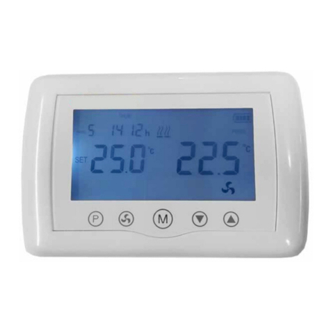
1. Bymeansofoption954=Individualon/offcontrol(0%or100%functioning)
2. Bymeansofoption952=weeklyprogrammingdigitalchronothermostat(GA11)usedforremotecontrolof
severalunits(consultoption952instructionformoredetails)
Example
3. Bymeansof0‐10Vpowersignal(tobeperformedbycustomer)
Example
This manual suits for next models
4
Table of contents
Other Reznor Heater manuals

Reznor
Reznor RHC 4000 RJL Series User guide

Reznor
Reznor VR Series Owner's manual

Reznor
Reznor BE User manual

Reznor
Reznor UEZ User manual

Reznor
Reznor UBZ User manual

Reznor
Reznor UBX Owner's manual

Reznor
Reznor UDX Installation and operating instructions

Reznor
Reznor RHC21 4000 Guide

Reznor
Reznor Euro-T 2530D User manual

Reznor
Reznor CAUA User manual

Reznor
Reznor CAUA User manual

Reznor
Reznor RIH Series Owner's manual

Reznor
Reznor OUH Series User manual

Reznor
Reznor CAUA User manual

Reznor
Reznor CAUA User manual

Reznor
Reznor ML 1511 Guide

Reznor
Reznor EGW Series Guide

Reznor
Reznor VPS User manual

Reznor
Reznor EBHB User manual

Reznor
Reznor LDAP User manual