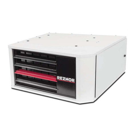
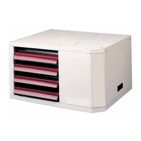
Reznor PHOTON-P User manual

D301362 Issue 0 October 2021
INSTALLATION INSTRUCTION ADDENDUM / L'ADD D'INSTRUCTION D'INSTALLATION
INSTALLATIE INSTRUCTIE ADDENDUM / ZUSATZ ZUR MONTAGEANLEITUNG
ANEXO DE INSTRUCCIONES DE INSTALACIÓN / UZUPEŁNIENIE DO INSTRUKCJI MONTAŻU
For/pour/voor/für/para/dla
PROPANE FIRED / FEU DE PROPANE
PROPANE GEVUURD / PROPANBETRIEB
COMBUSTIBLE DE PROPANO / OPALANE PROPANEM
PHOTON-P
Unit Heaters / Aeortherme a Gaz /
Gasgestookte Luchtver / Gas-Warmlufterzeuger
Calentadores Unitarios / Grzejniki Jednostkowe

D301362 Issue 0 October 2021
Page 2 of 40
EN
This addendum has been produced for the propane fired
(Photon-P) version of the Photon Unit Heater. This
addendum highlights the differences between the
Photon-P and the standard Photon Unit Heater.
This addendum must be read in conjunction with the
Photon Unit Heater Installation Manual. It does not
supersede or replace the Photon Unit Heater Installation
Manual in any way. Particular attention must be paid to
the “Important Notice to Installers” and Health and
Safety” Sections of the of the installation manual.
FR
Cet addenda a été produit pour la version au propane
(Photon-P) de l'aérotherme Photon. Cet addenda souligne
les différences entre le Photon-P et l'aérotherme Photon
standard.
Cet addenda doit être lu en conjonction avec le manuel
d'installation de l'aérotherme Photon. Il ne remplace en
aucun cas le manuel d'installation de l'aérotherme
Photon. Une attention particulière doit être portée aux
sections "Avis important aux installateurs" et "Santé et
sécurité" du manuel d'installation.
NL Dit addendum is gemaakt voor de propaan gestookte
(Photon-P) versie van de Photon Unit Heater. Dit
addendum benadrukt de verschillen tussen de Photon-P
en de standaard Photon Unit Heater.
Dit addendum moet worden gelezen in combinatie met
de Photon Unit Heater Installatie handleiding. Het
vervangt of vervangt de Photon Unit Heater
Installatiehandleiding op geen enkele wijze. Bijzondere
aandacht moet worden besteed aan de hoofdstukken
"Belangrijke opmerking voor installateurs" en
"Gezondheid en veiligheid" van de installatiehandleiding.
DE Dieser Anhang wurde für die propanbefeuerte (Photon-
P) Version des Photon-Heizgeräts erstellt. Dieser Zusatz
hebt die Unterschiede zwischen dem Photon-P und dem
Standard-Photon-Heizgerät hervor.
Dieser Nachtrag muss in Verbindung mit dem
Installationshandbuch für das Photon-Heizgerät gelesen
werden. Er ersetzt in keiner Weise das Photon-Heizgerät-
Installationshandbuch. Beachten Sie insbesondere die
Abschnitte "Wichtige Hinweise für Installateure" und
"Gesundheit und Sicherheit" in der Installationsanleitung.
ES
Este apéndice se ha elaborado para la versión de propano
(Photon-P) del Photon Unit Heater. Este apéndice destaca
las diferencias entre el Photon-P y el Photon Unit Heater
estándar.
Este anexo debe leerse junto con el Manual de instalación
del Photon Unit Heater. No sustituye ni reemplaza en modo
alguno el Manual de instalación del calentador por unidad
Photon. Debe prestarse especial atención a las secciones
"Aviso importante para los instaladores" y "Salud y
seguridad" del manual de instalación.
PL
Niniejszy dodatek został opracowany dla wersji
propanowej (Photon-P) nagrzewnicy jednostkowej
Photon. Uzupełnienie to podkreśla różnice pomiędzy
Photon-P a standardową nagrzewnicą.
Niniejszy dodatek należy czytać w połączeniu z instrukcją
montażu nagrzewnicy. Nie zastępuje on w żaden sposób
instrukcji montażu. Szczególną uwagę należy zwrócić na
rozdziały "Ważne wskazówki dla instalatorów" oraz
"Bezpieczeństwo i higiena pracy" w instrukcji instalacji.

D301362 Issue 0 October 2021
Page 3 of 40
EN - ENGLISH
Technical Data Photon-P
This table replaces the technical data given on Page 8 of the Photon Installation Manual
Model PHOTON 25-P 35-P 45-P 55-P 65-P 70-P 100-P 120-P
Combustion Air and Flue Type 1B23 / B53 / C13 / C33 / C53
Heat Input (Hs) 2High Fire kW 32.40 38.80 51.60 58.00 70.00 86.00 119.00
144.00
Low Fire kW 17.82 19.20 26.83 29.16 42.57 47.30 59.50 73.80
Heat Input (Hi) 3High Fire kW 29.72 35.60 47.34 53.21 64.22 78.90 109.17 132.11
Low Fire kW 16.35 17.61 24.61 26.75 39.06 43.39 54.59 67.71
Heat Output High Fire kW 27.03 32.25 42.81 49.29 58.47 72.27 99.03 121.73
Low Fire kW 15.61 16.80 23.47 25.89 37.21 41.58 52.37 65.09
Gas Consumption (Hs) G31 4High Fire m3/h 1.22 1.46 1.94 2.18 2.63 3.23 4.48 5.42
Low Fire m3/h 0.67 0.72 1.01 1.10 1.60 1.78 2.24
2.78
Gas Consumption (Hs) G31 4High Fire l/h 4.52 5.42 7.20 8.10 9.77 12.00 16.61
20.10
Low Fire l/h 2.49 2.68 3.74 4.07 5.94 6.60 8.31 10.30
Gas Consumption (Hs) G31 4High Fire kg/h 2.32 2.77 3.69 4.14 5.00 6.15 8.50 10.29
Low Fire kg/h 1.27 1.37 1.92 2.08 3.04 3.38 4.25 5.27
Thermal Efficiency High Fire G31 (NCV) % 90.9 90.6 90.4 92.6 91.1 91.6 90.7 92.1
Gas Connection 5
BSP
½”
¾”
1”
Flue and Combustion Air Connection Collars (Indoor) 100 130
Maximum Flue Length m 9.0
Airflow m3/h 3035 4120 4562 5877 7125 8681 10350 17552
Motor Speed rpm 934 1328 1320 925 1335 1384 1332 1206
Temperature Rise at Maximum Airflow K 27 23 28 25 24 25 29 21
Horizontal Throw m 26 27 26 32 32 36 36 36
Noise Level 6dBA 49 51 51 51 56 59 60
62
Minimum Mounting Height 7m 2.5
Total Electricity Rating W 256 550 550 690 820 1000 1040 1900
Electrical Connection 230V / 1N / 50Hz
Protection Grade IP IP20
Net Weight kg 58 89 99 121 122 135 168
258
1. Gas appliance classification for approved venting methods are based on EN 1749:2020
2. Refers to gross calorific value of fuel
3. Refers to net calorific value of fuel
4. Propane gas: G31 Hs 95.65 MJ/m³ @ 15°C and 1013.25 mbar
5. There is a difference between the gas connection diameter and the diameter of the supply line. Always use the most adequate
diameter of the supply line to minimise the pressure drop through the gas pipes. If necessary, reduce the diameter of the supply line
at the inlet of the unit.
6. Sound pressure measured in dB(A) at 5m distance from the heater with A=160m2and Q=2
7. Minimum height from floor to bottom surface of the heater for safe use of the heater. Positioning of unit heaters for performance is
application dependant. Operation is affected by other air moving equipment in the room space, obstructions to the airflow,
draughts and/or close proximity to doors or windows etc. Care should be taken to avoid mounting the heaters higher than these
recommendations unless downturn nozzle options are used, as significant stratification may occur resulting in poor floor coverage
and higher energy losses through the roof structure. Isothermal conditions +/- 20°C ambient air temperature, discharge louvres zero
deflection, v=0.5m/s. The airflow will be influenced by the height of the building, mounting height of the unit, ambient temperature
and adjustment of the louvres.

D301362 Issue 0 October 2021
Page 4 of 40
Flue Gas Properties Photon-P
This table replaces the flue gas properties given on page 16 of the Photon Installation
Manual
Photon Model 25-P 35-P 45-P 55-P 65-P 70-P 100-P 120-P
Flue Gas Temperature High Fire ΔT °C 179.2 186.4 189.2 149.6 178.5 163.5 181.9 155.8
Flue Gas Temperature Low Fire ΔT °C 86.2 87.8 88.0 62.2 89.2 79.3 77.8 73.9
Mass Flow Rate Flue Gases High
Fire G31
kg/h 30.03 35.39 47.37 49.87 63.02 84.97 113.90 134.78
Flue Pressure at Maximum Flue
Resistance
Pa 4 12 25 5 4 2 11 40
Gas Connection - Propane
This information replaces the information given on page 17 of the Photon Installation
Manual regarding Gas Types
PHOTON-P unit heaters are designed to operate on propane gas (G31). Check that the gas supply, gas category and gas
inlet pressure is in accordance with the information given on the unit data plate. To let the unit function at maximal heat
output, the gas supply pipe MUST be correctly sized.
Gas Supply Details – Propane Gas
This table replaces the gas supply details given on page 18 of the Photon Installation
Manual
Country Gas
Category Gas Type
Nominal
Supply
Pressure
(mbar)
Minimum
Supply
Pressure
(mbar)
Maximum
Supply
Pressure
(mbar)
CZ, DK, HU, MT, NL, RO I3P (30) Propane Gas (G31) 30 25 35
BE, CH, CZ, ES, FR, GB, GR, HR, IE, IT, LU, PL,
PT, SI, SK, TR I3P (37) Propane Gas (G31) 37 25 45
AT, BE, CH, CZ, DE, ES, FR, GB, GR, HU, NL,
SK I3P (50) Propane Gas (G31) 50 42.5 57.5

D301362 Issue 0 October 2021
Page 5 of 40
Pre-Start Checks – Propane Gas
This information must be read in addition to the Pre-Start Checks given on page 21 of the
Photon Installation Manual
Ensure PHOTON-P unit heaters have a link cable fitted between internal wiring terminals GS / GS. Do not proceed if this
link is missing.
Gas Conversion - Propane
This information replaces the entire section given on page 23 of the Photon Installation
Manual regarding Gas Conversion
PHOTON-P unit heaters are designed to operate on propane gas type G31. To modify for use on an alternative listed gas
type, contact the appliance manufacturer for further information.
Propane wiring link

D301362 Issue 0 October 2021
Page 6 of 40
Nominal Combustion Values with Service Door Closed – Photon-P
This table replaces the Nominal Combustion Values table given on page 25 of the Photon
Installation Manual
Model 25-P 35-P 45-P 55-P 65-P 70-P 100-P 120-P
CO2 at High Fire (Throttle) G31 % 9.80 9.90 9.80 9.90 9.90 9.70 9.70 9.80
CO ppm < 50 ppm
Throttle turns from closed 3.0 out
3.25
out
4.5 out
4.75
out
5.25
out
4.75
out
24.0 in 24.5 in
CO2 at Low Fire (Offset) G31 % 9.00 9.00 9.00 9.00 9.00 9.00 9.00 9.00
CO ppm < 50 ppm
Low Fire Offset Pressure (G31) Pa 35 47 70 76 99 104 6 9
Flue Gas Temperature High Fire
ΔT
°C 179.2 186.4 189.2 149.6 178.5 163.5 181.9 155.8
Flue Gas Temperature Low Fire
ΔT
°C 86.2 87.8 88.0 62.2 89.2 79.3 77.8 73.9
Flue Pressure at Maximum Flue
Resistance
Pa 70 10 19 18 11 14 23 6
Thermal Efficiency High Fire NCV % 90.9 90.6 90.4 92.6 91.1 91.6 90.7 92.1
Thermal Efficiency Low Fire NCV % 95.5 95.4 95.4 96.8 95.3 95.8 95.9 96.1
Ignition Controller Program Key Ω 3,300 4,700 6,800 10,000 15,000 22,000 33,000 56,000
Gas Valve Orifice Size mm 4.4 5.2 6.0 6.8 6.8 6.8 7.4 7.4
Maintenance Schedule - Propane
This information must be read in addition to the information given on page 33 of the
Photon Installation Manual under the heading Maintenance Schedule
PHOTON-P models have an orifice fitted between the gas valve and venturi. This orifice should be retained and refitted
when replacing the gas valve or venturi to ensure correct appliance operation.
Propane gas valve orifice

D301362 Issue 0 October 2021
Page 7 of 40
Cleaning and Replacement of Burner Probes - Propane
This information must be read in addition to the information given on page 38 of the
Photon Installation Manual under the heading Cleaning and Replacement of Burner Probes
PHOTON-P models 100 and 120 have a special spark probe assembly. Dimensions for checking are as follows: -
Length of probe = 79.4mm long probe, 43.2mm short probe.
4.1mm +/- 0.5mm gap between probes.
Angle of probes 22.3°
Spare Parts - Propane
This information must be read in addition to the information given on page 45 of the
Photon Installation Manual under the heading Spare Parts
Description
Part Number
Application
4.4mm gas valve orifice
1037652
25-P
5.2mm gas valve orifice
1037653
35-P
6.0mm gas valve orifice
03-25800-02
45-P
6.8mm gas valve orifice
1037654
55-70-P
7.4mm gas valve orifice & O-ring
1037655
100-120-P
Propane Gas Selection (GS) Jumper
1030922
All

D301362 Issue 0 October 2021
Page 8 of 40
ErP Table – G31 Propane
This information replaces the information given on pages 47, 48 and 49 of the Photon
Installation Manual under the heading ErP Tables
120-P
Capacity
121.7
65.1
Electrical Power consumption
0.395
0.120
0.001
Useful efficiency
84.5
88.2
Other
items
0.0
0.0
48
95.9
82.1
92.1
100-P
99.0
52.4
0.274
0.098
0.001
83.2
88.0
0.0
0.0
69
94.3
80.4
90.7
70-P
72.3
416
0.178
0.048
0.001
84.0
87.9
0.0
0.0
67
94.8
80.6
91.6
65-P
58.5
37.2
0.120
0.048
0.001
83.5
87.4
0.0
0.0
53
94.4
79.3
91.1
55-P
49.3
25.9
0.065
0.013
0.001
85.0
88.8
0.0
0.0
66
95.1
82.2
92.6
45-P
42.8
23.5
0.067
0.021
0.001
83.0
87.5
0.0
0.0
47
94.3
79.9
90.4
35-P
32.3
16.8
0.079
0.039
0.001
83.1
87.5
0.0
0.0
65
95.5
81.0
90.6
25-P
27.0
15.6
0.047
0.028
0.001
83.4
87.6
0.0
0.0
68
94.4
79.8
90.9
Photon
Units
kW
kW
kW
kW
kW
%
%
%
kW
Mg/kWh
%
%
%
Symbol
Pnom
Pmin
elmax
elmin
elsb
η th, nom
η th, min
Fenv
Pign
NOx
η s, flow
ηs
η
Model
Item
Rated heating capacity
Minimum capacity
At rated heating capacity
At minimal capacity
In standby mode
Useful efficiency at rated heating capacity
Useful efficiency at minimum capacity
Envelope loss factor
Flame consumption
Emissions of nitrogen
oxides (input energy GCV
Emission efficiency
ErP seasonal space heating energy
efficiency
Thermal efficiency at rated heating capacity NCV

D301362 Issue 0 October 2021
Page 9 of 40
FR - FRANÇAIS
Données Techniques Photon-P
Ce tableau remplace les données techniques figurant à la page 8 du manuel d'installation du Photon
Modèle PHOTON 25-P 35-P 45-P 55-P 65-P 70-P 100-P 120-P
Air de combustion et type d’evacuation1B23 / B53 / C13 / C33 / C53
Débit calorifique (Hs) 2Max PCS kW 32.40 38.80 51.60 58.00 70.00 86.00 119.00 144.00
Min PCS kW 17.82 19.20 26.83 29.16 42.57 47.30 59.50 73.80
Débit calorifique (Hi) 3Max PCS kW 29.72 35.60 47.34 53.21 64.22 78.90 109.17 132.11
Min PCS kW 16.35 17.61 24.61 26.75 39.06 43.39 54.59 67.71
Puissance nominale Max PCS kW 27.03 32.25 42.81 49.29 58.47 72.27 99.03 121.73
Min PCS kW 15.61 16.80 23.47 25.89 37.21 41.58 52.37 65.09
Consommation de gaz à débit
calorifique (Hs) G31 4
Max PCS m3/h 1.22 1.46 1.94 2.18 2.63 3.23 4.48 5.42
Min PCS m3/h 0.67 0.72 1.01 1.10 1.60 1.78 2.24 2.78
Consommation de gaz à débit
calorifique (Hs) G31 4
Max PCS l/h 4.52 5.42 7.20 8.10 9.77 12.00 16.61 20.10
Min PCS l/h 2.49 2.68 3.74 4.07 5.94 6.60 8.31 10.30
Consommation de gaz à débit
calorifique (Hs) G31 4
Max PCS kg/h 2.32 2.77 3.69 4.14 5.00 6.15 8.50 10.29
Min PCS kg/h 1.27 1.37 1.92 2.08 3.04 3.38 4.25 5.27
Rendement thermique à pleine charge G31
(NCV) % 90.9 90.6 90.4 92.6 91.1 91.6 90.7 92.1
Raccordement du gaz 5BSP ½” ¾”
1”
Évacuation et bagues de raccordement d'air de combustion
(intérieures)
100 130
Longueur d'évacuation maximale
m 9.0
Débit d'air
m3/h 3035 4120 4562 5877 7125 8681 10350 17552
Vitesse du moteur
rpm 934 1328 1320 925 1335 1384 1332 1206
Augmentation de température au débit d'air
maximum
K 27 23 28 25 24 25 29 21
Jet d’air horizontale m 26 27 26 32 32 36 36 36
Niveau sonore
6dBA 49 51 51 51 56 59 60 62
Hauteur de montage minimale
7m 2.5
Puissance électrique totale
W 256 550 550 690 820 1000 1040 1900
Connexion électrique
230V / 1N / 50Hz
Protection IP IP20
Poids net kg 58 89 99 121 122 135 168 258
1.
Les classifications d'appareils au gaz pour les méthodes d'aération approuvées sont basées sur la norme EN 1749:2020
2.
Se rapporte à la valeur calorifique brute du combustible
3.
Se rapporte à la valeur calorifique nette du combustible
4. Gaz propane: G31 Hs 95.65 MJ/m³ @ 15°C et 1013.25 mbar
5.
Il existe une différence entre le diamètre de raccordement au gaz et le diamètre de la ligne d'alimentation. Utilisez toujours le diamètre le plus adéquat de la
ligne d'alimentation pour minimiser la chute de pression dans les tuyaux de gaz. Si nécessaire, réduisez le diamètre de la ligne d'alimentation à l'entrée de
l'appareil
6.
Pression acoustique mesurée en dB(A) : à 5 m de distance de l'appareil avec
A=160m2and Q=2
7.
Hauteur minimale du sol à la surface inférieure de l'appareil pour une utilisation de ce dernier en toute sécurité. Le positionnement des aérothermes pour un
rendement approprié dépend de l'application. Le fonctionnement est influencé par d'autres matériels à déplacement d'air dans l'espace, les obstacles à
l'écoulement de l'air, les tirages et/ou la proximité des portes ou des fenêtres, etc. On veillera à éviter de monter les appareils à une hauteur supérieure à ces
recommandations, sauf si des buses descendantes en option sont utilisées, étant donné qu'une stratification importante peut se produire qui entraîne une
couverture défectueuse du sol et des pertes d'énergie supérieures à travers la structure de la toiture. Des conditions isothermes à +/-20°C de température de
l'air ambiant, des volets de refoulement à déflexion zéro, v = 0,5m/s. Le débit d'air sera influencé par la hauteur du bâtiment, la hauteur de montage de
l'appareil, la température ambiante et le réglage des volets
.

D301362 Issue 0 October 2021
Page 10 of 40
Propriétés du gaz d’evacuation Photon-P
Ce tableau remplace les propriétés des gaz de combustion indiquées à la page 16 du manuel
d'installation du Photon
25-P 35-P 45-P 55-P 65-P 70-P 100-P 120-P
Température du gaz d'évacuation
feu vif ΔT °C 179.2 186.4 189.2 149.6 178.5 163.5 181.9 155.8
Température du gaz d'évacuation
feu doux ΔT °C 86.2 87.8 88.0 62.2 89.2 79.3 77.8 73.9
Débit massique des gaz
d'évacuation feu vif G31 kg/h 30.03 35.39 47.37 49.87 63.02 84.97 113.90 134.78
Pression d'évacuation à la
résistance d'évacuation maximale Pa 4 12 25 5 4 2 11 40
Raccordement au gaz - Propane
Ces informations remplacent les informations données à la page 17 du manuel d'installation
du Photon concernant les types de gaz.
Les aérothermes PHOTON-P sont conçus pour fonctionner au gaz propane (G31). Vérifiez que l'alimentation en gaz, la
catégorie de gaz et la pression d'entrée du gaz sont conformes aux informations indiquées sur la plaque signalétique de
l'appareil. Pour permettre à l'appareil de fonctionner avec une puissance thermique maximale, le tuyau d'alimentation en
gaz DOIT être correctement dimensionné.
Détails de l'alimentation en gaz – Gaz Propane
Ce tableau remplace les détails de l'alimentation en gaz donnés à la page 18 du manuel
d'installation du Photon.
Pays Catégorie
de gaz Type de gaz
Pression
d'alimentation
nominale
(mbar)
Pression
d'alimentation
minimale
(mbar)
Pression
d'alimentation
maximale
(mbar)
CZ, DK, HU, MT, NL, RO I3P (30) Gaz Propane (G31) 30 25 35
BE, CH, CZ, ES, FR, GB, GR, HR, IE,
IT, LU, PL, PT, SI, SK, TR I3P (37) Gaz Propane (G31) 37 25 45
AT, BE, CH, CZ, DE, ES, FR, GB, GR,
HU, NL, SK I3P (50) Gaz Propane (G31) 50 42.5 57.5

D301362 Issue 0 October 2021
Page 11 of 40
Contrôles avant le démarrage - Gaz propane
Ces informations doivent être lues en plus des vérifications avant démarrage
indiquées à la page 21 du manuel d'installation du Photon.
Assurez-vous que les aérothermes PHOTON-P sont équipés d'un câble de liaison entre les bornes de câblage interne GS /
GS. Ne pas poursuivre si ce lien est absent.
Conversion du gaz – Propane
Ces informations remplacent toute la section de la page 23 du manuel d'installation du
Photon concernant la conversion au gaz.
Les aérothermes PHOTON-P sont conçus pour fonctionner avec du gaz propane de type G31. Pour modifier l'appareil afin
de l'utiliser avec un autre type de gaz, contactez le fabricant de l'appareil pour plus d'informations.
Lien de câblage
pour le propane

D301362 Issue 0 October 2021
Page 12 of 40
Valeurs de combustion nominales avec porte de service fermée – Photon-P
This table replaces the Nominal Combustion Values table given on page 25 of the Photon
Installation Manual
Model 25-P 35-P 45-P 55-P 65-P 70-P 100-P 120-P
CO2 a feu vif (volet du gaz) G31 % 9.80 9.90 9.80 9.90 9.90 9.70 9.70 9.80
CO ppm < 50 ppm
Rotation du volet de gaz à partir
de la position fermée 3.0 out 3.25
sortie
4.5
sortie
4.75
sortie
5.25
sortie
4.75
sortie
24.0
entrėe
24.5
entrėe
CO2 à feu doux (dérivation) G31 % 9.00 9.00 9.00 9.00 9.00 9.00 9.00 9.00
CO ppm < 50 ppm
Pression de dérivation feu doux
G31 Pa 35 47 70 76 99 104 6 9
Température du gaz d'évacuation
feu vif ΔT °C 179.2 186.4 189.2 149.6 178.5 163.5 181.9 155.8
Température du gaz d'évacuation
feu doux ΔT
°C 86.2 87.8 88.0 62.2 89.2 79.3 77.8 73.9
Pression d'évacuation à la
résistance d'évacuation maximal Pa 70 10 19 18 11 14 23 6
Efficacité thermique feu vif NCV % 90.9 90.6 90.4 92.6 91.1 91.6 90.7 92.1
Efficacité thermique feu doux
NCV % 95.5 95.4 95.4 96.8 95.3 95.8 95.9 96.1
Clé du programme de commande
d'allumage Ω 3,300 4,700 6,800 10,000 15,000 22,000 33,000 56,000
Taille de l'orifice de la vanne de
gaz
mm 4.4 5.2 6.0 6.8 6.8 6.8 7.4 7.4

D301362 Issue 0 October 2021
Page 13 of 40
Programme de maintenance - Propane
Ces informations doivent être lues en complément des informations données à la page 33
du manuel d'installation du Photon, sous la rubrique programme de maintenance.
Les modèles PHOTON-P sont équipés d'un orifice monté entre la vanne de gaz et le venturi. Cet orifice doit être conservé
et remis en place lors du remplacement de la vanne de gaz ou du venturi pour assurer le bon fonctionnement de
l'appareil.
Orifice de la vanne de gaz propane
Nettoyage et remplacement des sondes de brûleur - Propane
Ces informations doivent être lues en complément des informations données à la page 39
du manuel d'installation du Photon sous le titre Nettoyage et remplacement des sondes de
brûleur.
Les modèles PHOTON-P 100 et 120 ont un assemblage spécial de sonde d'étincelle. Les dimensions à vérifier sont les
suivantes : -
Longueur de la sonde = 79,4mm pour la sonde longue, 43,2mm pour la sonde courte.
Espace de 4,1 mm +/- 0,5 mm entre les sondes.
Angle des sondes 22,3°.
Pièces de rechange - Propane
Ces informations doivent être lues en complément des informations données à la page 45
du manuel d'installation du Photon sous la rubrique Pièces de rechange.
Description
Référence
Application
4.4mm orifice de la valve de gaz
1037652
25-P
5.2mm orifice de la valve de gaz
1037653
35-P
6.0mm orifice de la valve de gaz
03-25800-02
45-P
6.8mm orifice de la valve de gaz
1037654
55-70-P
7.4mm orifice et joint torique de la
valve de gaz
1037655
100-120-P
Cavalier de sélection du gaz propane
(GS)
1030922
Tous

D301362 Issue 0 October 2021
Page 14 of 40
Tableau ErP – G31 Propane
Ces informations remplacent celles qui figurent aux pages 47, 48 et 49 du manuel
d'installation du Photon, sous la rubrique Tableaux ErP.
120-P
Capacit
é
121.7
65.1
Consommation de courant électrique
0.395
0.120
0.001
Efficacité utile
84.5
88.2
Autres éléments
0.0
0.0
48
95.9
82.1
92.1
100-P
99.0
52.4
0.274
0.098
0.001
83.2
88.0
0.0
0.0
69
94.3
80.4
90.7
70-P
72.3
416
0.178
0.048
0.001
84.0
87.9
0.0
0.0
67
94.8
80.6
91.6
65-P
58.5
37.2
0.120
0.048
0.001
83.5
87.4
0.0
0.0
53
94.4
79.3
91.1
55-P
49.3
25.9
0.065
0.013
0.001
85.0
88.8
0.0
0.0
66
95.1
82.2
92.6
45-P
42.8
23.5
0.067
0.021
0.001
83.0
87.5
0.0
0.0
47
94.3
79.9
90.4
35-P
32.3
16.8
0.079
0.039
0.001
83.1
87.5
0.0
0.0
65
95.5
81.0
90.6
25-P
27.0
15.6
0.047
0.028
0.001
83.4
87.6
0.0
0.0
68
94.4
79.8
90.9
Photon
Units
kW
kW
kW
kW
kW
%
%
%
kW
Mg/kWh
%
%
%
Symbol
Pnom
Pmin
elmax
elmin
elsb
η th, nom
η th, min
Fenv
Pign
NOx
η s, flow
ηs
η
Modėle
Élėlemnt
Capacité de chauffage nominale
Capacité m
inimale
A la capacité de chauffage nominale
A la capacité minimale
En mode standby
Efficacité utile à la capacité de chauffage nominale
Efficacité utile à la capacité minimale
Facteur de perte
d'enveloppe
Consommation de flamme
Émissions d'oxydes d'azote (énergie d'entrée)
GCV
Efficacité des émissions
Efficacité énergétique saisonnière du chauffage des locaux
ErP
Rendement thermique à la puissance calorifique nominale
NCV

D301362 Issue 0 October 2021
Page 15 of 40
NL - NEDERLAND
Technische Gegevens Photon-P
Deze tabel vervangt de technische gegevens op pagina 8 van de Photon
installatiehandleiding
Model PHOTON 25-P 35-P 45-P 55-P 65-P 70-P 100-P
120-P
Verbrandingslucht en rookgaskanaal
t
ype 1B23 / B53 / C13 / C33 / C53
Warmte-input (Hs) 2Hoog vuur kW 32.40 38.80 51.60 58.00 70.00 86.00 119.00 144.00
Laag vuur kW 17.82 19.20 26.83 29.16 42.57 47.30 59.50 73.80
Warmte-input (Hi) 3Hoog vuur kW 29.72 35.60 47.34 53.21 64.22 78.90 109.17 132.11
Laag vuur kW 16.35 17.61 24.61 26.75 39.06 43.39 54.59 67.71
Warmteafgifte Hoog vuur kW 27.03 32.25 42.81 49.29 58.47 72.27 99.03 121.73
Laag vuur kW 15.61 16.80 23.47 25.89 37.21 41.58 52.37
65.09
Gasverbruik (Hs) G31 4Hoog vuur m3/h 1.22 1.46 1.94 2.18 2.63 3.23 4.48 5.42
Laag vuur m3/h 0.67 0.72 1.01 1.10 1.60 1.78 2.24 2.78
Gasverbruik (Hs) G31 4Hoog vuur l/h 4.52 5.42 7.20 8.10 9.77 12.00 16.61 20.10
Laag vuur l/h 2.49 2.68 3.74 4.07 5.94 6.60 8.31 10.30
Gasverbruik (Hs) G31 4Hoog vuur kg/h 2.32 2.77 3.69 4.14 5.00 6.15 8.50
10.29
Laag vuur kg/h 1.27 1.37 1.92 2.08 3.04 3.38 4.25 5.27
Thermisch rendement maximum
vermogen G31 (NCV) % 90.9 90.6 90.4 92.6 91.1 91.6 90.7 92.1
Gasaansluiting
5
BSP
½”
¾”
1”
Halzen rookgas en verbrandingslucht (binnen)
100 130
Maximale lengte rookkanaal m 9.0
Luchtstroom m3/h 3035 4120 4562 5877 7125 8681 10350 17552
Motorsnelheid rpm 934 1328 1320 925 1335 1384 1332 1206
Temperatuurstijging bij maximale
luchtstroom
K 27 23 28 25 24 25 29 21
Horizontale worp m 26 27 26 32 32 36 36 36
Geludsniveau 6dBA 49 51 51 51 56 59 60 62
Minimal montagehoogte 7m 2.5
Totaal elektrisch vermogen W 256 550 550 690 820 1000 1040 1900
Elektrisch aansluiting 230V / 1N / 50Hz
Beschermingsgraad IP IP20
Netto gewicht kg 58 89 99 121 122 135 168 258
1.
De classificaties van gastoestellen voor goedgekeurde ontluchtingsmethoden zijn gebaseerd op
EN 1749:2020
2.
Verwijst naar de calorische bovenwaarde van de brandstof
3.
Verwijst naar de calorische onderwaarde van de brandstof
4. Propaangas gas: G31 Hs 95.65 MJ/m³ @ 15°C and 1013.25 mbar
5.
Er is een verschil tussen de diameter van de gasaansluiting en de die van de toevoerleiding. Gebruik altijd de meest geschikte diameter van de toevoerleiding
om de drukval door de gasleidingen zo klein mogelijk te houden. Verklein, indien nodig, de diameter van de toevoerleiding aan de inlaat van het toestel
6.
Geluidsdruk gemeten in dB(A) : op 5m afstand van het verwarmingstoestel met
A=160m2and Q=2
7.
Minimumhoogte van de vloer tot de onderkant van het verwarmingstoestel voor een veilig gebruik van het verwarmingstoestel. De plaatsing van
luchtverhitters voor een goede werking is afhankelijk van de toepassing. De werking wordt beïnvloed door andere luchtverplaatsende apparatuur in de
ruimte, belemmeringen van de luchtstroom, tocht en/of de nabijheid van deuren of ramen, enz. De verwarmingstoestellen mogen niet hoger dan deze
aanbevelingen worden gemonteerd, tenzij er gebruik wordt gemaakt van nozzle-opties, omdat er dan een aanzienlijke stratificatie kan optreden die
resulteert in een slechte vloerdekking en hogere energieverliezen via de dakconstructie. Isothermische omstandigheden +/-20°C omgevingstemperatuur,
uitblaasroosters geen afbuiging, v = 0,5m/s. De luchtverplaatsing wordt beïnvloed door de hoogte van het gebouw, de montagehoogte van het toestel, de
omgevingstemperatuur en de afstelling van de roosters
.

D301362 Issue 0 October 2021
Page 16 of 40
Rookgaseigenschappen Photon-P
Deze tabel vervangt de rookgaseigenschappen op pagina 16 van de Photon
installatiehandleiding
Photon Model 25-P 35-P 45-P 55-P 65-P 70-P 100-P 120-P
Rookgastemperatuur hoge temperatuur ΔT °C 179.2 186.4 189.2 149.6 178.5 163.5 181.9 155.8
Rookgastemperatuur lage temperatuur ΔT °C 86.2 87.8 88.0 62.2 89.2 79.3 77.8 73.9
Massadebiet rookgassen hoge temperatuur
G31 kg/h 30.03 35.39 47.37 49.87 63.02 84.97 113.90 134.78
Rookgasdruk bij maximale rookgasweerstand Pa 4 12 25 5 4 2 11 40
Gasaansluiting - Propaan
Deze informatie vervangt de informatie op pagina 17 van de Photon installatiehandleiding
met betrekking tot gassoorten
De PHOTON-P luchtverhitters zijn ontworpen om te werken op propaangas (G31). Controleer of de gastoevoer, de
gascategorie en de gasinlaatdruk in overeenstemming zijn met de gegevens op het gegevensplaatje van het toestel. Om
het toestel maximaal te laten werken, MOET de gastoevoerleiding de juiste dimensionering hebben.
Details gasvoorziening - Propaangas
Deze tabel vervangt de gegevens over de gastoevoer op pagina 18 van de Photon
installatiehandleiding
Land Gas-
Categorie Gassoort
Nominale
toevoerdruk
(mbar)
Minimale
toevoerdruk
(mbar)
Maximale
toevoerdruk
(mbar)
CZ, DK, HU, MT, NL, RO I3P (30) Propaangas (G31) 30 25 35
BE, CH, CZ, ES, FR, GB, GR, HR, IE, IT,
LU, PL, PT, SI, SK, TR I3P (37) Propaangas (G31) 37 25 45
AT, BE, CH, CZ, DE, ES, FR, GB, GR,
HU, NL, SK I3P (50) Propaangas (G31) 50 42.5 57.5

D301362 Issue 0 October 2021
Page 17 of 40
Controles vóór het starten - propaangas
Deze informatie moet worden gelezen als aanvulling op de controles vóór de
inbedrijfstelling op pagina 21 van de Photon installatiehandleiding
Zorg ervoor dat de PHOTON-P verwarmingssystemen een verbindingskabel hebben tussen de interne bedradingsklemmen
GS / GS. Ga niet verder als deze verbinding ontbreekt.
Gasconversie – Propaan
Deze informatie vervangt het volledige hoofdstuk op pagina 23 van de Photon
installatiehandleiding betreffende de gasconversie
PHOTON-P luchtverhitters zijn ontworpen om te werken op propaangas type G31. Neem contact op met de fabrikant van
het toestel voor meer informatie over het wijzigen van de toestellen voor gebruik op een ander gastype..
Propaan bedrading
link

D301362 Issue 0 October 2021
Page 18 of 40
Nominale verbrandingswaarden met gesloten bedrijfsdeur – Photon-P
Deze tabel vervangt de tabel met nominale verbrandingswaarden op pagina 25 van de
Photon installatiehandleiding
Model 25-P 35-P 45-P 55-P 65-P 70-P 100-P 120-P
CO2 bij hoge temperatuur
(gashendel) G31 % 9.80 9.90 9.80 9.90 9.90 9.70 9.70 9.80
CO ppm < 50 ppm
Gashendel draait vanaf gesloten 3.0 uit 3.25 uit 4.5 uit 4.75 uit 5.25 uit 4.75 uit 24.0 in 24.5 in
CO2 bij lage temperatuur (Offset)
G31 % 9.00 9.00 9.00 9.00 9.00 9.00 9.00 9.00
CO ppm < 50 ppm
Lage brandcompressiedruk (G31) Pa 35 47 70 76 99 104 6 9
Rookgastemperatuur hoge
temperatuur ΔT °C 179.2 186.4 189.2 149.6 178.5 163.5 181.9 155.8
Rookgastemperatuur lage
temperatuur ΔT °C 86.2 87.8 88.0 62.2 89.2 79.3 77.8 73.9
Rookgasdruk bij maximale
rookgasweerstand Pa 70 10 19 18 11 14 23 6
Thermisch rendement hoge
temperatuur NCV % 90.9 90.6 90.4 92.6 91.1 91.6 90.7 92.1
Thermisch rendement lage
temperatuur NCV % 95.5 95.4 95.4 96.8 95.3 95.8 95.9 96.1
Ontstekingsregelaar
programmasleutel Ω 3,300 4,700 6,800 10,000 15,000 22,000 33,000 56,000
Gasafsluiter Openingsmaat mm 4.4 5.2 6.0 6.8 6.8 6.8 7.4 7.4

D301362 Issue 0 October 2021
Page 19 of 40
Onderhoudsschema - Propaan
Deze informatie moet worden gelezen in aanvulling op de informatie op pagina 33 van de
Photon installatiehandleiding onder de rubriek Onderhoudsschema
De PHOTON-P modellen hebben een opening tussen de gasklep en de venturi. Deze opening moet worden behouden en
opnieuw worden gemonteerd wanneer de gasklep of venturi wordt vervangen om een correcte werking van het toestel te
garanderen.
Propaan gasklep opening
Reinigen en vervangen van brandersondes – Propaan
Deze informatie moet worden gelezen in aanvulling op de informatie op pagina 38 van de
Photon installatiehandleiding onder de rubriek Reiniging en vervanging van brandersondes
De PHOTON-P modellen 100 en 120 hebben een speciale vonksonde. De afmetingen voor de controle zijn als volgt: -
Lengte van de sonde = 79.4mm lange sonde, 43.2mm korte sonde.
4.1mm +/- 0.5mm tussenruimte tussen de sondes.
Hoek van sondes 22.3°
Reserveonderdelen – Propaan
Deze informatie moet worden gelezen in aanvulling op de informatie op pagina 45 van de
Photon installatiehandleiding onder de rubriek Reserveonderdelen
Beschrijving
Onderdee nommer
Toepassing
4.4mm Gasklep opening
1037652
25-P
5.2mm Gasklep opening
1037653
35-P
6.0mm Gasklep opening
03-25800-02
45-P
6.8mm Gasklep opening
1037654
55-70-P
7.4mm Gasklep opening & O-ring
1037655
100-120-P
Propaan Gas Selectie (GS) Jumper
1030922
Alle

D301362 Issue 0 October 2021
Page 20 of 40
ErP Tabel – G31 Propaan
Deze informatie vervangt de informatie op de bladzijden 47, 48 en 49 van de Photon
installatiehandleiding onder de rubriek ErP-tabellen
120-P
Capacit
121.7
65.1
Elektrisch Vermogensverbruik
0.395
0.120
0.001
Nuttig rendement
84.5
88.2
Andere items
0.0
0.0
48
95.9
82.1
92.1
100-P
99.0
52.4
0.274
0.098
0.001
83.2
88.0
0.0
0.0
69
94.3
80.4
90.7
70-P
72.3
416
0.178
0.048
0.001
84.0
87.9
0.0
0.0
67
94.8
80.6
91.6
65-P
58.5
37.2
0.120
0.048
0.001
83.5
87.4
0.0
0.0
53
94.4
79.3
91.1
55-P
49.3
25.9
0.065
0.013
0.001
85.0
88.8
0.0
0.0
66
95.1
82.2
92.6
45-P
42.8
23.5
0.067
0.021
0.001
83.0
87.5
0.0
0.0
47
94.3
79.9
90.4
35-P
32.3
16.8
0.079
0.039
0.001
83.1
87.5
0.0
0.0
65
95.5
81.0
90.6
25-P
27.0
15.6
0.047
0.028
0.001
83.4
87.6
0.0
0.0
68
94.4
79.8
90.9
Photon
Units
kW
kW
kW
kW
kW
%
%
%
kW
Mg/kWh
%
%
%
Symbol
Pnom
Pmin
elmax
elmin
elsb
η th, nom
η th, min
Fenv
Pign
NOx
η s, flow
ηs
η
Model
Item
Nominaal verwarmingsvermogen
Minimaal vermogen
Bij nominaal verwarmingsvermogen
Bij minima
al capaciteit
In stand
-by
Nuttig rendement bij nominaal
verwarmingsvermogen
Nuttige efficiëntie bij minimale capaciteit
Verliesfactor omhulling
Vlamverbruik
Stikstofoxide
-
emissies (toevoer energie
Emissierendement
ErP seizoensg ebonden energierendement
ruimteverwarming
Thermisch rendement bij nominaal
verwarmingsvermogen (NCV)
This manual suits for next models
8
Table of contents
Languages:
Other Reznor Heater manuals

Reznor
Reznor CAUA User manual

Reznor
Reznor AirBloc AC Series User manual

Reznor
Reznor FT30-CV Installation and user guide

Reznor
Reznor FT Series User manual

Reznor
Reznor ULSA 035(EC) User manual

Reznor
Reznor UBX Owner's manual

Reznor
Reznor EBHB Guide

Reznor
Reznor RHC 8000(m) RJL Instruction Manual

Reznor
Reznor CAUA User manual

Reznor
Reznor BE User manual