RHINO FSD User manual

Local Air Conditioner
Thank you for selecting this air-conditioner. Please keep this User’s Manual for future reference.
Read the User’s Manual carefully before operating this unit.
IMPORTANT SAFEGUARDS
• This air-conditioner is suitable for indoor use only.
• Rated operating range: this unit shall be connected to 220-240V / 50Hz power supply.
• Ensure this is used on a flat surface at least 50cm away from surrounding objects or walls.
• Once the air-conditioner is installed, ensure that the mains cable is in good condition and
inserted firmly into the power socket and always ensure that the power cord is arranged in
such a way to avoid tripping or the plug from being pulled out.
• Do not insert any object into the air inlet/outlet of the air-conditioner. Be sure to keep the
air inlet/outlet of the air-conditioner unblocked.
• Where there is the need to install a drain pipe, ensure that the connection of the drain
pipe is secure without kinks.
• When adjusting the horizontal/vertical louver at the air outlet, turn it slightly by hand to
avoid damage of the Louvre.
• Keep the unit in an upright position when moving or repositioning.
• Keep this unit away from petrol, flammable gases, or other heat sources.
• Do not dismantle, inspect or modify the unit without authorisation as this may impair the
unit, cause personal injuries or property damage; to avoid dangers, if the unit is faulty, be
sure to have it repaired by the manufacturer or a suitable qualified person.
• Do not operate this air-conditioner in a bathroom or other wet environments.
• Do not allow children to play with this machine. Closely supervise children when this unit
is in use.
• Do not turn off this unit by removing the plug.
• Do not place liquids on the unit.
• Do not use pest control aerosol or other flammable substances near the air-conditioner.
• Do not wipe or wash the air-conditioner with chemical solvents such as petroleum, aerosol or
alcohols, etc. Before cleaning the air-conditioner, be sure to turn off the power supply
and wipe it with a soft damp cloth; if the machine is very dirty, wipe it with a neutral cleaner.
RECOMMENDATION
Do not operate this unit if the ambient temperature is greater than 35˚C in the cooling mode or
lower than 5˚C in the heating mode.

FUNCTION DESCRIPTION
The mobile air-conditioner has the following functions available cooling, dry, air blowing and sleep
functions. The speed of the fan is adjustable between high fan speed and low fan speed, and
various functions such as (24h) timed ON/OFF setting.
FEATURES AND PARTS
1. Features
• Compact style design.
• The remote control features user-friendly memory design. A convenient storage pocket
is located on the right of the handle at the back of the unit.
• The rear of the unit includes a universal plug holder for convenient and safe storage of the
cable and plug.
• The position of the duct connector is high to allow for convenient assembly and smooth
air flow.
• Timed start/shutdown function, unique start/shutdown music.
• 3-minute delay compressor restart protection function.
• The snap-fit design of the exhaust hose allows for more convenient installation of the unit.
2. Parts:
1
2
3
4
5
6
7
8
9
10
11
12
13
14
15
16
17
18
19
20
21
22
23
24 25
26 27

Slide way of the
back shell
Snap joint of the
C shape buckle
of the back shell
Figure 1
Rotary hole
Rotation shaft of
the back shell
Figure 2
1. Control panel 14. Lower air duct
2. Horizontal louvre 15. Cable winding post
3. Vertical louvre 16. Drain cap
4. Air outlet frame 17. Evaporator filter mesh
5. Vertical Louvre connecting lever 18. Evaporator filter frame
6. Caster 19. Radiating fine mesh
7. Horizontal louvre connecting lever 20. Condenser filter mesh
8. Main vertical louver 21. Condenser filter frame
9. Front shell 22. Base plate
10. Handle position (right side: remote 23. Remote control
control storage area) 24. circular connector
11. Back shell 25. Heat exhaust hose
12. C shape buckle for the heat 26. Heat exhaust hose short connector
exhaust hose snap 27. Window sealing board assembly
13. Power cord
INSTALLATION ADJUSTMENT
1. Installation
WARNING: leave this mobile air-conditioner in an upright position for at least 2 hours before first
use. Ensure the air-conditioner in an upright position whilst moving . The air-conditioner should
be placed on a flat surface. Do not install or operate this air-conditioner in a bathroom or other
wet environments.
a) Installation of the exhaust clip to the rear of the unit. (figure 1)

Figure 3
Position of lower
air duct bottom step
Figure 4
Lower air duct
bottom joint
b) Rotate the exhaust clip counter-clockwise until the clip locks firmly into position as shown
below (as shown in Figure 2).
Do not rotate exhaust clip if not correctly aligned as this may damage the interlocking
components.
c) Installation of the exhaust hose assembly to the unit
Pull the end of the exhaust hose apart to allow easy access to the exhaust connector ;
Hold the exhaust clip clear of the duct opener. Align the exhaust connector to the opening on the
rear of the unit. Push the exhaust clip down to lock the hose in position(as shown in Figure 3).
The end of the exhaust hose must be secured on the bottom stop of the outlet. (as
shown in Figure 4).
Hold the unit with one hand and the heat exhaust hose short connector with other hand; or
get help and one person hold the unit and the other person pulls the heat exhaust hose gently.
Do not separate the heat exhaust hose assembly from the unit. Do not tilt the unit when
pulling apart the heat exhaust hose.
d) Installation of the window sealing board assembly
Half open the window and mount the window sealing board assembly onto the window,
either vertically or horizontally (as shown in Figure 5 and 6). Pull apart the parts of the window
sealing board assembly, adjust the distance of the window sealing board assembly pulled apart so
that the two ends of the assembly come into contact with the window frame, and fasten the parts
of the assembly with copper screws.
Note
Note
Note

Figure 5 Figure 6
Open the ducting hose and position the outlet
of the hose into a well ventilated area. The
exhaust hose may not be bent and shall be
free from significant kinks (greater than 45°).
The exhaust hose is 280mm-1000mm
long. Do not extend the hose or replace with
other different hoses as this may affect the
functions of the air-conditioner. The exhaust
must be kink and blockage free, note the
air-conditioner may overheat if the exhaust
is obstructed.
Figure 7
Figure 8
Figure 9
Note

POWER
MODE
FAN
TIMER
°F
Hr
C
°
Down button
Up button
Timer button ON/OFF button
Mode button
Fan button
Position of receiving head
of remote control
Fahrenheit
degree indicator
Double 8
display area
Celsius
degree
indicator
Regular time
indicator
CONTROL SETTING
One. Operation instructions of the control panel
1. Select the operation mode depending on the model and functions. The operation
mode is as follows:
FUNCTIONS SETTING
This portable air conditioner has three functions: cooling, dehumidifying and fan.
Fan has two speeds: high speed and low speed, setting temperature is 17--30˚C (62~86˚F), 24
hours timer, sensor and water-level protective function.
Buttons: There are six keys on the control panel: Power, Mode, Fan Speed, Timer, Up
key and Down key.
a) POWER Key: Press the key to start the unit , and press this key again to turn unit off.
b) Mode Key: Set the Cooling , Dehumidifying and Fan Mode when unit is working or
Timer-On Situation.
c) Fan Speed: Press the button to scroll between the speed settings , but not available
in dehumidifying mode.
d) Timer Key: Set the Timer-Off function, when setting the time, the regular time indicator
will illuminate; adjust the time while the regular time indicator is illuminated; the room
temperature will display in the Off mode. The Timer-On function can be set as above.
Once set the timer indicator will illuminate. Timer-Off or the Timer-On, the
Timer indicator lights.
e) Up\Down Key: Press this two key to set the desired room temperature. (Press the Up key
once, the temperature will increase by 1˚C or 1˚F, also press the down key to decrease by
1˚C or 1˚F), these buttons are also used to set the time in the time function; can also
switch from ˚C to ˚F display by pressing these two keys at the same time.
* the user wants to display the temperature in ˚C, you can use the button on the remote control or
press the up and down key simultaneously.

2. Operation instructions:
a) In the Cooling models:
Ta≥Ts+1˚C (1˚F), the cooling starting.
Ta≤Ts-1˚C (1˚F), the compressor stops and only the fan motor remains working
at the set fan speed.
Ta: Room Surrounding Temperature
Ts: Setting Temperature
Sleep mode, pressing Timer and Down button can set the sleep function. In sleep function,
after operating two hours, the set temperature increases 1˚C (1˚F) automatically. After
operating for another 2 hours, the set temperature will increase 1˚C (1˚F) again. Then, the set
temperature will not change and the fan is forced to switch to low level.
b) In the dry mode, if the ambient temperature ≥17˚C (62˚F), the compressor will start. Then,
the unit is controlled in the following manner: when the ambient temperature ≤15˚C (59˚F),
the compressor shuts down. When the ambient temperature rises to be ≥17˚C (62˚F), the
compressor starts again. The start/stop of the compressor meets the requirement for
3-minute protection time.
3. Timer setting
a) Press the Timer button to enter timed shutdown. The timer indicator will illuminate.
b) Press the Timer button to enter the timing function (timed start/timed shutdown). Adjust
the time using the up or down button to set the time. The time will cycle in the order of
1 - 2 - 3 -……24- 0 - 1 hours or 24 - 23 - 22 -……1- 0 - 24 hours. The adjustment time of
the timing function is relative time.
c) After timed start is set and start time is reached, the unit will start. The timer display
indicator will be replaced by the ambient temperature.
d) After timed shutdown is set, once the timed shutdown time is reached, the unit will shut
down. Once set the timer indicator will extinguish and the ambient temperature is displayed.
e) Only the last setting of the timing function is valid and valid once only.
f) ON/OFF operations caused by the button or remote control will clear all timing settings.
g) Once the timing is determined, if the timer button is pressed once, it is possible to query the
remaining timed start/shutdown time. If the timer button is pressed twice continuously
within 5s, it is possible to cancel timing.
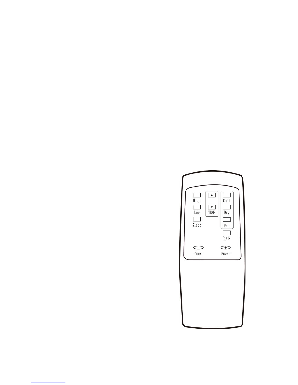
4. Operation instructions of the remote control
The operation instructions of the buttons of this simple remote control are as follows:
a) Power button: press this button to turn on/off the unit;
b) Timer button: upon shutdown, press this button to set timed start; upon start, press this
button to set timed shutdown.
c) High button: press this button to allow the unit to operate in the high fan speed state(except
in the dry and sleep modes);
d) Low button: press this button to allow this unit to operate in the low fan speed state;
e) Up button: press this button to increase the temperature and timing value;
f) Down button: press this button to decrease the temperature and timing value;
g) ˚C -˚F button: press this button to switch between the degree Celsius and
degree Fahrenheit;
h) Cool button: press this button to set this unit to operate in the cooling mode;
i) Fan button: press this button to set this unit to operate in the air supply mode;
j) Dry button: press this button to set this unit to operate in the dehumidifying mode;
k) Sleep mode: press this button to set this unit to operate in the sleep mode.

5. Multiple protection functions:
a) Anti-freeze protection function:
Upon cooling, when the compressors operates continuously for more than 10 minutes, if
the pipe temperature Tp is less than or equal to 2˚C continuously for 20 seconds, the
compressor will turn off, LED displays E4, the unit initiates the anti-frost protection function
and the buttons are inactive (except the OFF button). Once the pipe temperature rises to
exceed or equal 8˚C, 3 minutes the unit will return to normal operation after 3 minutes.
b) Full water protection function:
When the water in the water tray exceeds the alarm level, the unit will alarm automatically
and the full water indicator illuminates. Drain the water from the unit to prevent shutdown.
(For more information about the drain method, refer to the “Drain”).
c) Delay protection function of the compressor
This unit offers restart protection for the compressor. Except that the compressor may start
immediately when the unit is energized for the first time, there is 3-minute delay start
protection after the compressor is shut down.
REMOTE CONTROL
Buttons of the remote control operating
instructions as below:
1) High Press this button to select high fan speed
(except dehumidifying mode and sleep mode)
2) Low Press this button to select low fan speed.
3)Sleep Press this button to select sleep mode
4) Timer When turn off the unit, press this button
to set the time of turn on;when turn on the unit,
press this button to set the time of turn off
5) Up Press Up or Down button to set temperature
or adjust the time in Timer mode.
6)Down Press Up or Down button to set
temperature or adjust the time in Timer mode.
7) Cool Press this button to choose Cool mode.
8) Dry Press this button to choose Dry mode
9) Fan Press this button to choose Fan mode.
10) Press this button to change between
Celsius to Fahrenheit.
11) Power Press this button to turn the unit on/off.

WATER DRAINAGE
1. Manual drain: (as shown in Figure 10)
a) Once the unit shuts down upon full water, turn off the power of the unit and then
unplug the power plug.
Note: move the unit carefully to avoid spillage of water in the water tray at the bottom
of the unit.
b) Position a collection vessel below the water outlet at the back of the unit.
c) Screw off the drain cap, unplug the water plug and water will flow into the vessel
that holds water automatically.
Do not misplace the water plug and drain cap. Tilt the unit slightly backward when
draining. Once the water is fully drained, insert the water plug and screw on the water cap
tightly. Turn on the unit only after the water plug and drain cap are installed.
2. Continuous drain:
a) Screw off the water cap in the direction shown by the arrow and unplug the water
plug; (Figure 11)
b) Insert a OD 13mm PVC drain hose 8mm-10mm into the water outlet; (Figure 12)
c) Connect the drain hose to a water drain.
Place the drain hose in a place at a height below the water outlet and keep the
drain hose free from kinks. When continuous drain is used, store the drain cap and water
plug safely.
Figure 10
Water outlet
Water plug
Drain cap
Figure 11 Figure 12
Drain cap
Water outlet
Water plug
Drain hose
Note
Note

Figure 13 Figure 14
Gripping
position
Gripping
position
Gripping
position
Gripping
position
MAINTENANCE AND SERVICING
1) Prior to maintenance and servicing of the unit, turn off the power and unplug the plug.
a) Surface cleaning
Clean the surface of the unit with a clean damp soft cloth. Do not use chemical solvents
such as alcohol and petrol; as they may damage the air-conditioner
b) Cleaning of the filter frame and filter mesh
Clean the filter mesh every two weeks. If the filter frame and filter mesh are clogged with
dust or debris the function of the air-conditioner may be impaired.
2) Cleaning of the filter frame and filter mesh
a) Hold the filters removal tabs and remove by gently pulling in the direction shown by the
arrow (as shown in Figure 13 and 14.).
Note: When taking out the filter frame or filter mesh, the force shall be applied evenly to avoid
twisting or damage of the filter frame or filter mesh. Be sure to take out the filter frame first
and then take out the filter mesh.
b) Clean the filters in warm water (about 40˚C) add a neutral cleaner and then dry
(as shown in Figure 15).
3) Installation of the filter frame and filter mesh
Install the filter mesh first and then install
the filter frame.To install the evaporator filter mesh
and condenser filter mesh, point the back end of
the filter mesh toward the opening and then
push the filter mesh evenly and gently
into position.
a) To remove do the above in reverse.
b) The filter mesh must be installed into place;
otherwise, the filter frame may not be
installed correctly.
c) Install the filter mesh gently so as not
to damage it.
Figure 15
Note
Note

Remote
control
Remote control
storage area
Figure 16
HANDLING OF THE UNIT
Handling and moving of the unit
To handle or move the unit, hold the top of the
air outlet of the front shell with one hand and the
handle position at the top of the back shell with
another hand, ensure the unit remains in the
upright position. (As shown in Figure 17).
a) Do not handle the unit using the
horizontal louvre.
b) Keep upright when moving.
c) Drain before moving.
Air outlet
Handle position
Figure 17
Note

TROUBLESHOOTING
Never repair or remove parts of the air-conditioner yourself. Unauthorised repair will invalidate any
warranty and may cause harm to personnel injury or damage. If you encounter any of the problems
listed in the table below or the recommended remedy does not work, contact the sales outlet
where you purchased the unit is recommended.
Problem/fault
The air-conditioner
does not work
Bad cooling or
heating
effects
Large noise
The compressor
does not work
The remote control
does not work
Display E1
Display E2
Display E4
Full water indicator
illuminates
No power
Full water indicator illuminates?
Ambient temperature too low?
The room temperature is lower
than the set temperature in the
cooling mode.
There is direct sunlight
The doors and windows are
open, the room is crowded or
there are other heat sources in
the cooling mode
Filter mesh very dirty
Air inlet or air outlet clogged
Air-conditioner not put on a flat
surface
Initiation of overheat protection.
Too long a distance
The remote control does not
point toward the receiving head
of the remote control
The batteries have no electricity
Pipe temperature sensor failure
Room temperature sensor
failure
Anti-freeze protection
The water in the baseplate of
the unit reaches the full water
level
Connect the unit to a live socket and
turn it on.
Drain the water stored in the unit.
It is recommended that this unit be
operated at 10-35˚C.
Change the set temperature
Move unit into shaded area.
Close the door and window and add
new air-conditioners
Clean or replace the filter mesh
Remove the obstruction
Put the air-conditioner on a flat and
firm place (may reduce noise)
Wait 3 minutes until the temperature
decreases and then turn on the unit
Bring the remote control close to the
air-conditioner and ensure that the
remote control points toward the
receiving head of the remote control.
Replace the batteries
Refer to authorised repairer
Operation automatically restored when
when unit has defrosted
Restore the functions automatically
once defrozen.
Drain the water in the baseplate.
Cause Remedy
APPENDIX
Fuse parameters
Model: FSD or 50F
Voltage: 240V
Current: 3.15A
Schematic diagram of the air-conditioner
For specific technical parameters of the models, refer to the rating label on the product.
Disposal: Dispose of unit in accordance with local regulatory requirements .
Condenser
Compressor Evaporator
Capillary
This manual suits for next models
1
Table of contents
Other RHINO Air Conditioner manuals
Popular Air Conditioner manuals by other brands

Carrier
Carrier ASBFE600BA owner's manual

Mitsubishi Electric
Mitsubishi Electric MSC-GE20VB operating instructions

Whirlpool
Whirlpool BHAC1000XS0 Use & care guide

Panasonic
Panasonic CS-LZ9ZKA operating instructions

Daikin
Daikin RX15RMVJU installation instructions

Mitsubishi Electric
Mitsubishi Electric Mr.Slim PEA-M200 installation manual