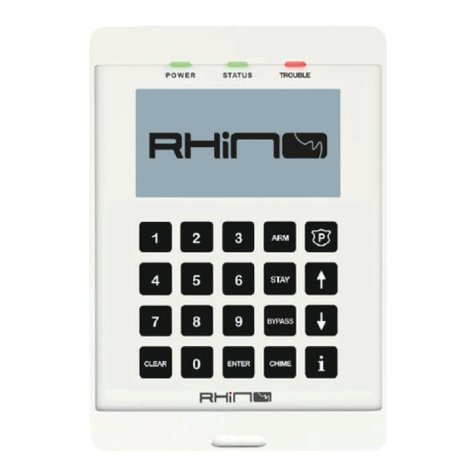
RHINO 832 User manual

RHINO 832
Zones - All OK
09 Dec 14:33
Ready
System - All OK

V1.4 13 October 2021

CONTENTS
General Overview ..................................................................................................................... 4
Rhino 832 Panel Overview .............................................................................................................................................................
Introduction .............................................................................................................................................................................................
Features ......................................................................................................................................................................................................
Remote keypads ...................................................................................................................................................................................
Wireless devices ....................................................................................................................................................................................
Upload/download software ...........................................................................................................................................................
Control panel layout .........................................................................................................................................................................
PCB Layout .............................................................................................................................................................................................
Connecting devices to the network........................................................................................................................................
Mounting the control panel.........................................................................................................................................................
Installing the expanders ...............................................................................................................................................................
Installing the keypads ....................................................................................................................................................................
Programming ............................................................................................................................
Entering the programming mode ..........................................................................................................................................
Navigating the programming menus ...................................................................................................................................
Zone options ........................................................................................................................................................................................
Rhino Upload/Download (UDL) .......................................................................................
Using the UDL .....................................................................................................................................................................................
Appendix A ...............................................................................................................................
Text Entry Mode ................................................................................................................................................................................
Hex Entry Mode ................................................................................................................................................................................
Warranty Information ..........................................................................................................
4
5
5
8
9
11
11
11
22
22
22
48
48
51
51
52
5
6
6
Installation Sequence ............................................................................................................
Getting Started ......................................................................................................................... 8
12
13
15
Other wiring .........................................................................................................................................................................................
Applying power to the control panel ..................................................................................................................................
Wired zones ......................................................................................................................................................................................
Wireless zones ................................................................................................................................................................................
20
21
23
Area options..........................................................................................................................................................................................
Hardware options..............................................................................................................................................................................
Keypad options ..................................................................................................................................................................................
Outputs ...................................................................................................................................................................................................
Communications ..............................................................................................................................................................................
Users .........................................................................................................................................................................................................
Programming wireless zones ................................................................................................................................................ 25
29
32
36
37
40
42
51
Zone Commissioning Process .......................................................................................... 44
7
Setting up the zones ....................................................................................................................................................................... 13
GENERAL OVERVIEW
Rhino 832 Panel Overview
Wireless
Remote
LCD Keypad
Rhino 832
Control Panel
4 Programmable
Outputs (1A)
8 Wired Zone
Inputs
LCD Keypad
4 Wire Bus
Wireless Devices
Indoor PIR Door
Contact
Wireless Gate Module
Third Party
PIR Interface
USB Port
Internet
FSK Gateway Alarm Receiving
Centre
PC for local
Upload/Download PC and modem for
Remote
Upload/Download
Smart Phone Apps
Up to 32 Wireless
Zones
RHINO 832
Zones - All OK
09 Dec 14:33
123ARM P
456
789
CLEAR 0CHIME
ENTER
STAY
BYPASS
RHINO 832
123ARM P
456
789
CLEAR 0CHIME
ENTER
STAY
BYPASS
4 Rhino 832 Installation Manual |
Ready
System - All OK
Zones - All OK
09 Dec 14:33
Ready
System - All OK
8-zone wired
expander
(plug-in)
8-zone expander
fitted inside the
control panel
16-zone Wired
Expander
Up to 4 keypads

The Rhino 832 is a wired and wireless alarm panel
The Rhino 832 panel is equipped with an onboard GSM modem which sends alarms to the
control room
The Rhino 832 panel works with the MiRhino mobile application which allows the user to
remotely control and monitor their alarm system
The Rhino 832 panel has been designed with ease-of-use, ease-of-installation and ease-of-
programming in mind
1. Introduction
2. Features of the Rhino 832 Panel
8 onboard zones, expandable to 16 onboard zones with a Rhino 832 8-zone plug-in
expander
Further expandable to 32 wired zones with the use of a bus-wired expander that adds an
additional 16 zones
Or up to 32 fully supervised wireless zones
The system may have a combination of wired and wireless zones totalling 32 zones
4 partitions
3 stay profiles per partition
Up to 4 Graphic LCD keypads
Zones and Partitions
20 users and 20 remote controls (one per user)
Options to set user codes as master, standard, duress or arm-only
MiRhino app functionality
Users
Menu-driven programming for the installer for easy programming without the use of
location numbers
Local or remote upload/download
Local or over-the-air panel firmware upgrades
Advanced system diagnostics
Plug-in wireless transceiver
4 programmable onboard outputs
Up to 32 wireless outputs
1000 event log with date and time
Battery self-test
Low battery monitoring
System Options
The Rhino 832 panel will accept up to a maximum of 4 remote Graphic LCD keypads. All remote
keypads require a 4-wire connection to the control panel using standard alarm cable.
3. Remote Keypads
The Graphic LCD keypad features a 128 x 64 pixel display on which all zone, area and system
statuses are displayed. A set of dedicated system status LEDs for Power, Status and Trouble are
also provided. Other features include:
Rhino 832 Installation Manual 5 |

4-wire bus connection using standard alarm cable
Internal sounder
Backlit keyboard with adjustable brightness
Full system programming and diagnostics
Indoor PIR
An indoor 12 metre Passive Infrared (PIR) detector.
Door Contact
A magnetic door contact sensor with an additional zone input for monitoring other
normally closed detectors.
Bidirectional Gate Module
A small module with a single zone input and one controllable output.
Raptor Remote Control 6 Button
A remote control for remotely arming, disarming and switching outputs on and off.
Third Party PIR Interface
A module that interfaces with third party PIRs e.g. Takex.
Raptor Repeater
A module used to extend the range of wireless devices.
The following wireless devices are available:
Simple intuitive user interface
Local or remote programming via the FSK Gateway
System remote control
Advanced system diagnostics
Rhino UDL is a Windows® based software package that can be used to remotely or locally
program and diagnose the Rhino range of security systems. Features include:
4. Wireless Devices
5. Upload/download Software
6 Rhino 832 Installation Manual |

INSTALLATION SEQUENCE
Read this section before attempting to install the alarm system. Once you have an overall
understanding of the installation sequence, carefully work through each step.
1: Design the Layout
Make a sketch of the premises to get an idea of where all alarm detection devices, keypads and
other modules are to be located.
2: Mount the Panel
The control panel should be mounted in a dry area, out of sight, close to an AC power source.
3: Install the Keypads
Mount the remote keypads at locations that are easily accessible during entry and exit from the
protected area. Connect the remote keypads to the control panel.
4: Set up the Zones
Install all detection devices (including wireless) and connect the wired devices to the control
panel or expander. Note that the wireless devices can only be configured during programming
5: Other Wiring
Complete all other wiring including bells or strobe lights.
6: Apply Power to the Control Panel
Once steps 1 to 5 are completed, apply power to the control panel. First, connect the red battery
lead to the positive terminal and then the black lead to the negative terminal. Then, connect the
AC.
7: Program the System
The panel can be programmed using the keypad or the software supplied on the FSK DVD which
can be done via USB connection or remotely via the FSK Gateway.
8: Test the System
Test the system thoroughly and perform the zone commissioning procedure on page 40 for
wireless zones, to ensure all features and functions are operating as required.
Rhino 832 Installation Manual 7 |

GETTING STARTED
Control Panel Layout
8 Rhino 832 Installation Manual |
AC AC R B G Y Z1
KEYPAD/BUS C CZ2
12V
Z3 Z4Z5 Z6C
12V
12V
Z7 C Z8
OUT1
SRN
12V
OUT
OUT2
STB
OUT3
12V
OUT
OUT4
USB
P1 PROG
R4
R5
R2
TZ4
TZ1
Z8Z7Z6Z5Z4Z3Z2Z1
Q1
F1
12V
BUS
TZ6
D4
D7 R45
R44
D9 R9
R16
R11
R18
R83
R87
R84
R89
R93
R94
R95
R97 R105
R109
R111 R112
R115
F4
R86
12V
ZONE
LED12
R80
R79
R81
R82
C38
Q3 Q5 Q7 Q8
R36
R34
R30
R32 R35
F3
R24
R25
R31
U10
R75
R76
R77
R78
R91R85
Q16
R10
Z10Z9Z8Z7Z6Z5Z4Z3
TP4
R13
R21C25
Q2
U4
D10 C39 C40
R118
C42 C44C43 C45 C48 C49
C1
U3
U1
WIRELESS
P2
C7
C2
C10
TP2
TP1
C16
D3
C15
U5
R92Q17
Z11
R99
R101
R100
U11
C41
C47
U12
C46
Z1
R15
R23
C19
Z2
C18
R37
C23
R42
R49
Q10
P3
R48
BATT
Q9R46
C22 U6
R38
D5
X
777
D8
L1
C21
R27
C14 R28
R26
C24
Q6 R33
1
GSM2
Q13 R60 Q11
R51
X1
C11
R8
C8
RUN
JTAG1
R7
R6
TAMPER
J1
TB
LED3
U2C9
R1
C6
C4C3
C32
R57
SC3
U7
R59 R58 R56
SC1
C31
R50
SC4
R17
R19
R117
R71
R72
R73
R74
C37 U9
R67
R68
R69
R70
SIM
CARD
R52 Q12 GSM
LED2
C30
GSM ANT1
C29
GSM
R55
R53
R54
SIM7100C
P/N: S2-10000
SN: D000000000000
IMEI:
860000000000
SIM
Com
P4
R41
R65
R39
Q15
R63
Q4
C20
D2
R62
D1
F2
P5
C35
Q14
R22
R102
R103
R106
R64
U8
TP3
C33
C26
C27
C28
C34
C36
R66
R12
EXP
T0263
ALU
G
ALU
G
ELECTRONICS SA (PTY) LTD
AP Rhino832 PCB
ISSUE C
1
2
3

1. Main Printed Circuit Board (PCB)
The main PCB that provides the terminals connection to remote keypads and detection devices.
See below PCB Layout for full details.
2. Standby Battery
The system housing will accept a 12V 7Ah battery to provide continued operation in the event of
an AC mains failure. Connect the red battery lead to the positive terminal of the battery and then
connect the black battery lead to the negative terminal.
3. GSM Antenna
Screw-in GSM antenna.
PCB Layout
1. AC Terminals
The three wires from the transformer are connected to these terminals to supply power to the
system.
AC AC R B G Y Z1
KEYPAD/BUS C CZ2
12V
Z3 Z4Z5 Z6C
12V
12V
Z7 C Z8
OUT1
SRN
12V
OUT
OUT2
STB
OUT3
12V
OUT
OUT4
USB
P1 PROG
R4
R5
R2
TZ4
TZ1
Z8Z7Z6Z5Z4Z3Z2Z1
Q1
F1
12V
BUS
TZ6
D4
D7 R45
R44
D9 R9
R16
R11
R18
R83
R87
R84
R89
R93
R94
R95
R97 R105
R109
R111 R112
R115
F4
R86
12V
ZONE
LED12
R80
R79
R81
R82
C38
Q3 Q5 Q7 Q8
R36
R34
R30
R32 R35
F3
R24
R25
R31
U10
R75
R76
R77
R78
R91R85
Q16
R10
Z10Z9Z8Z7Z6Z5Z4Z3
TP4
R13
R21C25
Q2
U4
D10 C39 C40
R118
C42 C44C43 C45 C48 C49
C1
U3
U1
WIRELESS
P2
C7
C2
C10
TP2
TP1
C16
D3
C15
U5
R92Q17
Z11
R99
R101
R100
U11
C41
C47
U12
C46
Z1
R15
R23
C19
Z2
C18
R37
C23
R42
R49
Q10
P3
R48
BATT
Q9R46
C22 U6
R38
D5
X
777
D8
L1
C21
R27
C14 R28
R26
C24
Q6 R33
1
GSM2
Q13 R60 Q11
R51
X1
C11
R8
C8
RUN
JTAG1
R7
R6
TAMPER
J1
TB
LED3
U2C9
R1
C6
C4C3
C32
R57
SC3
U7
R59 R58 R56
SC1
C31
R50
SC4
R17
R19
R117
R71
R72
R73
R74
C37 U9
R67
R68
R69
R70
SIM
CARD
R52 Q12 GSM
LED2
C30
GSM ANT1
C29
GSM
R55
R53
R54
SIM7100C
P/N:
S2-10000
SN:
D000000000000
IMEI:
860000000000
SIM
Com
P4
R41
R65
R39
Q15
R63
Q4
C20
D2
R62
D1
F2
P5
C35
Q14
R22
R102
R103
R106
R64
U8
TP3
C33
C26
C27
C28
C34
C36
R66
R12
EXP
T0263
ALU
G
ALU
G
ELECTRONICS SA (PTY) LTD
AP Rhino832 PCB
ISSUE C
1 2 3
4
56
7
8
91011
11
Rhino 832 Installation Manual 9 |
12

2. Bus Terminals
The bus terminals provide connections to the remote keypads. The R (Red) and B (Black) terminals
provide power whilst the G (Green) and Y (Yellow) terminals are the data signals.
3. Zone Inputs 1 to 8
Detection devices such as PIR sensors, vibration sensors and door contacts are connected to the
zone input terminals. There are several ways in which to wire a detection device (see page 12).
Each zone is fully programmable. See page 22 for information on programming zones.
4. Auxiliary 12V
These terminals provide auxiliary power for the external sounder and detection devices that
require 12V power, e.g., movement sensors. The auxiliary output is protected by an auto resetting
fuse (PTC) rated at 1.1 Amp.
5. Panel Outputs 1 to 4
These are fully programmable high current (1 Amp), open drain (negative switched) supervised
outputs. Panel outputs 1 and 2 default to bell and strobe operation, but can be programmed for
other functions if required. See page 33 for programming details.
6. USB Connection
A micro USB port is used for local connection to Rhino UDL and/or firmware updating software
from a Windows PC.
7. Run LED
Flashes when the panel is powered and operational.
8. Lid Tamper Connector
The lid tamper switch should be connected here to provide protection for when the enclosure
cover is opened.
9. 7 Segment Display
The 7 Segment Display indicates the GSM status of the panel.
10. GSM Antenna Connector
This connector provides a screw in connection for the GSM modem antenna.
11. Battery Connections
A 12V rechargeable battery must be connected to these two terminals in order to provide
continuous system operation in the event of mains failure. The battery output is protected by an
auto resetting fuse (PTC) rated at 1.6 Amp.
12. Expander Plug Connector
The Rhino 832 8-zone expander is connected here.
10 Rhino 832 Installation Manual |

Connecting devices to the network
Before connecting devices to the control panel bus, isolate ALL power from the control panel (AC
Mains & Battery). Do not continue if there is still power present on the control panel.
Note: Connecting devices with power still present on the control panel may damage the device
or control panel and invalidate any warranty.
Mounting the control panel
Mount the control panel on a flat, plumb wall using at least three appropriate screws. The rear
casing has been designed with several key-hole slots so that mounting is possible without
removing the Printed Circuit Board (PCB). It is essential to ensure that none of the fixing slots or
cable entries are accessible after fixing.
Installing the expanders
8-zone wired expander
This expander is plugged into the connector of the Rhino 832 PCB as shown on the PCB Layout on
page 9.
16-zone wired expander
The external 16-zone expander connects to the same network terminals as the keypads. These are
located at the bottom left hand corner of the control panel.
Note: The 16-zone expander operates with its own transformer and standby battery.
Network Connections
The network is made up of four terminals incorporating power and data. To ensure correct
operation, all four terminals on the device must be connected to the corresponding terminals on
the control panel, or previous device.
Rhino 832 Installation Manual 11 |
Up to 100 metres
16-zone Expander
R B G Y
Control Panel
YEL
GRN
BLK
RED
Network

Installing the keypads
Remote keypads are all connected to the bus terminals located at the bottom left hand corner of
the control panel and may be connected serially (daisy chain), in parallel (star) or any combination
of the two.
Cable Type & Distances
For improved immunity to electrical noise, the use of screened 4 core cable is recommended. The
screen should be twisted together and wired into the (–) terminal at the control panel only.
The maximum recommended distance for devices when using standard 7/0.2 alarm cable is:
100m for each branch when using the star (parallel) configuration.
When using a daisy chain (series) configuration, the maximum distance will depend on the
number of devices connected on the chain. The more devices that are connected, the shorter the
distance to the last device (this is due to voltage drop in the cable).
Whichever method of wiring configuration is used, ensure that the voltage between the '+' and '–'
terminals at each device is no lower than 10.0V when the system is running on the standby
battery.
Overcoming Voltage Drop
There are several ways to overcome voltage drop:
Installing a Power Supply
When a power supply is installed, the 0V connections on the power supply must be connected
through to 0V on the control panel and the +12V connection between the control panel and the
device must be disconnected (see figure on next page).
Up to 100 metres
Remote Keypad
1
Remote Keypad
2
Remote Keypad
3
Remote Keypad
4
R B G Y
R B G Y R B G YR B G Y
Control Panel
YEL
GRN
BLK
RED
Network
Use thicker lower resistance cable. Standard 7/0.2 alarm cable has a resistance of 8Ω per
100m.
Double up on the power connections – this will require using a 6 or 8-core cable rather than
a 4-core cable.
Install a power supply to power the device locally, remember to common the two negative
connections.
12 Rhino 832 Installation Manual |

*N.B. The maximum tested network distance is 100m.
Setting up the zones
There are several different wiring options and each zone can be wired with a different method.
Wired zones
All zones can be wired using one of the following wiring options. The zone must be programmed
to match the wiring used. See zone wiring method option on page 25.
Normally Closed (NC)
This wiring configuration should be used when connecting detection devices that only have a
normally closed alarm output. Connect the detector as shown in the figure below and ensure that
the zone is programmed for normally closed operation.
Up to 100 metres
Control Panel
YEL
GRN
BLK
RED
Network
Remote Keypad
Address = 1
Remote Keypad
Address = 2
Remote Keypad
Address = 3
Remote Keypad
Address = 3
R B G YR B G YR B G YR B G Y
Power Supply
Disconnect +12V
from control panel
Alarm
Detector
Zx Com Zy
Rhino 832 Installation Manual 13 |
Normally Open (NO)
This wiring configuration should be used when connecting detection devices that only have a
normally open alarm output. Connect the detector as shown below and ensure that the zone is
programmed for normally open operation. See page 25.

Single End of Line (EOL) - NC
This wiring configuration should be used when connecting detection devices that only have a
normally closed alarm output. Connect the detector as shown below and ensure that the zone is
programmed for single EOL – NC operation. See page 25.
Alarm
Detector
Zx Com Zy
Detector
Zx Com Zy
Alarm
Double End of Line (EOL)
This wiring configuration should be used when connecting detection devices that have a normally
closed alarm and tamper output. Connect the detector as shown below and ensure that the zone
is programmed for "Double EOL" operation. See page 25.
14 Rhino 832 Installation Manual |
3K3

Rhino 832 Installation Manual 15 |
Detector
Zx Com Zy
Tamper
2K2
4K7
Alarm
E.O.L
Wireless Zones
The Rhino 832 has a wireless transceiver that is plugged onto the main PCB. It allows support for
various wireless devices. The following wireless devices are compatible with the Rhino 832 panel.
RH-100 Wireless Door Contact
The RH-100 is a professional state-of-the-art wireless door contact sensor. It has two zones, one on
the magnetic (reed) switch and the other on the zone input terminals.
The RH-100 must be allocated to one of the available zones (1-32). When a zone has been
programmed as a wireless zone, it cannot function as a wired zone anymore (the wired input is
disabled). Refer to the door contact leaflet.
The figure below shows the layout of the RH-100 Wireless Door Contact:
BATTERY
CR2
6
5
4
2
3
1
1. Battery
Use a CR2 3V Li-ion battery. Observe the polarity.

2. Tamper switch
The tamper switch is used to detect the removal of the lid. It is also used for learning the device
into the alarm panel.
3. Activity LED
The LED is on when the device is sending a signal to the alarm panel.
4. Zone input terminals
The wireless door contact has two detector inputs. The first is the reed switch which is activated
by the magnet. The second requires a voltage-free normally closed contact to be wired into the
terminals. Both inputs report back to the same zone on the control panel. If the zone is not used,
it should be shorted with a link.
5. Magnetic reed switch
The magnetic reed switch detects the presence of the magnet fitted to the door. There is a
marking on the door contact which indicates where the magnet should be centred. The magnet
should be mounted within 15mm of the door contact (when the door is closed).
Note: The magnetic reed switch is always in operation. If you only require the use of the zone
input terminals, the magnet must be held close to the reed switch at all times.
6. Antenna
The antenna is used for transmitting the wireless signal.
Note: Avoid mounting the door contact on or near a metal frame as this will negatively affect
communications with the alarm panel.
RH-101 Wireless 3rd Party PIR Interface
The RH-101 is a third party wireless interface. When wired to a third party PIR device, it will
provide wireless connectivity from the device to the Rhino 832 alarm panel. The RH-101 has a
normally closed alarm input as well as a normally closed tamper input. The tamper contact is also
wired in series with the internal tamper switch.
The RH-101 must be allocated to one of the wireless zones (1-32). When a zone has been
programmed as a wireless zone, it cannot function as a wired zone anymore (the wired input is
disabled). Refer to the in-box leaflet for more information.
16 Rhino 832 Installation Manual |

The figure below shows the layout of the RH-101 Wireless 3rd Party PIR Interface:
1. Battery
Use a CR2 3V Li-ion battery. Observe the polarity.
2. Tamper switch
The internal tamper switch is used to detect the removal of the lid. It is also used for learning the
device into the panel. The internal tamper switch is connected in series with the tamper input (5).
3. Activity LED
The LED is on when the device is sending a signal to the alarm panel.
4. Alarm input terminal
Connect the alarm output of the third party detection device to the alarm input of the RH-101.
5. Tamper input terminal
The tamper input should be wired in series with the alarm input.
6. Antenna
The antenna is used for transmitting the wireless signal.
Note: Avoid mounting the unit on or near a metal object as this will negatively affect
communications with the alarm panel.
RH-200 Wireless Indoor Passive
The RH-200 indoor PIR has a built-in wireless transceiver for direct communication to the Rhino
832 panel. The PIR should be allocated to one of the available zones (1-32). When a zone has been
programmed as a wireless zone, it cannot function as a wired zone anymore (the wired input is
disabled). Refer to the in-box leaflet for more information.
Rhino 832 Installation Manual 17 |
6
5
4
2
1
3

The figure below shows the layout of the RH-200 Wireless Indoor Passive:
1. Battery
Use a CR123A 3V Li-ion battery. Observe the polarity (the positive terminal is marked).
2. Tamper switch
The internal tamper switch detects that the lid has been opened. It is also used for learning the
device into the panel.
3. Activity LED
The LED switches on when movement is detected.
4. Sensitivity Jumper
If the jumper is inserted, the sensitivity is normal. If it is removed, the sensitivity is high.
5. LED Jumper
If the jumper is inserted, the LED is enabled. If it is removed, the LED is disabled.
Raptor Bidirectional Gate Module
The Raptor gate module is a bi-directional wireless module with one input and one output. The
input can be used as a wireless zone to monitor and provide remote feedback. The output can be
used to remotely control equipment such as a gate motor.
The Raptor gate module must be allocated to one of the available zones (1-32). When a zone has
been programmed as a wireless zone, it cannot function as a wired zone anymore (the wired
input is disabled). Refer to the in-box leaflet for more information.
18 Rhino 832 Installation Manual |
5
4
3
2
1

The figure below shows the layout of the Raptor Gate Module:
1. Power supply terminals - 12-24V DC
2. Relay output - common, normally closed and normally open terminals
3. Input (positive and negative triggers)
4. Ground terminal for inputs
5. Learn button
6. Relay on/off status LED
7. Wireless activity LED
Raptor Wireless Remote Control
The Raptor remote control is a bi-directional remote control which is used to remotely control the
alarm panel. It has an arm, stay arm, disarm and panic button. It also has two programmable
buttons which can be used to remotely control outputs on modules that are connected to the
panel. Refer to the Raptor Remote Control product manual for more information.
1. Panic alarm
This button activates the panic alarm.
2. Away arm
This button away arms the areas allocated to the user.
3. Disarm
This button disarms the areas allocated to the user.
Rhino 832 Installation Manual 19 |
1
67 5
2 3 4
7
6
4
2
5
3
1

4. Stay arm
This button stay arms, in Stay Arm 1 mode, the areas allocated to the user.
5 & 6 Spare Buttons
These buttons can be programmed to remotely control an output or Raptor Gate Module to open
a gate.
7 Activity LED
The activity LED illuminates when the remote is transmitting or receiving a wireless signal.
Other wiring
External Sounder/Strobe Connections
The following connections are available for connection to an external sounder/strobe unit:
OUT1/SRN
Panel output 1 is pre-configured for bell/siren (SRN) operation (active low). Connect the negative
of the bell/siren to this output if required.
+12V OUT
This is a +12V output to supply power to devices connected to the outputs. The +12V output is
protected by an auto resetting fuse (PTC) rated at 1.1A.
OUT2/STB
Panel output 2 is pre-configured for strobe operation (active low). Connect negative of the strobe
to this output if required.
Panel Outputs 1 - 4
The control panel has four programmable outputs, which can be used to drive auxiliary devices
such as LEDs, sounders or relays etc. See page 33 for details on programming outputs. Each panel
output is rated at 1 Amp and switches to 0V when active. The figure below shows some wiring
examples:
20 Rhino 832 Installation Manual |
Control PanelControl Panel
12V Strobe
12V Siren
0V 12V 1 2
Control Panel
LED
12V OP
LED Indicator
1K
cathode
anode
Table of contents
Other RHINO Security System manuals

RHINO
RHINO Watchguard Digital V2 User manual

RHINO
RHINO RA97 User manual

RHINO
RHINO RCA User manual

RHINO
RHINO RCA-2 User manual

RHINO
RHINO ADVANCED PANIC PACK User manual

RHINO
RHINO Watchguard Digital V2 User manual

RHINO
RHINO 232 User manual

RHINO
RHINO PelcoD 2400bps on RS485 User manual

RHINO
RHINO RA96 User manual
Popular Security System manuals by other brands

Whelen Engineering Company
Whelen Engineering Company SS361 installation guide

Whelen Engineering Company
Whelen Engineering Company WS2100 Series installation guide

SOUJAMAO
SOUJAMAO B07VCNDQ7Z user manual

Bentel Security
Bentel Security Base-2 Installer and user guide

Pyronix
Pyronix PCX 46 Engineer Reference Manual

Aico
Aico Ei3030 instruction manual